EP1519261A2 - Méthode, appareil, système et programme pour créer, enregistrer et lire une image de système sous forme de fichier, un support stockant le programme et un support stockant l'image de système sous forme de fichier - Google Patents
Méthode, appareil, système et programme pour créer, enregistrer et lire une image de système sous forme de fichier, un support stockant le programme et un support stockant l'image de système sous forme de fichier Download PDFInfo
- Publication number
- EP1519261A2 EP1519261A2 EP04255892A EP04255892A EP1519261A2 EP 1519261 A2 EP1519261 A2 EP 1519261A2 EP 04255892 A EP04255892 A EP 04255892A EP 04255892 A EP04255892 A EP 04255892A EP 1519261 A2 EP1519261 A2 EP 1519261A2
- Authority
- EP
- European Patent Office
- Prior art keywords
- file
- user data
- optical disc
- directory
- session
- Prior art date
- Legal status (The legal status is an assumption and is not a legal conclusion. Google has not performed a legal analysis and makes no representation as to the accuracy of the status listed.)
- Withdrawn
Links
Images


Classifications
-
- G—PHYSICS
- G06—COMPUTING OR CALCULATING; COUNTING
- G06F—ELECTRIC DIGITAL DATA PROCESSING
- G06F3/00—Input arrangements for transferring data to be processed into a form capable of being handled by the computer; Output arrangements for transferring data from processing unit to output unit, e.g. interface arrangements
- G06F3/06—Digital input from, or digital output to, record carriers, e.g. RAID, emulated record carriers or networked record carriers
- G06F3/0601—Interfaces specially adapted for storage systems
- G06F3/0602—Interfaces specially adapted for storage systems specifically adapted to achieve a particular effect
- G06F3/0604—Improving or facilitating administration, e.g. storage management
- G06F3/0607—Improving or facilitating administration, e.g. storage management by facilitating the process of upgrading existing storage systems, e.g. for improving compatibility between host and storage device
-
- G—PHYSICS
- G11—INFORMATION STORAGE
- G11B—INFORMATION STORAGE BASED ON RELATIVE MOVEMENT BETWEEN RECORD CARRIER AND TRANSDUCER
- G11B20/00—Signal processing not specific to the method of recording or reproducing; Circuits therefor
- G11B20/10—Digital recording or reproducing
- G11B20/12—Formatting, e.g. arrangement of data block or words on the record carriers
-
- G—PHYSICS
- G06—COMPUTING OR CALCULATING; COUNTING
- G06F—ELECTRIC DIGITAL DATA PROCESSING
- G06F3/00—Input arrangements for transferring data to be processed into a form capable of being handled by the computer; Output arrangements for transferring data from processing unit to output unit, e.g. interface arrangements
- G06F3/06—Digital input from, or digital output to, record carriers, e.g. RAID, emulated record carriers or networked record carriers
- G06F3/0601—Interfaces specially adapted for storage systems
- G06F3/0602—Interfaces specially adapted for storage systems specifically adapted to achieve a particular effect
- G06F3/0608—Saving storage space on storage systems
-
- G—PHYSICS
- G06—COMPUTING OR CALCULATING; COUNTING
- G06F—ELECTRIC DIGITAL DATA PROCESSING
- G06F3/00—Input arrangements for transferring data to be processed into a form capable of being handled by the computer; Output arrangements for transferring data from processing unit to output unit, e.g. interface arrangements
- G06F3/06—Digital input from, or digital output to, record carriers, e.g. RAID, emulated record carriers or networked record carriers
- G06F3/0601—Interfaces specially adapted for storage systems
- G06F3/0628—Interfaces specially adapted for storage systems making use of a particular technique
- G06F3/0638—Organizing or formatting or addressing of data
- G06F3/0643—Management of files
-
- G—PHYSICS
- G06—COMPUTING OR CALCULATING; COUNTING
- G06F—ELECTRIC DIGITAL DATA PROCESSING
- G06F3/00—Input arrangements for transferring data to be processed into a form capable of being handled by the computer; Output arrangements for transferring data from processing unit to output unit, e.g. interface arrangements
- G06F3/06—Digital input from, or digital output to, record carriers, e.g. RAID, emulated record carriers or networked record carriers
- G06F3/0601—Interfaces specially adapted for storage systems
- G06F3/0628—Interfaces specially adapted for storage systems making use of a particular technique
- G06F3/0638—Organizing or formatting or addressing of data
- G06F3/0644—Management of space entities, e.g. partitions, extents, pools
-
- G—PHYSICS
- G06—COMPUTING OR CALCULATING; COUNTING
- G06F—ELECTRIC DIGITAL DATA PROCESSING
- G06F3/00—Input arrangements for transferring data to be processed into a form capable of being handled by the computer; Output arrangements for transferring data from processing unit to output unit, e.g. interface arrangements
- G06F3/06—Digital input from, or digital output to, record carriers, e.g. RAID, emulated record carriers or networked record carriers
- G06F3/0601—Interfaces specially adapted for storage systems
- G06F3/0668—Interfaces specially adapted for storage systems adopting a particular infrastructure
- G06F3/0671—In-line storage system
- G06F3/0673—Single storage device
- G06F3/0674—Disk device
- G06F3/0677—Optical disk device, e.g. CD-ROM, DVD
-
- G—PHYSICS
- G11—INFORMATION STORAGE
- G11B—INFORMATION STORAGE BASED ON RELATIVE MOVEMENT BETWEEN RECORD CARRIER AND TRANSDUCER
- G11B20/00—Signal processing not specific to the method of recording or reproducing; Circuits therefor
- G11B20/10—Digital recording or reproducing
- G11B20/12—Formatting, e.g. arrangement of data block or words on the record carriers
- G11B20/1262—Formatting, e.g. arrangement of data block or words on the record carriers with more than one format/standard, e.g. conversion from CD-audio format to R-DAT format
-
- G—PHYSICS
- G11—INFORMATION STORAGE
- G11B—INFORMATION STORAGE BASED ON RELATIVE MOVEMENT BETWEEN RECORD CARRIER AND TRANSDUCER
- G11B27/00—Editing; Indexing; Addressing; Timing or synchronising; Monitoring; Measuring tape travel
- G11B27/02—Editing, e.g. varying the order of information signals recorded on, or reproduced from, record carriers
- G11B27/031—Electronic editing of digitised analogue information signals, e.g. audio or video signals
- G11B27/034—Electronic editing of digitised analogue information signals, e.g. audio or video signals on discs
-
- G—PHYSICS
- G11—INFORMATION STORAGE
- G11B—INFORMATION STORAGE BASED ON RELATIVE MOVEMENT BETWEEN RECORD CARRIER AND TRANSDUCER
- G11B27/00—Editing; Indexing; Addressing; Timing or synchronising; Monitoring; Measuring tape travel
- G11B27/10—Indexing; Addressing; Timing or synchronising; Measuring tape travel
- G11B27/102—Programmed access in sequence to addressed parts of tracks of operating record carriers
- G11B27/105—Programmed access in sequence to addressed parts of tracks of operating record carriers of operating discs
-
- G—PHYSICS
- G11—INFORMATION STORAGE
- G11B—INFORMATION STORAGE BASED ON RELATIVE MOVEMENT BETWEEN RECORD CARRIER AND TRANSDUCER
- G11B27/00—Editing; Indexing; Addressing; Timing or synchronising; Monitoring; Measuring tape travel
- G11B27/10—Indexing; Addressing; Timing or synchronising; Measuring tape travel
- G11B27/19—Indexing; Addressing; Timing or synchronising; Measuring tape travel by using information detectable on the record carrier
- G11B27/28—Indexing; Addressing; Timing or synchronising; Measuring tape travel by using information detectable on the record carrier by using information signals recorded by the same method as the main recording
- G11B27/32—Indexing; Addressing; Timing or synchronising; Measuring tape travel by using information detectable on the record carrier by using information signals recorded by the same method as the main recording on separate auxiliary tracks of the same or an auxiliary record carrier
- G11B27/327—Table of contents
- G11B27/329—Table of contents on a disc [VTOC]
-
- G—PHYSICS
- G11—INFORMATION STORAGE
- G11B—INFORMATION STORAGE BASED ON RELATIVE MOVEMENT BETWEEN RECORD CARRIER AND TRANSDUCER
- G11B2220/00—Record carriers by type
- G11B2220/20—Disc-shaped record carriers
-
- G—PHYSICS
- G11—INFORMATION STORAGE
- G11B—INFORMATION STORAGE BASED ON RELATIVE MOVEMENT BETWEEN RECORD CARRIER AND TRANSDUCER
- G11B2220/00—Record carriers by type
- G11B2220/20—Disc-shaped record carriers
- G11B2220/21—Disc-shaped record carriers characterised in that the disc is of read-only, rewritable, or recordable type
- G11B2220/213—Read-only discs
-
- G—PHYSICS
- G11—INFORMATION STORAGE
- G11B—INFORMATION STORAGE BASED ON RELATIVE MOVEMENT BETWEEN RECORD CARRIER AND TRANSDUCER
- G11B2220/00—Record carriers by type
- G11B2220/20—Disc-shaped record carriers
- G11B2220/25—Disc-shaped record carriers characterised in that the disc is based on a specific recording technology
- G11B2220/2537—Optical discs
- G11B2220/2545—CDs
Definitions
- the present invention relates to a technique of creating, recording and reading a system file image, and more particularly to a method, apparatus, system, and computer program and medium for creating, recording, and reading a system file image for an optical disc, and a medium storing the system file image.
- Optical discs such as CDs and DVDs, are widely used for information delivery. To increase compatibility among a variety of platforms and operating systems, various standards are introduced to the logical formats of the optical discs.
- the ISO 9660 standard (hereinafter, referred to as the ISO standard) is a logical format designed originally for CD-ROMs, which can be utilized by a variety of operating systems, including MS-DOS, Windows, Macintosh, and UNIX.
- the ISO standard has a strong DOS influence that may lead to some limitations, such as the limitations in character set, file name length, and/or directory tree depth, for example.
- some extensions to the ISO 9660 standard are introduced, such as Joliet and Rock Ridge.
- UDF universal disc format
- FIGS. 1A and 1B illustrate an exemplary structure of an optical disc volume created in compliance with the Joliet standard, using a conventional technique.
- the Joliet standard utilizes a SVD (supplementary volume descriptor) to support a Unicode character set.
- SVD supplementary volume descriptor
- the disc volume includes a system area and a data area.
- the system area which includes logical sectors 0 through 15, is reserved for system use.
- the data area which includes the remaining logical sectors, stores actual user data and is organized into a plurality of logical blocks assigned with unique logical block numbers (LBA).
- LBA unique logical block numbers
- the data area additionally includes a group of descriptors, including volume descriptors, path tables, and file/directory descriptors.
- the volume descriptor includes a PVD (primary volume descriptor) and the SVD, and is terminated by a volume descriptor set terminator (VDT).
- the volume descriptor may additionally include a volume partition descriptor and a boot descriptor.
- the path tables include a path table defined in the ISO standard ("ISO path table”) and a path table defined in the Joliet standard (“Joliet path table”).
- the file/directory descriptors include a root directory descriptor defined in the ISO standard ("ISO root directory”), a subdirectory descriptor defined in the ISO standard (“ISO subdirectory”), a root directory descriptor defined in the Joliet standard (“Joliet root directory”), and a subdirectory descriptor defined in the Joliet standard (“Joliet subdirectory”).
- the group of descriptors stores various kinds of information regarding the user data stored in the disc volume, including information regarding its size and location in the directory hierarchy, for example.
- FIG. 2 illustrates an exemplary directory hierarchy, in which the user data is stored in a subdirectory named "DIR 2" under a root directory.
- the group of descriptors shown in any one of FIGS. 1A and 1B stores information in a manner described referring to FIG. 1C.
- the PVD starts at the LBA Of 16.
- the ISO root directory starts at the LBA of J1.
- the Joliet root directory starts at the LBA of J2.
- the ISO root directory starts at the LBA of J3.
- the ISO subdirectory starts at the LBA of J4.
- the Joliet root directory starts at the LBA of J6.
- the Joliet subdirectory starts at the LBA of J7.
- the user data is stored at the LBA of J9.
- the PVD stores the number ("J1") assigned to the LBA starting the ISO path table, as a link to the ISO path table.
- the PVD further stores the number (“J3") assigned to the LBA starting the ISO root directory, as a link to the ISO root directory.
- the SVD stores the number ("J2") assigned to the LBA starting the Joliet path table, as a link to the Joliet path table.
- the SVD further stores the number (“J6") assigned to the LBA starting the Joliet root directory, as a link to the Joliet root directory.
- the ISO path table stores the number ("J3") assigned to the LBA starting the ISO root directory, as a link to the ISO root directory.
- the ISO path table further stores the number assigned to the LBA starting the ISO subdirectory, as a link to the ISO subdirectory. Particularly, in this example, the number (“J4") assigned to the LBA starting the subdirectory DIR 1 defined in the ISO standard (“ISO DIR 1"), and the number (“J5") assigned to the LBA starting the subdirectory DIR 2 defined in the ISO standard (“ISO DIR 2”) are stored.
- the Joliet path table stores the number ("J6") assigned to the LBA starting the Joliet root directory, as a link to the Joliet root directory.
- the Joliet path table further stores the number assigned to the LBA starting the Joliet subdirectory, as a link to the Joliet subdirectory. Particularly, in this example, the number (“J7") assigned to the LBA starting the subdirectory DIR 1 defined in the Joliet standard ("Joliet DIR1"), and the number (“J8") assigned to the LBA starting the subdirectory DIR 2 defined in the Joliet standard (“Joliet DIR 2”) are stored.
- the ISO root directory stores the number assigned to the LBA starting the ISO subdirectory, as a link to the ISO subdirectory. Particularly, in this example,' the number (“J4") assigned to the LBA starting the subdirectory ISO DIR 1, and the number ("J5") assigned to the LBA starting the subdirectory ISO DIR 2 are stored.
- the subdirectory ISO DIR 1 stores information regarding the contents of the subdirectory ISO DIR 1. When it contains no user data, as FIG. 2, it stores dummy information, having 0 values, for example.
- the subdirectory ISO DIR 2 stores information regarding the contents of the subdirectory ISO DIR 2. Particularly, in this example, it stores the length of the user data, as well as the number ("J9") assigned to the LBA starting the user data, in compliance with the ISO standard.
- the Joliet root directory stores the number assigned to the LBA starting the Joliet subdirectory, as a link to the Joliet subdirectory. Particularly, in this example, the number (“J7") assigned to the LBA starting the subdirectory Joliet DIR1, and the number (“J8") assigned to the LBA starting the subdirectory Joliet DIR2 are stored.
- the subdirectory JOLIET DIR 1 stores information regarding the contents of the subdirectory JOLIET DIR 1. When it contains no user data, as shown in FIG. 2, it stores dummy information, having 0 values, for example.
- the subdirectory JOLIET DIR 2 stores information regarding the contents of the subdirectory JOLIET DIR 2. Particularly, in this example, it stores the length of the user data, as well as the number ("J9") assigned to the LBA starting the user data, in compliance with the Joliet standard.
- the present invention provides a novel technique of creating, recording, and reading a system file image for an optical disc, capable of utilizing the limited data area of the optical disc.
- the novel technique includes a method for creating a system file image corresponding to user data to be written onto an optical disc.
- Such an image creating method is preferably performed by an image processing system including an information processing apparatus and/or an optical disc apparatus.
- the information processing system stores user data organized in a directory hierarchy, and obtains its file/directory information including information regarding the directory hierarchy.
- the information processing system creates, virtually, a system file image of the user data.
- the system file image includes a volume descriptor section, a first file system section, and a second file system section.
- the volume descriptor section describes the use of the data area in a first format and a second format.
- the first file system section describes the user data in the first format, using the file/directory information.
- the second file system section describes the user data in the second format, using the file/directory information, and has a length larger than a length of the first file system section.
- the first format includes, for example, the ISO 9660 standard, while the second format includes, for example, the Joliet standard.
- the volume descriptor section includes a PVD defined in the first format and a SVD defined in the second format.
- the first file system section includes a first path table consisting of information regarding a root directory of the user data, and a first root directory descriptor containing dummy information.
- the second file system section includes a second path table including information regarding the root directory and a subdirectory of the user data, a first root directory descriptor including information regarding the subdirectory of the user data, and a subdirectory descriptor including information regarding the user data.
- the second format may further include the Rock Ridge standard, the HFS (hierarchical file system) standard, and/or the UDF standard, depending on an operating system stored in the image forming system.
- the novel technique includes a method for recording a system file image onto an optical disc.
- Such an image recording method is preferably performed by an image processing system including an information processing apparatus and/or an optical disc apparatus.
- the image processing system creates a system file image of user data, in a similar manner as described above. Instead of creating the system file image, the image processing system may receive a system file image from the outside via a network.
- the image processing system then records the system file image and the user data onto an optical disc, preferably onto the first session of the optical disc.
- the information processing system may further record additional user data onto a second session of the optical disc, preferably after closing the first session.
- the information processing system obtains the file/directory information from the first session of the optical disc.
- the information processing system obtains file/directory information of the additional user data, including information regarding its directory hierarchy.
- the information processing system then creates an additional system file image of the additional user data in the second session.
- the additional system file image includes a second volume descriptor section defined in the first and second formats, and a third file system section defined in the second format.
- the second volume descriptor section includes a PVD copied from the first session, and a SVD describing the file/directory information of the additional user data in the second format.
- the third file system section includes a third path table including information regarding a root directory and a subdirectory of the additional user data, a root directory descriptor including information regarding the subdirectory of the additional user data, and a subdirectory descriptor including information regarding the additional user data.
- the image processing system may create a third session defined in a third format.
- the third format includes, for example, the HFS standard and the UDF standard.
- the novel technique includes a method for reading a system file image of user data, created using the novel technique, from an optical disc.
- Such an image reading method is preferably performed by an image processing system including an image processing apparatus and/or an optical disc apparatus.
- the present invention may be applied in numerous ways, including as an image processing apparatus, an optical disc apparatus, a computer program product, and a computer readable medium storing the program product, as will be apparent to those skilled in the art, without departing from the scope and spirit of the appended claims. Further, the present invention may be implemented as a computer readable medium having a system file image of the present invention.
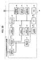
- FIGS. 3A and 3B a description is made for an information processing system 10 capable of creating, writing, and reading a system file image according to a preferred embodiment of the present invention. It is to be noted that the connections shown in FIGS. 3A and 3B represent flows of signals or information, rather than the physical connections.
- the information processing system 10 includes a host apparatus 50 (FIG. 3A) and an optical disc apparatus 20 (FIG. 3B).
- the host apparatus 50 connected to the optical disc apparatus 20, controls an entire operation of the information processing system 10.
- the host apparatus 50 creates a system file image representing user data, transfers it to the optical disc apparatus 20, and causes the optical disc apparatus 20 to record it onto an optical disc 15.
- the host apparatus 50 causes the optical disc apparatus 20 to read out a system file image of user data from the optical disc 15.
- the optical disc apparatus 20 includes a spindle motor 22, an optical pickup device 23, a laser controller 24, an encoder 25, a motor driver 27, a signal processor 28, a servo controller 33, a buffer memory 34, a buffer manager 37, a communication interface 38, a flash memory 39, a CPU (central processing unit) 40, and a RAM (random access memory) 41.
- the optical disc 15 includes any kind of optical media, such as CDs and DVDs, and it can be mounted on the optical disc apparatus 20.
- the optical disc 15 may be blank or may contain data.
- the optical disc apparatus 20 can read data from the optical disc 15 or write data onto the optical disc 15.
- the data includes, for example, user data and a system file image corresponding to the user data.
- the spindle motor 22 causes the optical disc 15 to rotate at a predetermined speed.
- the optical pickup device 23 irradiates a laser beam onto the recording surface of the optical disc 15.
- the optical pickup device 23 includes a light source 24a, a collimator lens 24b, a beam splitter 24c, an objective lens 24d, a detecting lens 24e, a photodetector PD, and a driving mechanism (not shown).
- the light source 24a includes a semiconductor laser LD, capable of emitting a laser beam having a wavelength ranging from 780 nm to 830 nm, preferably 780 nm, in a direction indicated as "X" in FIG. 4.
- the collimator lens 24b arranged on the right side (in the X direction) of the light source 24a, receives the light emitted from the light source 24a and forms it into a parallel light beam.
- the parallel light beam then passes through the beam splitter 24c, arranged on the right side (in the X direction) of the collimated lens 24b, toward the objective lens 24d, arranged on the right side (in the X direction) of the beam splitter 24c.
- the objective lens 24d condenses the parallel light and directs it toward the optical disk 15, placed substantially near the focal point of the objective lens 24d. As a result, an optical spot image is formed on the recording surface of the optical disc 15.
- the objective lens 24d further condenses light reflected at the optical disc 15 and directs it toward the beam splitter 24c.
- the beam splitter 24c directs the reflected light toward the detecting lens 24e, arranged near the beam splitter 24c, in the direction opposite to a direction Z in FIG. 4.
- the detecting lens 24e condenses the reflected light toward the photodetector PD to form an optical spot image on the light receiving surface of the photodetector PD.
- the photodetector PD outputs a current signal to the signal processor 28, according to the optical spot image.
- the signal processor 28 includes an I/V (inverting) amplifier 28a, a servo signal detector 28b, a wobble signal detector 28c, an RF (radio frequency) signal detector 28d, and a decoder 28e.
- the I/V amplifier 28a receives the current signal from the photodetector PD, and converts it to a voltage signal, after amplifying it with a predetermined gain.
- the servo signal detector 28b generates servo signals, including, for example, a focusing error signal and a tracking error signal, based on the voltage signal, and outputs them to the servo controller 33 (FIG. 3B).
- the wobble signal detector 28c generates a wobble signal based on the voltage signal, and output it to the decoder 28e.
- the RF signal detector 28d generates an RF signal based on the voltage signal, and outputs it to the decoder 28e.
- the decoder 28e extracts address information and/or synchronized information from the wobble signal.
- the extracted address information is output to the CPU 40 (FIG. 3B), while the extracted synchronized information is output to the encoder 25 (FIG. 3B).
- the decoder 28e decodes the RF signal and corrects its errors, if existed, and stores the decoded RF signal as reproduced data in the buffer memory 34 (FIG. 3B) via the buffer manager 37 (FIG. 3B). At this time, address information contained in the RF signal is also output to the CPU 40 (FIG. 3B).
- the servo controller 33 which has received the servo signals, controls the optical pickup device 23 through the driving mechanism.
- the servo controller 33 generates a focusing control signal based on the focusing error signal, and a tracking control signal based on the tracking error signal. These control signals are output to the motor driver 27 when the servo controller 33 is activated by the CPU 40. When the servo controller 33 is not activated, no control signals are output to the motor driver 27.
- the motor driver 27 outputs a focusing driving signal to the optical pickup device 23 according to the focusing control signal.
- a focusing actuator (not shown) of the driving mechanism controls the focusing direction (in the X direction and the direction opposite to the X direction of FIG. 4) of the objective lens 24d (FIG. 4).
- the motor driver 27 also outputs a tracking driving signal to the optical pickup device 23 according to the tracking control signal.
- a tracking actuator (not shown) of the driving mechanism controls the tracking direction (in the Z direction and the direction opposite to the Z direction of FIG. 4) of the objective lens 24d (FIG. 4).
- the motor driver 27 outputs driving signals for driving, respectively, the spindle motor 22, and a seek motor (not shown) of the driving mechanism, according to control signals generated by the CPU 40.
- the buffer memory 34 includes a data buffer area and a program variable area.
- the data buffer area temporarily stores data (“reproduced data”) that has been read out from the optical disc 15, and data (“recorded data”) to be recorded onto the optical disc 15.
- the program variable area stores variable data to be used by the CPU 40.
- the buffer manager 37 manages the amount of data stored in the buffer memory 34, by checking input or output of data. For example, when the amount of data in the buffer memory 34 reaches a predetermined level, the buffer manager 37 notifies the CPU 40 that no more data can be stored in the buffer memory 34.
- the encoder 25 reads out the recorded data accumulated in the buffer memory 34 via the buffer manager 37. After applying modulation and adding an error correction code to the recorded data, the encoder 25 generates a writing signal based on the recorded data. The writing signal is then output to the laser controller 24.
- the laser controller 24 generates a driving signal for driving the semiconductor laser LD of the optical pickup device 23, according to a luminance characteristic of the semiconductor laser LD and the writing signal received from the encoder 25. In other words, the laser controller 24 controls the power of the laser beam emitted from the optical pickup device 23.
- the communication interface 38 allows a two-way communication between the optical disc apparatus 20 and the host apparatus 50.
- the communication interface 38 may be in compliance with the ATAPI (AT Attachment Packet Interface), ATA (AT Attachment), SCSI (Small Computer System Interface), USB (Universal Serious Bus) 1.0, USB 2.0, IEEE 1394, IEEE 802.3, Serial ATA, Serial ATAPI, for example.
- ATAPI AT Attachment Packet Interface
- ATA AT Attachment
- SCSI Small Computer System Interface
- USB Universal Serious Bus
- the flash memory 39 includes a program area and a data area.
- the program area stores various programs that are readable to the CPU 40, including a program for creating a system file image in the HDD 54 ("image creating program"), a program for writing a system file image onto the optical disc 15 (“image writing program”), and a program for reading a system file image from the optical disc 15 (“image reading program”).
- the data area stores information, including information regarding the luminance characteristic of the semiconductor laser LD, the seek operation of the optical pickup device 23, and recording conditions, for example.
- the CPU 40 controls an entire operation of the optical disc apparatus 20, according to the programs stored in the program area of the flash memory 39.
- the CPU 40 further stores necessary data in the program variable area of the buffer memory 34 and/or the RAM 41.
- the host apparatus 50 includes a main controller 52, a RAM 53, a HDD (hard disk drive) 54, an input device 55, a display device 56, and a communication interface 57.
- the main controller 52 includes an MPU (main processing unit) 52a and a main memory 52b, for example, and functions as a microprocessor for controlling an entire operation of the host apparatus 50.
- the main controller 52 has a function of storing necessary data in the RAM 53.
- the communication interface 57 allows a two-way communication between the optical disc apparatus 20 and the host apparatus 50.
- the communication interface 57 is preferably in compliance with the interface standard used by the communication interface 38 of FIG. 3B. Thus, it may be in compliance with the ATAPI (AT Attachment Packet Interface), ATA (AT Attachment), SCSI (Small Computer System Interface), USB (Universal Serious Bus) 1.0, USB 2.0, IEEE 1394, IEEE 802.3, Serial ATA, Serial ATAPI, for example.
- ATAPI AT Attachment Packet Interface
- ATA AT Attachment
- SCSI Small Computer System Interface
- USB Universal Serious Bus
- the HDD 54 stores various programs, including the image creating program and the image writing program, in a format readable to the MPU 52a.
- the HDD 54 further stores user data.
- the display device 56 includes a display (not shown), such as a CRT (cathode ray tube), LCD (liquid crystal display), PDP (plasma display panel), for example.
- the display device 56 displays various information output from the main controller 52.
- the input device 55 includes a keyboard, mouse, tablet, tracking ball, lighting pen, and touch panel, for example.
- the input device 55 notifies the MPU 52a of various information input by a user. Such information may be input by wired or wireless means.
- the display device 56 and the input device 55 may be integrated into one device, such as a CRT with a touch panel.
- the optical disc apparatus 20 can write user data stored in the host apparatus 50 onto the optical disc 15.
- a system file image representing the user data is recorded onto the optical disc 15, such that the user data can be read by a wide variety of operating systems.
- FIG. 6 an exemplary operation performed by the host apparatus 50 of writing user data onto the optical disc 15 is explained.
- the optical disc 15 contains no data, i.e., it is a blank disc.
- the user data is previously stored in the HDD 54 as a user file F in a subdirectory DIR 2 under a root directory as shown in FIG. 7.
- the root directory additionally includes a subdirectory DIR 1.
- the steps shown in FIG. 6 are performed by the main controller 52 according to the image creating program and the image writing program. More specifically, when a user selects the user file F stored in the HDD 54, and instructs the host apparatus 50 to write the user file F onto the optical disc 15, the image creating program and the image writing program are loaded from the HDD 54 onto the main memory 52b. At the same time, the MPU 52a starts operating according to those programs.
- Step S401 the main controller 52 obtains various kinds of information regarding the user file F (hereinafter, collectively referred to as "file/directory information”), including information regarding its format, directory hierarchy, and/or length.
- file/directory information information regarding its format, directory hierarchy, and/or length.
- Step S403 the main controller 52 constructs a virtual directory structure in the RAM 53, using the file/directory information obtained in the previous step.
- the virtual directory structure corresponds to the directory hierarchy of the user file F shown in FIG. 7.
- Step S405 the main controller 52 reserves a space for a system file image in the HDD 54, according to the virtual directory structure.
- Step S407 the main controller 52 creates the system file image in the HDD 54, according to a format corresponding to at least one operating system that the user intends to use for reproducing the user file F.
- a format corresponding to at least one operating system that the user intends to use for reproducing the user file F For example, if the user intends to use the Windows, a system file image corresponding to the Joliet standard is created.
- a system file image corresponding to the Joliet/Rock Ridge standard is created.
- a system file image corresponding to the Joliet/HFS standard is created, preferably with the Joliet/Rock Ridge support.
- Step S409 the main controller 52 stores the user file F in the HDD 54.
- Step S411 the main controller 52 issues a command to the optical disc apparatus 20, requesting the optical disc apparatus 20 to write the system file image and the user file F.
- Step S413 the main controller 52 outputs the system file image and the user file F to the optical disc apparatus 20.
- Step S415 the main controller 52 determines whether the recording is completed. If it is completed, the operation ends, otherwise, the operation repeats Step S415.
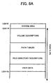
- FIGS. 8A to 8C illustrate an exemplary structure of an optical disc volume of the optical disc 15.
- the user data namely, the user file F is recorded onto the optical disc 15, in compliance with the Joliet standard, using the image processing system 10.
- FIGS. 8A to 8C are substantially similar to the structure shown in FIGS. 1A to 1C, except for the contents of information stored in the group of descriptors.
- the path tables and the file/directory descriptors shown in FIG. 8A include less amount of information than the corresponding descriptors shown in FIG. 1A.
- the ISO path table and the ISO root directory shown in FIG. 8B include less amount of information than the corresponding descriptors shown in FIG. 1B.
- the ISO subdirectory is not included in the disc volume of FIG. 8B.
- the PVD starts at the LBA of 16.
- the ISO path table starts at the LBA of N1.
- the Joliet path table starts at the LBA of N2.
- the ISO root directory starts at the LBA of N3.
- the Joliet root directory starts at the LBA of N4.
- the Joliet subdirectory starts at the LBA of N5.
- the user data namely, the user file F is stored at the LBA of N7.
- the PVD stores the number ("N1") assigned to the LBA starting the ISO path table, as a link to the ISO path table.
- the PVD further stores the number (“N3") assigned to the LBA starting the ISO root directory, as a link to the ISO root directory.
- the SVD stores the number ("N2") assigned to the LBA starting the Joliet path table, as a link to the Joliet path table.
- the SVD further stores the number ("N4") assigned to the LBA starting the Joliet root directory, as a link to the Joliet root directory.
- the ISO path table stores the number ("N3") assigned to the LBA starting the ISO root directory, as a link to the ISO root directory. However, the ISO path table does not contain information regarding the ISO subdirectory.
- the Joliet path table stores the number ("N4") assigned to the LBA starting the Joliet root directory, as a link to the Joliet root directory.
- the Joliet path table further stores the number assigned to the LBA starting the Joliet subdirectory, as a link to the Joliet subdirectory. Particularly, in this example, the number ("N5") assigned to the LBA starting the subdirectory JOLIET DIR 1, and the number (“N6") assigned to the LBA starting the subdirectory JOLIET DIR 2 are stored.
- the ISO root directory contains dummy information.
- the dummy information may be referred to as any kind of information having no effect on the operation, and may be expressed as "0" values.
- the Joliet root directory stores the number assigned to the LBA starting the Joliet subdirectory, as a link to the Joliet subdirectory. Particularly, in this example, the number ("J5") assigned to the LBA starting the subdirectory JOLIET DIR1, and the number (“J6") assigned to the LBA starting the subdirectory JOLIET DIR2 are stored.
- the subdirectory JOLIET DIR 1 stores information regarding the contents of the subdirectory JOLIET DIR 1. Particularly, it stores dummy information, having 0 values, for example.
- the subdirectory JOLIET DIR 2 stores information regarding the contents of the subdirectory JOLIET DIR 2. Particularly, in this example, it stores the length of the user file F, as well as the number ("N7") assigned to the LBA starting the user file F, in compliance with the Joliet standard.
- the group of descriptors shown in any one of FIGS. 8A to 8C contains less amount of space in the data area, compared to the group of descriptors shown in any one of FIGS. 1A to 1C.
- FIG. 9 illustrates an exemplary operation performed by the main controller 52 of creating a system file image corresponding to the disc volume shown in FIG. 8C.
- Step S417 which starts preferably after Step S407 of FIG. 6, the main controller 52 creates the PVD, which stores the LBA of the ISO path table and the LBA of the ISO root directory.
- Step S419 the main controller 52 creates the ISO path table, which stores only information regarding the ISO root directory, including the LBA of the ISO root directory.
- Step S420 the main controller 52 creates the Joliet path table, which stores the LBA of the Joliet root directory, the LBA of the subdirectory JOLIET DIR 1, and the LBA of the subdirectory JOLIET DIR 2.
- Step S421 the main controller 52 creates the ISO root directory, containing dummy information.
- Step S422 the main controller 52 creates the Joliet root directory, which stores the LBA of the subdirectory JOLIET DIR 1, and the LBA of the subdirectory JOLIET DIR 2.
- Step S423 the main controller 52 creates the Joliet subdirectory, including the subdirectory JOLIET DIR 1 and the subdirectory JOLIET DIR 2.
- the subdirectory JOLIET DIR 1 stores dummy information.
- the subdirectory JOLIET DIR 2 stores at least the length of the user file F, as well as the LBA of the user file F. Then, the operation moves to Step S409 of FIG. 6.
- the present invention may be applied to other cases, including the case of creating a system file image defined in the Joliet/Rock Ridge standard and Joliet/HFS standard.
- the optical disc apparatus 20 of recording user data is explained with reference to FIGS. 10A and 10B.
- the user file F is written onto the optical disc volume 20 under control of the host apparatus 50.
- the steps shown in FIGS. 10A and 10B are performed by the CPU 40 according to the image writing program. More specifically, when the CPU 40 receives the command generated in Step S411 (FIG. 6) from the main controller 52, the image writing program is loaded from the flash memory 39 onto the RAM 41. At the same time, the CPU 40 starts operating according to the image writing program.
- Step S501 of FIG. 10A the CPU 40 notifies the signal processor 28 that the command has been issued. Further, the CPU 40 instructs the buffer manager 37 to receive the system file image and the user file F and store them into the buffer memory 34.
- Step S503 of FIG. 10A the CPU 40 generates a control signal and outputs it to the motor driver 27, as mentioned above.
- the motor driver 27 controls the rotation of the spindle motor 22. In this way, the optical disc 15 rotates at a predetermined recording speed.
- Step S505 of FIG. 10A the CPU 40 determines whether the rotation of the optical disc 15 has reached the predetermined recording speed. If the rotation has reached the predetermined recording speed, the operation moves to Step S507, otherwise, the operation moves to Step S503 to further control the rotation of the spindle motor 22.
- Step S507 of FIG. 10A the CPU 40 activates the servo controller 33.
- the servo controller 33 then controls the optical pickup device 23 through the focusing and tracking control signals, in the manner described referring to FIG. 3.
- Step S509 of FIG. 10A the CPU 40 runs an optimum power control to determine the optimum laser power for recording.
- the CPU 40 may continuously run the optimum power control during the entire recording operation.
- Step S511 of FIG. 10A the CPU 40 extracts a current address from the address information received from the decoder 28e, and a target address from the received command.
- Step S513 of FIG. 10A the CPU 40 calculates the address difference between the current address and the target address.
- Step S515 of FIG. 10B the CPU 40 determines whether a seeking operation is needed based on the calculated address difference. If it is determined that the seeking operation is needed, the operation moves to Step S517 of FIG. 10B, otherwise, the operation moves to Step S519 of FIG. 10B.
- the CPU 40 can determine the need of seeking operation by referring to a predetermined threshold value stored in the flash memory 39. If the address difference exceeds the threshold value, the CPU 40 may determine that the seeking operation is needed.
- Step S517 of FIG. 10B the CPU 40 generates a seeking control signal to the motor driver 27, according to the address difference. With this seeking control signal, the seeking motor starts the seeking operation.
- Step S519 of FIG. 10B the CPU 40 determines whether the current address matches with the target address. If they are matched, the operation moves to Step S521 of FIG. 10B, otherwise, the operation moves to Step S523 of FIG. 10B to obtain a current address and repeat Step S519 of FIG. 10B.
- Step S521 of FIG. 10B the CPU 40 instructs the encoder 25 to start recording the system file image and the user data onto the optical disc 15. With this instruction, the encoder 25 starts the recording operation via the laser controller 24 and the optical pickup device 23.
- Step S525 of FIG. 10B the CPU 40 determines whether the system file image and the user data are recorded on the optical disc 15. If it is determined that they are recorded, the operation moves to Step S527 of FIG. 10B, otherwise, the operation repeats Step S525 of FIG. 10B.
- Step S527 the CPU 40 notifies the host apparatus 50 that the recording operation has completed, and ends the recording operation of FIGS. 10A and 10B.
- the optical disc 15 may be a multisession disc having data previously stored.
- FIG. 11 illustrates an exemplary operation of writing additional user data onto the optical disc 15.
- the optical disc 15 is a multisession disc containing user data in its first session, particularly, a first user file F1 having a directory hierarchy shown in FIG. 12. Further, the user data to be added is referred to as a second user file F2, having a directory hierarchy shown in FIG. 12.
- the steps shown in FIG. 11 are performed by the main controller 52 according to the image creating program and the image writing program. More specifically, when the user selects the second user file F2 stored in the HDD 54, and instructs the host apparatus 50 to write the second user file F2 onto the second session of the optical disc 15, the image creating program and the image writing program are loaded from the HDD 54 onto the main memory 52b. At the same time, the MPU 52a starts operating according to those programs.
- Step S601 the main controller 52 obtains file/directory information of the first user file F1. Such file/directory information may be read out from the first session of the optical disc 15.
- Step S602 the main controller 52 obtains file/directory information of the second user file F2, from the HDD 54.
- Step S603 the main controller 52 constructs a virtual directory structure in the RAM 53, using the file/directory information regarding the second user file F2, obtained in the previous step.
- the virtual directory structure corresponds to the directory hierarchy shown in FIG. 12.
- Step S605 the main controller 52 reserves a space for a system file image in the HDD 54, according to the virtual directory structure.
- Step S607 the main controller 52 creates the system file image in the HDD 54, according to a format corresponding to at least one operating system that the user intends to use, in a substantially similar manner described referring to Step S407.
- the format selected in this step for the second session does not have to match with a format used in the first session, as long as the both formats comply requirements of the ISO standard.
- Step S609 the main controller 52 stores the second user file F2 in the HDD 54.
- Step S611 the main controller 52 issues a command to the optical disc apparatus 20, requesting the optical disc apparatus 20 to write the system file image and the second user file F2.
- Step S613 the main controller 52 outputs the system file image and the second user file F2 to the optical disc apparatus 20.
- Step S615 the main controller 52 determines whether the recording is completed. If it is completed, the operation ends, otherwise, the operation repeats Step S613.
- FIGS. 13A to 13C illustrate an exemplary structure of an optical disc volume of the optical disc 15.
- the user data namely the user file F2 is additionally recorded onto the optical disc 15, in compliance with the Joliet standard, after closing of the first session containing the user file F1, using the image processing system 10.
- the disc volume includes a system area and a data area.
- the system area starts at the LBA of N, which represents the end of the first session.
- the data area starts at the LBA of N+16, and includes volume descriptors, path tables, and file/directory descriptors.
- the data area further stores the actual user data, i.e., the user file F2.
- the volume descriptors include a PVD, a SVD, and a VDT.
- the path tables include a path table defined in the Joliet standard ("Joliet path table").
- the file/directory descriptors include a root directory descriptor defined in the Joliet standard ("Joliet root directory"), and a subdirectory descriptor defined in the Joliet standard (“Joliet subdirectory”).
- the PVD starts at the LBA of N+16.
- the Joliet root directory starts at the LBA of N11.
- the Joliet path table starts at the LBA of N12.
- the Joliet subdirectory starts at the LBA of N13.
- the PVD copies contents of information from the PVD of the first session of the optical disc 15.
- the first session may contain information substantially similar to the one shown in FIG. 8C.
- the PVD of the first session stores the number (“N1") assigned to the LBA starting the ISO path table of the first session, as a link to the ISO path table of the first session.
- the PVD of the first session further stores the LBA ("N3") assigned to the LBA starting the ISO root directory, as a link to the ISO root directory of the first session.
- the PVD of the second session may be created by copying such information stored in the PVD of the first session.
- the SVD stores the number ("N11") assigned to the LBA starting the Joliet path table, as a link to the Joliet path table.
- the SVD further stores the number (“N12”) assigned to the LBA starting the Joliet root directory, as a link to the Joliet root directory.
- the Joliet path table stores the number ("N12") assigned to the LBA starting the Joliet root directory.
- the Joliet path table further stores the number assigned to the LBA starting the Joliet subdirectory.
- the number (“N13") assigned to the LBA starting the subdirectory DIR1 defined in the Joliet standard (“JOLIET DIR 1"), and the number (“N14") assigned to the LBA starting the subdirectory DIR2 defined in the Joliet standard (“JOLIET DIR 2") are stored.
- the Joliet root directory stores the number assigned to the LBA starting the Joliet subdirectory, as a link to the Joliet subdirectory. Particularly, in this example, the number (“N13") assigned to the LBA starting the subdirectory JOLIET DIR1, and the number (“N14") assigned to the LBA starting the subdirectory JOLIET DIR2 are stored.
- the subdirectory JOLIET DIR 1 stores the length of the user file F1, as well as the number ("N7" in FIG. 8C, for example) assigned to the LBA starting the user file F1, in compliance with the Joliet standard. Such information may be obtained by referring to the first session of the optical disc 15.
- the subdirectory JOLIET DIR 2 stores the length of the user file F2, as well as the number ("N15") assigned to the LBA starting the user file F2, in compliance with the Joliet standard.
- the group of descriptors shown in any one of FIGS. 13A to 13C contains less amount of space in the data area, when compared to the group of the descriptors shown in any one of FIGS. 1A to 1C.
- FIG. 14 illustrates an exemplary operation performed by the main controller 52 of creating a system file image corresponding to the disc volume shown in FIG. 13C.
- Step S617 which starts preferably after Step S607 of FIG. 11, the main controller 52 copies the PVD of the first session from the optical disc 15.
- Step S619 the main controller 52 creates the Joliet path table, which stores the LBA of the Joliet root directory, the LBA of the subdirectory JOLIET DIR 1, and the LBA of the subdirectory JOLIET DIR 2.
- Step S621 the main controller 52 creates the Joliet root directory, which stores the LBA of the subdirectory JOLIET DIR 1, and the LBA of the subdirectory JOLIET DIR 2.
- Step S623 the main controller 52 creates the Joliet subdirectory, including the subdirectory JOLIET DIR 1 and the subdirectory JOLIET DIR 2.
- the subdirectory JOLIET DIR 1 stores at least the length of the user file F1 as well as the LBA of the user file F1.
- the subdirectory JOLIET DIR 2 stores at least the length of the user file F2 as well as the LBA Of the user file F2.
- the present invention may be applied to other cases, including the case of creating a system file image defined in the Joliet/Rock Ridge standard and Joliet/HDF standard.
- the system file image created by the host apparatus 50 may be recorded onto the optical disc 15 by the optical disc apparatus 20, in a manner substantially similar to the one shown in FIGS. 10A and 10B.
- the information processing system 10 may read a system file image from the optical disc 15.
- FIG. 15 illustrates an exemplary operation performed by the host apparatus 50 of reading user data from the optical disc 15.
- the host apparatus 50 reads the user file F1 from the optical disc 15, containing the user file F1 and the user file F2, in the directory hierarchy shown in FIG. 12.
- the optical disc 15 contains a disc volume having the structure shown in any one of FIGS. 13A to 13C. Further, the host apparatus 50 operates under the operating system, capable of reading the Joliet standard.
- the steps shown in FIG. 15 are performed by the main controller 52 according to the image reading program. More specifically, when a user selects the user file F1 stored in the HDD 54, and instructs the host apparatus 50 to read the user file F1 from the optical disc 15, the image reading program is loaded from the HDD 54 onto the main memory 52b. At the same time, the MPU 52a starts operating according to those programs.
- Step S701 the main controller 52 obtains the file/directory information of the user file F1 from the optical disc 15.
- Step S703 the main controller 52 extracts the LBA ("N11" in FIG. 13C) of the Joliet path table from the SVD of the second session.
- Step S705 the main controller 52 extracts the LBA ("N13" in FIG. 13C) of the subdirectory JOLIET DIR 1, which includes the user file F1, from the Joliet path table.
- Step S707 the main controller 52 extracts the length of the user file F1 and the LBA ("N7" in FIG. 8C) of the user file F1, from the subdirectory JOLIET DIR 1.
- Step S709 the main controller 52 issues a command to the optical disc apparatus 20 of requesting the optical disc apparatus 20 to reproduce the user file F1.
- Step S711 the main controller 52 displays the user file F1 on the display device 56.
- Step S713 the main controller 52 determines whether the reading operation has been completed. If it is completed, the operation ends, otherwise, the operation goes back to Step S711.
- FIGS. 16A and 16B are performed by the CPU 40 according to the image reading program. More specifically, when the CPU 40 receives the command generated in Step S709 (FIG. 15) from the main controller 52, the image reading program is loaded from the flash memory 39 onto the RAM 41. At the same time, the CPU 40 starts operating according to the image reading program.
- Step S801 of FIG. 16A the CPU 40 notifies the signal processor 28 that the command has been issued.
- Step S803 of FIG. 16A the CPU 40 generates a control signal and outputs it to the motor driver 27.
- the motor driver 27 controls the rotation of the spindle motor 22. In this way, the optical disc 15 rotates at a predetermined reading speed.
- Step S805 of FIG. 16A the CPU 40 determines whether the rotation of the optical disc 15 has reached the predetermined reading speed. If the rotation has reached the predetermined reading speed, the operation moves to Step S807, otherwise, the operation moves to Step S803 to further control the rotation of the spindle motor 22.
- Step S807 of FIG. 16A the CPU 40 activates the servo controller 33.
- the servo controller 33 then controls the optical pickup device 23 through the focusing and tracking control signals, in the manner described referring to FIG. 3.
- Step S811 of FIG. 16A the CPU 40 extracts a current address from the address information received from the decoder 28e, and a target address from the received command.
- Step S813 of FIG. 16A the CPU 40 calculates the address difference between the current address and the target address.
- Step S815 of FIG. 16B the CPU 40 determines whether a seeking operation is needed based on the calculated address difference. If it is determined that the seeking operation is needed, the operation moves to Step S817 of FIG. 16B, otherwise, the operation moves to Step S819 of FIG. 16B. The determination may be made in a similar manner as descried referring to Step S515 of FIG. 10B.
- Step S817 of FIG. 16B the CPU 40 generates a seeking control signal to the motor driver 27, according to the address difference. With this seeking control signal, the seeking motor starts the seeking operation.
- Step S819 of FIG. 16B the CPU 40 determines whether the current address matches with the target address. If they are matched, the operation moves to Step S821 of FIG. 16B, otherwise, the operation moves to Step S823 of FIG. 16B to obtain a current address and repeat Step S819 of FIG. 16B.
- Step S821 of FIG. 16B the CPU 40 instructs the signal processor 28 to start reproducing the user data, i.e., the user file F1, stored on the optical disc 15.
- the signal processor 28 starts the reading operation and stores the read data onto the buffer memory 34.
- the buffer memory 34 transfers the received data, sector by sector, to the host apparatus 50 via the communication interface 38.
- Step S825 of FIG. 16B the CPU 40 determines whether all the user data has been read from the optical disc 15. If it is determined that it has been read, the operation moves to Step S827 of FIG. 16B, otherwise, the operation repeats Step S825 of FIG. 16B.
- Step S827 the CPU 40 notifies the host apparatus 50 that the reading operation has completed, and ends the reading operation of FIGS. 16A and 16B.
- the image processing system 10 can still read the user file F1, using the ISO standard. In such a case, necessary information is added to the group of descriptors defined in the ISO standard.
- the host apparatus 50 refers to the group of descriptors defined in the HFS standard, by using a pointer stored in the system area, as shown in FIG. 17.
- the HFS specification is hereby incorporated by reference.
- the group of descriptors defined in the Joliet standard is stored preferably in the first session.
- the host apparatus 50 refers to the group of descriptors defined in the UDF standard, by using a pointer stored in the system area, as shown in FIG. 18.
- the UDF specification is hereby incorporated by reference.
- the group of descriptors defined in the Joliet standard is stored preferably in the first session.
- any one of the image creating, image writing, and image reading programs may be stored in any kind of storage device, including optical discs, magneto optical discs, memory card, flexible discs, etc. Further, any one of the above programs may be downloaded from another storage device via a network, including an LAN, an intranet, the Internet, etc.
- the optical discs may include, for example, a hybrid disc including a RAM section and a ROM section. If the hybrid disc is used as the storage device, any one of the programs may be written in the ROM section. In such a case, user data and the corresponding system file image may be written in the ROM section.
- the image processing system 10 it is not required for the image processing system 10 to perform all the functions including creating, writing, and reading.
- the image processing system 10 needs to perform at least one of the described functions.
- the structures and operations described referring to the image processing system 10 are provided for the descriptive purpose. Thus, different structures and different operations may be applied to the image processing system 10, as will be apparent to those skilled in the art, within the scope of this disclosure and appended claims.
Landscapes
- Engineering & Computer Science (AREA)
- Theoretical Computer Science (AREA)
- Human Computer Interaction (AREA)
- Physics & Mathematics (AREA)
- General Engineering & Computer Science (AREA)
- General Physics & Mathematics (AREA)
- Multimedia (AREA)
- Signal Processing (AREA)
- Signal Processing For Digital Recording And Reproducing (AREA)
- Management Or Editing Of Information On Record Carriers (AREA)
- Information Retrieval, Db Structures And Fs Structures Therefor (AREA)
Applications Claiming Priority (2)
| Application Number | Priority Date | Filing Date | Title |
|---|---|---|---|
| JP2003332952 | 2003-09-25 | ||
| JP2003332952A JP2005100095A (ja) | 2003-09-25 | 2003-09-25 | イメージデータ作成方法、記録方法、プログラム及び記録媒体、光ディスク、並びに情報記録システム |
Publications (2)
| Publication Number | Publication Date |
|---|---|
| EP1519261A2 true EP1519261A2 (fr) | 2005-03-30 |
| EP1519261A3 EP1519261A3 (fr) | 2008-10-29 |
Family
ID=34191475
Family Applications (1)
| Application Number | Title | Priority Date | Filing Date |
|---|---|---|---|
| EP04255892A Withdrawn EP1519261A3 (fr) | 2003-09-25 | 2004-09-27 | Méthode, appareil, système et programme pour créer, enregistrer et lire une image de système sous forme de fichier, un support stockant le programme et un support stockant l'image de système sous forme de fichier |
Country Status (4)
| Country | Link |
|---|---|
| US (1) | US20050071351A1 (fr) |
| EP (1) | EP1519261A3 (fr) |
| JP (1) | JP2005100095A (fr) |
| KR (1) | KR100653658B1 (fr) |
Cited By (2)
| Publication number | Priority date | Publication date | Assignee | Title |
|---|---|---|---|---|
| EP2375418A3 (fr) * | 2010-04-01 | 2012-04-04 | Sony Corporation | Procédé de création, dispositif de création et programme |
| CN110827861A (zh) * | 2018-08-13 | 2020-02-21 | 希捷科技有限公司 | 使用多个卷提供复制的多致动器驱动器 |
Families Citing this family (3)
| Publication number | Priority date | Publication date | Assignee | Title |
|---|---|---|---|---|
| CN101057288B (zh) | 2004-11-09 | 2010-12-22 | 汤姆森许可贸易公司 | 把内容绑定到可移动存储器上的方法和装置 |
| JP2008099027A (ja) * | 2006-10-12 | 2008-04-24 | Canon Inc | 信号処理装置、撮像装置、及び信号処理方法 |
| CN116778975B (zh) * | 2023-05-29 | 2024-03-12 | 上海沪方软件有限公司 | 光盘追加刻录的方法、装置、电子设备及可读存储介质 |
Family Cites Families (13)
| Publication number | Priority date | Publication date | Assignee | Title |
|---|---|---|---|---|
| JP2827495B2 (ja) * | 1990-10-22 | 1998-11-25 | 松下電器産業株式会社 | 情報媒体の記録方法、情報再生方法および情報再生装置 |
| JPH07168749A (ja) * | 1993-10-18 | 1995-07-04 | Sony Corp | 情報管理方法、データ記録媒体、データ記録方法、情報検索方法、情報検索装置 |
| JP3492800B2 (ja) * | 1995-02-17 | 2004-02-03 | 富士通株式会社 | 光記録装置及び再生レーザパワー設定方法 |
| JPH0997490A (ja) * | 1995-07-21 | 1997-04-08 | Sony Corp | カメラ記録装置、カメラ再生装置、及び記録装置 |
| JP3546654B2 (ja) * | 1997-08-07 | 2004-07-28 | 株式会社日立製作所 | 情報記録装置及び情報記録方法 |
| KR100252046B1 (ko) * | 1997-11-11 | 2000-04-15 | 윤종용 | 광 디스크 시스템에서의 트랙킹 및 포커싱 서보 제어장치 |
| JPH11232838A (ja) | 1998-02-16 | 1999-08-27 | Matsushita Electric Ind Co Ltd | 光ディスク、光ディスク記録装置、及び光ディスク読取装置 |
| US7346920B2 (en) * | 2000-07-07 | 2008-03-18 | Sonic Solutions, A California Corporation | System, method and article of manufacture for a common cross platform framework for development of DVD-Video content integrated with ROM content |
| EP1096496A3 (fr) * | 1999-11-01 | 2004-04-28 | Adaptec, Inc. | Interface pour des programmes d'apllications d'élaboration d'images |
| JP3607153B2 (ja) * | 2000-02-28 | 2005-01-05 | シャープ株式会社 | ファイル管理方法及び装置 |
| JP2001243102A (ja) * | 2000-02-29 | 2001-09-07 | Sony Corp | 記録装置および方法、ならびに、記録媒体 |
| US6618329B2 (en) * | 2001-08-28 | 2003-09-09 | Hanpin Electron Co., Ltd. | Digital audio signal player having a simulated analogue record |
| US6963952B1 (en) * | 2002-07-19 | 2005-11-08 | Sonic Solutions, Inc. | Multi-session optical media and methods for recording |
-
2003
- 2003-09-25 JP JP2003332952A patent/JP2005100095A/ja active Pending
-
2004
- 2004-09-24 KR KR1020040076851A patent/KR100653658B1/ko not_active Expired - Fee Related
- 2004-09-24 US US10/948,153 patent/US20050071351A1/en not_active Abandoned
- 2004-09-27 EP EP04255892A patent/EP1519261A3/fr not_active Withdrawn
Cited By (4)
| Publication number | Priority date | Publication date | Assignee | Title |
|---|---|---|---|---|
| EP2375418A3 (fr) * | 2010-04-01 | 2012-04-04 | Sony Corporation | Procédé de création, dispositif de création et programme |
| US8712223B2 (en) | 2010-04-01 | 2014-04-29 | Sony Corporation | Authoring method, authoring device and program |
| CN110827861A (zh) * | 2018-08-13 | 2020-02-21 | 希捷科技有限公司 | 使用多个卷提供复制的多致动器驱动器 |
| CN110827861B (zh) * | 2018-08-13 | 2021-04-13 | 希捷科技有限公司 | 使用多个卷提供复制的多致动器驱动器 |
Also Published As
| Publication number | Publication date |
|---|---|
| JP2005100095A (ja) | 2005-04-14 |
| KR100653658B1 (ko) | 2006-12-05 |
| EP1519261A3 (fr) | 2008-10-29 |
| KR20050030592A (ko) | 2005-03-30 |
| US20050071351A1 (en) | 2005-03-31 |
Similar Documents
| Publication | Publication Date | Title |
|---|---|---|
| JP4183553B2 (ja) | 記録方法、プログラム及び記録媒体、並びに情報記録装置 | |
| KR100313979B1 (ko) | 레코딩매체용제어장치 | |
| US20040145988A1 (en) | Method and system of creating a backup disc of a hybrid disc | |
| US7974520B2 (en) | Information recording ensuring compatibility with different types of recording media | |
| EP1519261A2 (fr) | Méthode, appareil, système et programme pour créer, enregistrer et lire une image de système sous forme de fichier, un support stockant le programme et un support stockant l'image de système sous forme de fichier | |
| US7596063B2 (en) | Defect management method, reproduction method, recording medium, information recording apparatus, and information reproduction apparatus | |
| EP1564741A1 (fr) | Méthode pour définir de l'information sur la gestion des défauts, méthode d'enregistrement, programme informatique, support d'enregistrement lisible par ordinateur et dispositif d'enregistrement, qui enregistre correctement plusieurs types d'information pour des types d'usages différents sur le même support d'enregistrement | |
| JP2008507797A (ja) | 記録担体に情報を記録する装置及び方法 | |
| EP1717805A1 (fr) | Procede de parametrage d'information de gestion des defauts, procede d'enregistrment, procede de gestion des defauts, programme; support d'enregistrement et dispositif d'enregistrement d'information | |
| KR20020053449A (ko) | 광 기록매체 상의 데이터 복사 및 이동 방법 | |
| US20050066111A1 (en) | Optical disk reproducing apparatus and optical disk reproducing method | |
| CN100573697C (zh) | 缺陷管理信息设定方法、记录方法、缺陷管理方法和信息记录装置 | |
| JP2003173626A (ja) | 情報記録再生装置 | |
| JP3913769B2 (ja) | システム | |
| JP4144893B2 (ja) | システム、データ再生方法及び情報再生装置 | |
| CN100382157C (zh) | 操作条件设置系统 | |
| JP2005293780A (ja) | 欠陥管理方法、再生方法、プログラム及び記録媒体、情報記録装置並びに情報再生装置 | |
| TW200521980A (en) | Device for and method of recording digital information signals | |
| JP3934148B2 (ja) | データ領域数決定方法、データ管理情報取得方法及び情報再生装置 | |
| JP2009521069A (ja) | データ・ファイルを取り出す装置及び方法 | |
| JPWO2007049742A1 (ja) | 情報記録装置及び方法、並びにコンピュータプログラム | |
| JP4137970B2 (ja) | 記録方法、プログラム及び記録媒体、並びに情報記録システム | |
| JP2001307035A (ja) | 記録再生装置 | |
| JPH1064066A (ja) | 光ディスク情報記録システム | |
| JP2006079763A (ja) | 処理方法、光ディスク装置、プログラム及び記録媒体 |
Legal Events
| Date | Code | Title | Description |
|---|---|---|---|
| PUAI | Public reference made under article 153(3) epc to a published international application that has entered the european phase |
Free format text: ORIGINAL CODE: 0009012 |
|
| AK | Designated contracting states |
Kind code of ref document: A2 Designated state(s): AT BE BG CH CY CZ DE DK EE ES FI FR GB GR HU IE IT LI LU MC NL PL PT RO SE SI SK TR |
|
| AX | Request for extension of the european patent |
Extension state: AL HR LT LV MK |
|
| PUAL | Search report despatched |
Free format text: ORIGINAL CODE: 0009013 |
|
| AK | Designated contracting states |
Kind code of ref document: A3 Designated state(s): AT BE BG CH CY CZ DE DK EE ES FI FR GB GR HU IE IT LI LU MC NL PL PT RO SE SI SK TR |
|
| AX | Request for extension of the european patent |
Extension state: AL HR LT LV MK |
|
| RIC1 | Information provided on ipc code assigned before grant |
Ipc: G11B 27/32 20060101ALI20080923BHEP Ipc: G11B 27/10 20060101ALI20080923BHEP Ipc: G11B 27/034 20060101ALI20080923BHEP Ipc: G11B 20/12 20060101ALI20080923BHEP Ipc: G06F 3/06 20060101AFI20050111BHEP |
|
| 17P | Request for examination filed |
Effective date: 20090427 |
|
| AKX | Designation fees paid |
Designated state(s): DE ES FR GB IT NL |
|
| 17Q | First examination report despatched |
Effective date: 20091111 |
|
| STAA | Information on the status of an ep patent application or granted ep patent |
Free format text: STATUS: THE APPLICATION IS DEEMED TO BE WITHDRAWN |
|
| 18D | Application deemed to be withdrawn |
Effective date: 20100323 |