EP1519107A1 - Fahrzeugleuchte - Google Patents
Fahrzeugleuchte Download PDFInfo
- Publication number
- EP1519107A1 EP1519107A1 EP04022491A EP04022491A EP1519107A1 EP 1519107 A1 EP1519107 A1 EP 1519107A1 EP 04022491 A EP04022491 A EP 04022491A EP 04022491 A EP04022491 A EP 04022491A EP 1519107 A1 EP1519107 A1 EP 1519107A1
- Authority
- EP
- European Patent Office
- Prior art keywords
- light
- emitting diode
- housing part
- vehicle lamp
- housing
- Prior art date
- Legal status (The legal status is an assumption and is not a legal conclusion. Google has not performed a legal analysis and makes no representation as to the accuracy of the status listed.)
- Granted
Links
- 230000003287 optical effect Effects 0.000 claims abstract description 18
- 238000001816 cooling Methods 0.000 claims abstract description 10
- 238000010168 coupling process Methods 0.000 claims description 16
- 238000005859 coupling reaction Methods 0.000 claims description 16
- 239000004065 semiconductor Substances 0.000 claims description 14
- 230000008878 coupling Effects 0.000 claims description 13
- 239000002184 metal Substances 0.000 claims description 5
- 239000011521 glass Substances 0.000 abstract 1
- 238000004519 manufacturing process Methods 0.000 description 9
- 238000009826 distribution Methods 0.000 description 3
- 239000003570 air Substances 0.000 description 2
- 238000010276 construction Methods 0.000 description 2
- 230000017525 heat dissipation Effects 0.000 description 2
- 238000004026 adhesive bonding Methods 0.000 description 1
- 239000012080 ambient air Substances 0.000 description 1
- 210000000078 claw Anatomy 0.000 description 1
- 238000005520 cutting process Methods 0.000 description 1
- 230000004907 flux Effects 0.000 description 1
- 238000002347 injection Methods 0.000 description 1
- 239000007924 injection Substances 0.000 description 1
- 239000000463 material Substances 0.000 description 1
- 239000007769 metal material Substances 0.000 description 1
- 239000007787 solid Substances 0.000 description 1
- 239000000243 solution Substances 0.000 description 1
- 238000003466 welding Methods 0.000 description 1
Images




Classifications
-
- F—MECHANICAL ENGINEERING; LIGHTING; HEATING; WEAPONS; BLASTING
- F21—LIGHTING
- F21V—FUNCTIONAL FEATURES OR DETAILS OF LIGHTING DEVICES OR SYSTEMS THEREOF; STRUCTURAL COMBINATIONS OF LIGHTING DEVICES WITH OTHER ARTICLES, NOT OTHERWISE PROVIDED FOR
- F21V29/00—Protecting lighting devices from thermal damage; Cooling or heating arrangements specially adapted for lighting devices or systems
- F21V29/50—Cooling arrangements
- F21V29/70—Cooling arrangements characterised by passive heat-dissipating elements, e.g. heat-sinks
- F21V29/74—Cooling arrangements characterised by passive heat-dissipating elements, e.g. heat-sinks with fins or blades
-
- F—MECHANICAL ENGINEERING; LIGHTING; HEATING; WEAPONS; BLASTING
- F21—LIGHTING
- F21S—NON-PORTABLE LIGHTING DEVICES; SYSTEMS THEREOF; VEHICLE LIGHTING DEVICES SPECIALLY ADAPTED FOR VEHICLE EXTERIORS
- F21S43/00—Signalling devices specially adapted for vehicle exteriors, e.g. brake lamps, direction indicator lights or reversing lights
- F21S43/10—Signalling devices specially adapted for vehicle exteriors, e.g. brake lamps, direction indicator lights or reversing lights characterised by the light source
- F21S43/13—Signalling devices specially adapted for vehicle exteriors, e.g. brake lamps, direction indicator lights or reversing lights characterised by the light source characterised by the type of light source
- F21S43/14—Light emitting diodes [LED]
-
- F—MECHANICAL ENGINEERING; LIGHTING; HEATING; WEAPONS; BLASTING
- F21—LIGHTING
- F21S—NON-PORTABLE LIGHTING DEVICES; SYSTEMS THEREOF; VEHICLE LIGHTING DEVICES SPECIALLY ADAPTED FOR VEHICLE EXTERIORS
- F21S43/00—Signalling devices specially adapted for vehicle exteriors, e.g. brake lamps, direction indicator lights or reversing lights
- F21S43/10—Signalling devices specially adapted for vehicle exteriors, e.g. brake lamps, direction indicator lights or reversing lights characterised by the light source
- F21S43/19—Attachment of light sources or lamp holders
-
- F—MECHANICAL ENGINEERING; LIGHTING; HEATING; WEAPONS; BLASTING
- F21—LIGHTING
- F21S—NON-PORTABLE LIGHTING DEVICES; SYSTEMS THEREOF; VEHICLE LIGHTING DEVICES SPECIALLY ADAPTED FOR VEHICLE EXTERIORS
- F21S43/00—Signalling devices specially adapted for vehicle exteriors, e.g. brake lamps, direction indicator lights or reversing lights
- F21S43/20—Signalling devices specially adapted for vehicle exteriors, e.g. brake lamps, direction indicator lights or reversing lights characterised by refractors, transparent cover plates, light guides or filters
- F21S43/235—Light guides
- F21S43/236—Light guides characterised by the shape of the light guide
- F21S43/241—Light guides characterised by the shape of the light guide of complex shape
-
- F—MECHANICAL ENGINEERING; LIGHTING; HEATING; WEAPONS; BLASTING
- F21—LIGHTING
- F21S—NON-PORTABLE LIGHTING DEVICES; SYSTEMS THEREOF; VEHICLE LIGHTING DEVICES SPECIALLY ADAPTED FOR VEHICLE EXTERIORS
- F21S43/00—Signalling devices specially adapted for vehicle exteriors, e.g. brake lamps, direction indicator lights or reversing lights
- F21S43/20—Signalling devices specially adapted for vehicle exteriors, e.g. brake lamps, direction indicator lights or reversing lights characterised by refractors, transparent cover plates, light guides or filters
- F21S43/235—Light guides
- F21S43/242—Light guides characterised by the emission area
- F21S43/243—Light guides characterised by the emission area emitting light from one or more of its extremities
-
- F—MECHANICAL ENGINEERING; LIGHTING; HEATING; WEAPONS; BLASTING
- F21—LIGHTING
- F21S—NON-PORTABLE LIGHTING DEVICES; SYSTEMS THEREOF; VEHICLE LIGHTING DEVICES SPECIALLY ADAPTED FOR VEHICLE EXTERIORS
- F21S43/00—Signalling devices specially adapted for vehicle exteriors, e.g. brake lamps, direction indicator lights or reversing lights
- F21S43/20—Signalling devices specially adapted for vehicle exteriors, e.g. brake lamps, direction indicator lights or reversing lights characterised by refractors, transparent cover plates, light guides or filters
- F21S43/235—Light guides
- F21S43/247—Light guides with a single light source being coupled into the light guide
-
- F—MECHANICAL ENGINEERING; LIGHTING; HEATING; WEAPONS; BLASTING
- F21—LIGHTING
- F21S—NON-PORTABLE LIGHTING DEVICES; SYSTEMS THEREOF; VEHICLE LIGHTING DEVICES SPECIALLY ADAPTED FOR VEHICLE EXTERIORS
- F21S43/00—Signalling devices specially adapted for vehicle exteriors, e.g. brake lamps, direction indicator lights or reversing lights
- F21S43/30—Signalling devices specially adapted for vehicle exteriors, e.g. brake lamps, direction indicator lights or reversing lights characterised by reflectors
- F21S43/31—Optical layout thereof
- F21S43/315—Optical layout thereof using total internal reflection
-
- F—MECHANICAL ENGINEERING; LIGHTING; HEATING; WEAPONS; BLASTING
- F21—LIGHTING
- F21V—FUNCTIONAL FEATURES OR DETAILS OF LIGHTING DEVICES OR SYSTEMS THEREOF; STRUCTURAL COMBINATIONS OF LIGHTING DEVICES WITH OTHER ARTICLES, NOT OTHERWISE PROVIDED FOR
- F21V29/00—Protecting lighting devices from thermal damage; Cooling or heating arrangements specially adapted for lighting devices or systems
- F21V29/50—Cooling arrangements
- F21V29/502—Cooling arrangements characterised by the adaptation for cooling of specific components
- F21V29/507—Cooling arrangements characterised by the adaptation for cooling of specific components of means for protecting lighting devices from damage, e.g. housings
-
- F—MECHANICAL ENGINEERING; LIGHTING; HEATING; WEAPONS; BLASTING
- F21—LIGHTING
- F21V—FUNCTIONAL FEATURES OR DETAILS OF LIGHTING DEVICES OR SYSTEMS THEREOF; STRUCTURAL COMBINATIONS OF LIGHTING DEVICES WITH OTHER ARTICLES, NOT OTHERWISE PROVIDED FOR
- F21V5/00—Refractors for light sources
- F21V5/04—Refractors for light sources of lens shape
-
- F—MECHANICAL ENGINEERING; LIGHTING; HEATING; WEAPONS; BLASTING
- F21—LIGHTING
- F21V—FUNCTIONAL FEATURES OR DETAILS OF LIGHTING DEVICES OR SYSTEMS THEREOF; STRUCTURAL COMBINATIONS OF LIGHTING DEVICES WITH OTHER ARTICLES, NOT OTHERWISE PROVIDED FOR
- F21V7/00—Reflectors for light sources
- F21V7/0091—Reflectors for light sources using total internal reflection
-
- F—MECHANICAL ENGINEERING; LIGHTING; HEATING; WEAPONS; BLASTING
- F21—LIGHTING
- F21S—NON-PORTABLE LIGHTING DEVICES; SYSTEMS THEREOF; VEHICLE LIGHTING DEVICES SPECIALLY ADAPTED FOR VEHICLE EXTERIORS
- F21S45/00—Arrangements within vehicle lighting devices specially adapted for vehicle exteriors, for purposes other than emission or distribution of light
- F21S45/40—Cooling of lighting devices
- F21S45/47—Passive cooling, e.g. using fins, thermal conductive elements or openings
- F21S45/48—Passive cooling, e.g. using fins, thermal conductive elements or openings with means for conducting heat from the inside to the outside of the lighting devices, e.g. with fins on the outer surface of the lighting device
Definitions
- the invention relates to a vehicle lamp, with at least one light emission window having light-emitting diode as the light source and at least one with a light entry surface the light exit window facing optics for bundling of the light emitting diode radiated light and with a holding device for positioning the light emitting diode at the optics.
- Such a vehicle lamp is known from WO 99/09349 A1. It has a light emitting diode on that together with a to their driving and power supply provided electrical circuit is arranged on a carrier board.
- the LED has a convex light exit window, the light entrance surface of an optic is facing. This bundles the light emitted by the light emitting diode such that a predetermined light distribution is achieved.
- Laterally next to the light entry surface of the optics is on both sides of the light emitting diode in each case a columnar projection on the optics formed with its longitudinal axis approximately at right angles to the plane of extension of the optics is oriented and passes through a hole provided in the light emitting diode.
- the publication is intended to light emitting diode by this measure on the optical Axis of optics are positioned.
- the mounting of the LED on the optics is still relatively complicated, since the LED in the manufacture of the vehicle lamp with their holes exactly to the columnar projections of the optics aligned with this must be positioned.
- Unfavorable is also that during operation of the LED From this heat produced is relatively poorly dissipated to the environment.
- the Vehicle light is therefore only suitable for light-emitting diodes with relatively low power.
- the object is to provide a vehicle lamp of the type mentioned create, in which the loss of heat produced by the LED well from the light emitting diode is derived.
- the vehicle lamp in their production a enable easy positioning of the LED on the optics.
- the holding device has a housing a first, the optics having housing part and an associated second, designed as a cooling element housing part that between them Housing parts a receptacle for the light emitting diode is formed, in which the light emitting diode is arranged such that it faces away from the light exit window rear side lies flat against the second housing part, and that on the receptacle and / or the Light emitting diode is provided at least one centering element, for centering the light entry surface relative to the light exit window.
- the light-emitting diode is arranged between two comprehensive housing parts. Since the optics with the first housing part is connected, the light emitting diode in the manufacture of the vehicle lamp be easily mounted on the optics by the LED in the Inserted housing of the housing and the housing parts then connected together become. At least one of the receptacles and / or the light-emitting diode makes this possible provided centering element, that the light entry surface and the Lichtabstrahlstelle the light-emitting diode in the connecting position of the housing parts relative to the light exit window is centered.
- the second housing part as a cooling element with formed a low thermal conductivity resistance.
- the cooling element can on its side facing away from the LED outside have a heat dissipation surface in contact with the ambient air, the is preferably greater than the surface of the light emitting diode. The operation of the LED of this generated heat loss can thus on the cooling element effectively dissipated to the environment.
- cooling fins can be provided, whereby at compact dimensions of the second Housing part a comparatively large heat dissipation surface is made possible.
- light emitting diode may be provided a high power LED, which is a corresponding provides large luminous flux.
- the at least one centering element at least one centering bevel has, which extends transversely to the optical axis of the light emitting diode.
- the light-emitting diode then centered by means of the inclined surface when connecting the housing parts in the Recording independently.
- the housing parts can be used as coupling parts of a plug-in coupling be educated.
- the housing parts can then in the manufacture of the vehicle lamp be easily connected with each other by putting them together.
- the light-emitting diode has a preferably formed as a metal core board carrier plate on which a light-emitting Semiconductor chip is arranged, wherein the carrier plate with its the semiconductor chip facing front surface of the semiconductor chip and with its back flat abuts the second housing part.
- a light-emitting diodes are standard components inexpensive available in stores.
- the good heat-conducting carrier plate of these light-emitting diodes has a larger footprint than the semiconductor chip. This will be a relative large-area heat-conductive connection between the support plate and the second Housing part allows.
- the semiconductor chip is preferably in one on the carrier plate Housing arranged, for example, consist of a Kunststoffvergussmasse can.
- the light exit window has a convex light output surface, preferably in a concentric with the Lichtabstrahlstelle the light emitting diode arranged spherical surface extends when the light entrance surface of the optic concave and adapted to the light outcoupling surface, and when the receptacle for the Light emitting diode is designed such that the light output surface is positively connected to the Light entry surface comes to the plant.
- the LED is then connected to the Housing parts of the holding device directly to the concave light entrance surface of Optics centered, which is a particularly precise positioning of the LED on the optics allows.
- the first housing part of Holding device a releasably connectable to the second housing part, preferably as Claw part trained coupling element, said coupling element preferably formed integrally with the optics.
- the housing parts of the holding device can then even lighter and faster in the manufacture of the vehicle lamp be connected to each other.
- first and second housing part of the holding device releasably be connected to each other, preferably by means of a in a connection position latched bayonet connection.
- the bayonet connection then makes service possible easy and quick access to the LED.
- the vehicle light is on Luminaire housing with an inner cavity, which has a light exit opening, the is covered by a lens, wherein in the inner cavity at least one Holder is arranged for receiving the holding device.
- the from the holding device with the housing parts and the LED existing assembly can then at the Manufacture of the vehicle lamp ready pre-assembled and then easily in the Socket of the lamp housing can be used.
- the second housing part the holding device formed integrally with the lamp housing.
- the vehicle light is then the number of components to be joined together reduced accordingly.
- a heat transfer surface between the second housing part and the lamp housing avoided, so that of the light emitting diode lost heat even better to the outside of the lamp housing can be dissipated.
- the light-emitting diode and the light entry surface of the optics is arranged an optical gel, its optical refractive index about the refractive index of the light exit window and the optics match.
- the optics is as light guide body formed, in which the coupled by the light entrance surface light of the light emitting diode made using the total reflection at the interfaces of the light guide becomes.
- the coupled to the light entry surface in the light guide light of the light emitting diode can then in the light guide largely lossless to a light exit surface be directed.
- a vehicle lamp has a non-illustrated in the drawing luminaire housing with a closed inner cavity on.
- the luminaire housing has a Light exit opening, which is covered by a lens.
- a socket in the a designated as a whole with 1 holding device is used, which is a receptacle for a light-emitting diode 2 has.
- the holding device 1, a housing having a first Has housing part 3 and a second housing part 4 connected thereto.
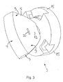
- the first housing part 3 is an optical system 5 for bundling the light emitted by the light-emitting diode 2 Light arranged.
- the optic 5 is a light guide with a light entrance surface 6 and formed of a light-emitting surface 7 spaced therefrom.
- the light entrance surface 6 is a light exit window 8 of the light emitting diode 2 and the light exit surface 7 of the lens facing.
- Between the light entry surface 6 and the light exit surface 7 is the coupled through the light entrance surface 7 in optics 5 light of the LED 2 below Utilization of the total reflection the side boundary surfaces 9 of the optics 5 in this guided.
- the optic 5 is designed such that in the emission region of the light exit surface 7 a provided for the light emitting diode 2 associated lighting function Light distribution is achieved.
- the second housing part 4 of the holding device 1 is as a solid cooling element of a formed metallic material. Between the first housing part 3 and the second Housing part 4, the receptacle for the light emitting diode 2 is formed. In Fig. 2 it can be seen that the receptacle in the second housing part 4 has an approximately cylindrical inner cavity has, in which a portion of the light emitting diode 2 is inserted.
- the light-emitting diode 2 has an approximately circular disk-shaped metal core board 10, on which a in the drawing is not shown in detail arranged light-emitting semiconductor chip, which is integrated in a light-emitting diode housing 11.
- a light-emitting diode housing 11 On the light-emitting diode housing 11 is the Light emission window 8 arranged, with its rear side of a Lichtabstrahlstelle 12th the semiconductor chip faces and on its front side a light output surface 13th having.
- From the light-emitting diode housing 11 are laterally electrical connection contacts Led out via bonding wires with power supply terminals of the semiconductor chip are connected.
- the connection contacts 14 are not closer in the drawing Power supply lines shown connected to a drive circuit connected to connected to the battery of the vehicle.
- the light-emitting diode 2 is arranged in the receptacle of the holding device 1 such that they with the semiconductor chip remote from the rear side of the metal core board 11 at the bottom the recording rests flat against the second housing part 4.
- the front of the metal core board lies flat against the semiconductor chip.
- the first housing part 3 designed as a cap part Coupling element 15 has. This is solvable with a matching one Counter-coupling element 16 of the second housing part 4 connectable.
- the coupling element 15 and the counter-coupling element 16 form a bayonet connection.
- the Counter-coupling element 16 has on its outer circumference three coupling projections 17th on, in the locking position in each case an undercut of the coupling element 15 behind. With the aid of a locking element 18, the bayonet connection is in the connecting position locked.
- the locking element 18 as paragraph or Stage is formed, which is arranged on one of the coupling projections 17.
- the coupling element 15 and the optics 5 are formed as an integral with each other injection molded part. It but other embodiments are possible in which the coupling element 15 and the optics 5 produced as separate parts and then in particular by locking, Gluing and / or welding are joined together.
- the light output surface 13 of the light exit window. 8 is convex and extends in a spherical surface concentric with the Lichtabstrahlstelle 12 of the light emitting diode 2 is arranged.
- the light entry surface 6 of the optics 5 concave and to the light output surface 13 of the Light exit window 8 is designed to match.
- the light entry surface 6 and the light output surface 13 form centering bevels, which are transverse to the optical axis 19 of the LED 2 run.
- the receptacle for the light-emitting diode 2 is designed in such a way that that the light output surface 13 positively to the light inlet surface 6 to the plant comes.
- the housing parts 3, 4 abutments, between which the light emitting diode. 2 is arranged.
- the Lichtabstrahlstelle 12 of the light emitting diode. 2 when connecting the housing parts 3, 4 automatically relative to the light entry surface 6 of the Optics 5 centered.
- the holding device 1 thus enables a self-centering of LED 2.
- an optical gel may be arranged, whose optical refractive index approximately corresponds to the refractive index of the light exit window 8 and the optics 5.
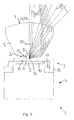
- the optics 5 between the light entry surface 6 and the Light exit surface 7 has an inner cavity 20 which is formed as an air lens.
- the inner cavity 20 At the Passage through the between the material of the optic 5 and the inner cavity 20th formed convex boundary surfaces are light rays 21, which the inner cavity 20 obliquely to the optical axis 19 of the light emitting diode 2 prevail, to the optical axis 19th broken down.
- the inner cavity 20 the optics 5 approximately perpendicular to their plane of the drawing in Fig. 5 corresponding extension plane interspersed.
- the inner cavity 20 is approximately centered to the optical axis 19 of the light emitting diode second in a central region of the light beam emitted by the light-emitting diode 2 arranged.
- the optics 5 also be designed as a lens or reflector can.
Landscapes
- Engineering & Computer Science (AREA)
- General Engineering & Computer Science (AREA)
- Physics & Mathematics (AREA)
- Microelectronics & Electronic Packaging (AREA)
- Optics & Photonics (AREA)
- Non-Portable Lighting Devices Or Systems Thereof (AREA)
- Arrangement Of Elements, Cooling, Sealing, Or The Like Of Lighting Devices (AREA)
- Led Device Packages (AREA)
Abstract
Description
- Fig. 1
- eine Seitenansicht einer ein erstes und ein zweites Gehäuseteil aufweisenden Halteeinrichtung für eine Leuchtdiode einer Fahrzeugleuchte,
- Fig. 2
- eine dreidimensionale Ansicht des zweites Gehäuseteils mit der darin angeordneten Leuchtdiode,
- Fig. 3
- eine Ansicht auf die Vorderseite des ersten Gehäuseteils mit einer daran angeordneten Optik zum Bündeln des von der Leuchtdiode abgestrahlten Lichts,
- Fig. 4
- eine Ansicht auf die der Leuchtdiode zugewandte Innenseite des ersten Gehäuseteils,
- Fig. 5
- einen Längsschnitt durch die in Fig. 1 gezeigte Baugruppe, bestehend aus der Halteeinrichtung und der Leuchtdiode, wobei die Schnittebene der Erstreckungsebene der Optik entspricht, und
- Fig. 6
- einen Längsschnitt durch die in Fig. 1 gezeigte Baugruppe, bestehend aus der Halteeinrichtung und der Leuchtdiode, wobei die Schnittebene rechtwinklig zur Erstreckungsebene der Optik verläuft.
Claims (10)
- Fahrzeugleuchte, mit mindestens einer ein Lichtaustrittsfenster (8) aufweisenden Leuchtdiode (2) als Lichtquelle und mit wenigstens einer mit einer Lichteintrittsfläche (6) dem Lichtaustrittsfenster (8) zugewandten Optik (5) zum Bündeln des von der Leuchtdiode (2) abgestrahlten Lichts sowie mit einer Halteeinrichtung (1) zum Positionieren der Leuchtdiode (2) an der Optik (5), dadurch gekennzeichnet, dass die Halteeinrichtung (1) ein Gehäuse mit einem ersten, die Optik (5) aufweisenden Gehäuseteil (3) und einem damit verbundenen zweiten, als Kühlelement ausgebildeten Gehäuseteil (4) aufweist, dass zwischen diesen Gehäuseteilen (3, 4) eine Aufnahme für die Leuchtdiode (2) gebildet ist, in der die Leuchtdiode (2) derart angeordnet ist, dass sie mit ihrer dem Lichtaustrittsfenster (8) abgewandten Rückseite flächig an dem zweiten Gehäuseteil (4) anliegt, und dass an der Aufnahme und/oder der Leuchtdiode (2) wenigstens ein Zentrierelement vorgesehen ist, zum Zentrieren der Lichteintrittsfläche (6) relativ zu dem Lichtaustrittsfenster (8).
- Fahrzeugleuchte nach Anspruch 1, dadurch gekennzeichnet, dass das wenigstens eine Zentrierelement mindestens eine Zentrierschräge aufweist, die quer zur optischen Achse (19) der Leuchtdiode (2) verläuft.
- Fahrzeugleuchte nach Anspruch 1 oder 2, dadurch gekennzeichnet, dass die Leuchtdiode (2) eine vorzugsweise als Metallkernplatine (10) ausgebildete Trägerplatte hat, auf der ein lichtemittierender Halbleiterchip angeordnet ist, und dass die Trägerplatte mit ihrer dem Halbleiterchip zugewandten Vorderseite flächig an dem Halbleiterchip und mit ihrer Rückseite flächig an dem zweiten Gehäuseteil (4) anliegt.
- Fahrzeugleuchte nach einem der Ansprüche 1 bis 3, dadurch gekennzeichnet, dass das Lichtaustrittsfenster (8) eine konvexe Lichtauskoppelfläche (13) aufweist, die sich vorzugsweise in einer konzentrisch zur Lichtabstrahlstelle (12) der Leuchtdiode (2) angeordneten Kugeloberfläche erstreckt, dass die Lichteintrittsfläche (6) der Optik (5) konkav und zu der Lichtauskoppelfläche (13) passend ausgebildet ist, und dass die Aufnahme für die Leuchtdiode (2) derart ausgebildet ist, dass die Lichtauskoppelfläche (13) formschlüssig an der Lichteintrittsfläche (6) zur Anlage kommt.
- Fahrzeugleuchte nach einem der Ansprüche 1 bis 4, dadurch gekennzeichnet, dass das erste Gehäuseteil (3) der Halteeinrichtung (1) ein lösbar mit dem zweiten Gehäuseteil (4) verbindbares, vorzugsweise als Überwurfteil ausgebildetes Kupplungselement (15) aufweist, und dass dieses Kupplungselement (15) vorzugsweise einstückig mit der Optik (5) ausgebildet ist.
- Fahrzeugleuchte nach einem der Ansprüche 1 bis 5, dadurch gekennzeichnet, dass das erste Gehäuseteil (3) und das zweite Gehäuseteil (4) der Halteeinrichtung (1) lösbar miteinander verbindbar sind, vorzugsweise mittels einer in einer Verbindungsstellung verrasteten Bajonett-Verbindung.
- Fahrzeugleuchte nach einem der Ansprüche 1 bis 6, dadurch gekennzeichnet, dass sie ein Leuchtengehäuse mit einer Innenhöhlung aufweist, das eine Lichtaustrittsöffnung aufweist, die durch eine Lichtscheibe abgedeckt ist, und dass in der Innenhöhlung mindestens eine Fassung zur Aufnahme der Halteeinrichtung (1) angeordnet ist.
- Fahrzeugleuchte nach einem der Ansprüche 1 bis 7, dadurch gekennzeichnet, dass das zweite Gehäuseteil (4) der Halteeinrichtung (1) einstückig mit dem Leuchtengehäuse ausgebildet ist.
- Fahrzeugleuchte nach einem der Ansprüche 1 bis 8, dadurch gekennzeichnet, dass zwischen dem Lichtaustrittsfenster (8) der Leuchtdiode (2) und der Lichteintrittsfläche (7) der Optik (5) ein Optik-Gel angeordnet ist, dessen optischer Brechungsindex etwa dem Brechungsindex des Lichtaustrittsfensters (8) und der Optik (5) entspricht.
- Fahrzeugleuchte nach einem der Ansprüche 1 bis 9, dadurch gekennzeichnet, dass die Optik (5) als Lichtleitkörper ausgebildet ist, in dem das durch die Lichteintrittsfläche (6) eingekoppelte Licht der Leuchtdiode (2) unter Ausnutzung der Totalreflexion an den Grenzflächen des Lichtleitkörpers geführt wird.
Applications Claiming Priority (2)
| Application Number | Priority Date | Filing Date | Title |
|---|---|---|---|
| DE10343840 | 2003-09-23 | ||
| DE10343840A DE10343840A1 (de) | 2003-09-23 | 2003-09-23 | Fahrzeugleuchte |
Publications (2)
| Publication Number | Publication Date |
|---|---|
| EP1519107A1 true EP1519107A1 (de) | 2005-03-30 |
| EP1519107B1 EP1519107B1 (de) | 2006-09-13 |
Family
ID=34177882
Family Applications (1)
| Application Number | Title | Priority Date | Filing Date |
|---|---|---|---|
| EP04022491A Expired - Lifetime EP1519107B1 (de) | 2003-09-23 | 2004-09-22 | Fahrzeugleuchte |
Country Status (3)
| Country | Link |
|---|---|
| EP (1) | EP1519107B1 (de) |
| DE (2) | DE10343840A1 (de) |
| ES (1) | ES2273139T3 (de) |
Cited By (7)
| Publication number | Priority date | Publication date | Assignee | Title |
|---|---|---|---|---|
| WO2006097067A1 (de) * | 2005-03-16 | 2006-09-21 | Osram Opto Semiconductors Gmbh | Licht emittierendes modul mit led und passstiften für die montage eines optischen elements |
| FR2906009A1 (fr) * | 2006-09-19 | 2008-03-21 | Valeo Vision Sa | Dispositif d'eclairage et/ou de signalisation pour vehicule automobile. |
| WO2010006971A1 (de) * | 2008-07-16 | 2010-01-21 | Osram Gesellschaft mit beschränkter Haftung | Halterungsrahmen mit mindestens einem optischen element |
| WO2013079302A1 (en) * | 2011-11-29 | 2013-06-06 | Osram Gmbh | Led light source assembly for automotive forward lighting apparatus |
| EP3062013A1 (de) * | 2015-02-26 | 2016-08-31 | T.Y.C. Brother Industrial Co., Ltd. | Fahrzeuglampe |
| CN106152009A (zh) * | 2015-04-15 | 2016-11-23 | 堤维西交通工业股份有限公司 | 车灯 |
| DE102019106221A1 (de) * | 2019-03-12 | 2020-09-17 | HELLA GmbH & Co. KGaA | Beleuchtungsvorrichtung für Fahrzeuge |
Families Citing this family (7)
| Publication number | Priority date | Publication date | Assignee | Title |
|---|---|---|---|---|
| DE102005044447B4 (de) * | 2005-09-09 | 2014-07-17 | SMR Patents S.à.r.l. | Leuchte für Außenrückspiegel von Fahrzeugen, vorzugsweise von Kraftfahrzeugen |
| JP4616200B2 (ja) * | 2006-03-22 | 2011-01-19 | 本田技研工業株式会社 | 車両用灯火器 |
| AT502490B1 (de) | 2006-04-27 | 2007-04-15 | Zizala Lichtsysteme Gmbh | Lichtleitelement |
| DE102008055864A1 (de) * | 2008-11-05 | 2010-05-06 | Zumtobel Lighting Gmbh | LED-Leuchte |
| DE102009039577B4 (de) | 2009-09-01 | 2021-09-30 | Automotive Lighting Reutlingen Gmbh | Lichtmodul für eine Beleuchtungseinrichtung eines Kraftfahrzeugs |
| DE102010013783B4 (de) * | 2010-04-03 | 2013-11-21 | Festool Group Gmbh & Co. Kg | Beleuchtungsvorrichtung mit LEDs |
| DE102011006643A1 (de) * | 2011-04-01 | 2012-10-04 | Osram Ag | Optisches Element und Leuchtvorrichtung |
Citations (4)
| Publication number | Priority date | Publication date | Assignee | Title |
|---|---|---|---|---|
| DE19507234A1 (de) * | 1995-03-02 | 1996-09-05 | Fer Fahrzeugelektrik Gmbh | Fahrzeugsignalleuchte mit mehreren Leuchtdioden |
| EP1176359A2 (de) * | 2000-07-29 | 2002-01-30 | Hella KG Hueck & Co. | Leuchte für Fahrzeuge |
| EP1298382A1 (de) * | 2001-09-28 | 2003-04-02 | Osram-Sylvania Inc. | Austauschbare LED-Lampenbirne mit auswechselbarer Linsenoptik |
| WO2003048637A1 (en) * | 2001-12-06 | 2003-06-12 | Fraen Corporation S.R.L. | High-heat-dissipation lighting module |
Family Cites Families (4)
| Publication number | Priority date | Publication date | Assignee | Title |
|---|---|---|---|---|
| BR9811170A (pt) * | 1997-08-12 | 2000-07-25 | Decoma Int Inc | Conjunto de lente bi-reflexiva e conjunto emissor de luz para utilização em um veìculo |
| DE19926561A1 (de) * | 1999-06-11 | 2000-12-14 | Diehl Stiftung & Co | Strahler, insbesondere Leseleuchte in Kabinen von Fahrzeugen |
| DE10110835B4 (de) * | 2001-03-06 | 2005-02-17 | Osram Opto Semiconductors Gmbh | Beleuchtungsanordnung mit einer Mehrzahl von LED-Modulen auf einer Kühlkörperoberfläche |
| DE20219483U1 (de) * | 2002-12-16 | 2003-05-08 | FER Fahrzeugelektrik GmbH, 99817 Eisenach | Fahrzeugleuchte |
-
2003
- 2003-09-23 DE DE10343840A patent/DE10343840A1/de not_active Withdrawn
-
2004
- 2004-09-22 ES ES04022491T patent/ES2273139T3/es not_active Expired - Lifetime
- 2004-09-22 DE DE502004001459T patent/DE502004001459D1/de not_active Expired - Lifetime
- 2004-09-22 EP EP04022491A patent/EP1519107B1/de not_active Expired - Lifetime
Patent Citations (4)
| Publication number | Priority date | Publication date | Assignee | Title |
|---|---|---|---|---|
| DE19507234A1 (de) * | 1995-03-02 | 1996-09-05 | Fer Fahrzeugelektrik Gmbh | Fahrzeugsignalleuchte mit mehreren Leuchtdioden |
| EP1176359A2 (de) * | 2000-07-29 | 2002-01-30 | Hella KG Hueck & Co. | Leuchte für Fahrzeuge |
| EP1298382A1 (de) * | 2001-09-28 | 2003-04-02 | Osram-Sylvania Inc. | Austauschbare LED-Lampenbirne mit auswechselbarer Linsenoptik |
| WO2003048637A1 (en) * | 2001-12-06 | 2003-06-12 | Fraen Corporation S.R.L. | High-heat-dissipation lighting module |
Cited By (11)
| Publication number | Priority date | Publication date | Assignee | Title |
|---|---|---|---|---|
| WO2006097067A1 (de) * | 2005-03-16 | 2006-09-21 | Osram Opto Semiconductors Gmbh | Licht emittierendes modul mit led und passstiften für die montage eines optischen elements |
| US7621658B2 (en) | 2005-03-16 | 2009-11-24 | Osram Opto Semiconductors Gmbh | Light-emitting module |
| FR2906009A1 (fr) * | 2006-09-19 | 2008-03-21 | Valeo Vision Sa | Dispositif d'eclairage et/ou de signalisation pour vehicule automobile. |
| WO2010006971A1 (de) * | 2008-07-16 | 2010-01-21 | Osram Gesellschaft mit beschränkter Haftung | Halterungsrahmen mit mindestens einem optischen element |
| CN102099620A (zh) * | 2008-07-16 | 2011-06-15 | 奥斯兰姆有限公司 | 具有至少一个光学元件的保持框架 |
| WO2013079302A1 (en) * | 2011-11-29 | 2013-06-06 | Osram Gmbh | Led light source assembly for automotive forward lighting apparatus |
| EP3062013A1 (de) * | 2015-02-26 | 2016-08-31 | T.Y.C. Brother Industrial Co., Ltd. | Fahrzeuglampe |
| TWI582335B (zh) * | 2015-02-26 | 2017-05-11 | 堤維西交通工業股份有限公司 | Lights |
| CN106152009A (zh) * | 2015-04-15 | 2016-11-23 | 堤维西交通工业股份有限公司 | 车灯 |
| DE102019106221A1 (de) * | 2019-03-12 | 2020-09-17 | HELLA GmbH & Co. KGaA | Beleuchtungsvorrichtung für Fahrzeuge |
| DE102019106221B4 (de) | 2019-03-12 | 2026-05-21 | HELLA GmbH & Co. KGaA | Beleuchtungsvorrichtung für Fahrzeuge |
Also Published As
| Publication number | Publication date |
|---|---|
| DE10343840A1 (de) | 2005-04-28 |
| DE502004001459D1 (de) | 2006-10-26 |
| EP1519107B1 (de) | 2006-09-13 |
| ES2273139T3 (es) | 2007-05-01 |
Similar Documents
| Publication | Publication Date | Title |
|---|---|---|
| EP1519107B1 (de) | Fahrzeugleuchte | |
| EP2317213B1 (de) | Leuchtdiodenmodul einer Kraftfahrzeugbeleuchtungseinrichtung und Kraftfahrzeugbeleuchtungseinrichtung | |
| EP1859196B1 (de) | Licht emittierendes modul mit led und passstiften für die montage eines optischen elements | |
| EP1805815B1 (de) | Beleuchtungseinrichtung, kfz-scheinwerfer und verfahren zur herstellung einer beleuctungseinrichtung | |
| EP3021041B1 (de) | Lichtquellenmodul für einen fahrzeugscheinwerfer | |
| DE102008061431B4 (de) | Fahrzeugleuchte | |
| DE10250383B4 (de) | Leuchtdiodenanordnung mit Reflektor | |
| DE102012223854A1 (de) | Remote-Phosphor-Konvertereinrichtung | |
| WO2002054129A1 (de) | Kopplungsanordnung zum optischen koppeln eines lichtwellenleiters mit einem elektro-optischen element | |
| DE102007050924B4 (de) | LED-bestückter Leuchtenmodul, insbesondere für Kraftfahrzeuge | |
| WO2013127632A1 (de) | Beleuchtungseinrichtung | |
| EP2270384A2 (de) | Lampe | |
| EP1828671A1 (de) | Beleuchtungseinrichtung mit mindestens einer leuchtdiode und fahrzeugscheinwerfer | |
| DE102005020908A1 (de) | Beleuchtungsvorrichtung | |
| EP2095016A1 (de) | Beleuchtungseinheit für fahrzeugscheinwerfer und fahrzeugscheinwerfer | |
| DE102008033416A1 (de) | Halterungsrahmen | |
| DE102015216662A1 (de) | Leuchtmittel mit LEDs | |
| DE202014001375U1 (de) | Beleuchtungseinrichtung | |
| DE10129950A1 (de) | Leuchte für Fahrzeuge und Verfahren zur Herstellung derselben | |
| DE102022108281B4 (de) | Lichtmodul und Kraftfahrzeugbeleuchtungseinrichtung mit einem solchen Lichtmodul | |
| EP1522459A2 (de) | Innenleuchte für Fahrzeuge | |
| DE29910417U1 (de) | Reflektorleuchte | |
| WO2009067985A1 (de) | Anordnung mit einem licht emittierendem modul und einem flexiblen leitungsträger | |
| DE10259236A1 (de) | Innenleuchte für Fahrzeuge | |
| WO2018054652A2 (de) | Beleuchtungsvorrichtung |
Legal Events
| Date | Code | Title | Description |
|---|---|---|---|
| PUAI | Public reference made under article 153(3) epc to a published international application that has entered the european phase |
Free format text: ORIGINAL CODE: 0009012 |
|
| AK | Designated contracting states |
Kind code of ref document: A1 Designated state(s): AT BE BG CH CY CZ DE DK EE ES FI FR GB GR HU IE IT LI LU MC NL PL PT RO SE SI SK TR |
|
| AX | Request for extension of the european patent |
Extension state: AL HR LT LV MK |
|
| 17P | Request for examination filed |
Effective date: 20050928 |
|
| AKX | Designation fees paid |
Designated state(s): DE ES FR IT |
|
| GRAP | Despatch of communication of intention to grant a patent |
Free format text: ORIGINAL CODE: EPIDOSNIGR1 |
|
| RIN1 | Information on inventor provided before grant (corrected) |
Inventor name: NEUMANN, CORNELIUS, DR. Inventor name: SACHS-DUECKER, GABRIELE MONIKA Inventor name: PRENGER, PETER |
|
| GRAS | Grant fee paid |
Free format text: ORIGINAL CODE: EPIDOSNIGR3 |
|
| GRAA | (expected) grant |
Free format text: ORIGINAL CODE: 0009210 |
|
| AK | Designated contracting states |
Kind code of ref document: B1 Designated state(s): DE ES FR IT |
|
| REF | Corresponds to: |
Ref document number: 502004001459 Country of ref document: DE Date of ref document: 20061026 Kind code of ref document: P |
|
| ET | Fr: translation filed | ||
| REG | Reference to a national code |
Ref country code: ES Ref legal event code: FG2A Ref document number: 2273139 Country of ref document: ES Kind code of ref document: T3 |
|
| PLBE | No opposition filed within time limit |
Free format text: ORIGINAL CODE: 0009261 |
|
| STAA | Information on the status of an ep patent application or granted ep patent |
Free format text: STATUS: NO OPPOSITION FILED WITHIN TIME LIMIT |
|
| 26N | No opposition filed |
Effective date: 20070614 |
|
| PGFP | Annual fee paid to national office [announced via postgrant information from national office to epo] |
Ref country code: ES Payment date: 20071024 Year of fee payment: 4 |
|
| REG | Reference to a national code |
Ref country code: ES Ref legal event code: FD2A Effective date: 20080923 |
|
| PG25 | Lapsed in a contracting state [announced via postgrant information from national office to epo] |
Ref country code: ES Free format text: LAPSE BECAUSE OF NON-PAYMENT OF DUE FEES Effective date: 20080923 |
|
| PGFP | Annual fee paid to national office [announced via postgrant information from national office to epo] |
Ref country code: DE Payment date: 20100915 Year of fee payment: 7 |
|
| PGFP | Annual fee paid to national office [announced via postgrant information from national office to epo] |
Ref country code: FR Payment date: 20110922 Year of fee payment: 8 |
|
| PGFP | Annual fee paid to national office [announced via postgrant information from national office to epo] |
Ref country code: IT Payment date: 20110921 Year of fee payment: 8 |
|
| REG | Reference to a national code |
Ref country code: FR Ref legal event code: ST Effective date: 20130531 |
|
| PG25 | Lapsed in a contracting state [announced via postgrant information from national office to epo] |
Ref country code: DE Free format text: LAPSE BECAUSE OF NON-PAYMENT OF DUE FEES Effective date: 20130403 |
|
| PG25 | Lapsed in a contracting state [announced via postgrant information from national office to epo] |
Ref country code: IT Free format text: LAPSE BECAUSE OF NON-PAYMENT OF DUE FEES Effective date: 20120922 Ref country code: FR Free format text: LAPSE BECAUSE OF NON-PAYMENT OF DUE FEES Effective date: 20121001 |
|
| REG | Reference to a national code |
Ref country code: DE Ref legal event code: R119 Ref document number: 502004001459 Country of ref document: DE Effective date: 20130403 |