EP1518969B1 - Bouche d'égout - Google Patents
Bouche d'égout Download PDFInfo
- Publication number
- EP1518969B1 EP1518969B1 EP04019574A EP04019574A EP1518969B1 EP 1518969 B1 EP1518969 B1 EP 1518969B1 EP 04019574 A EP04019574 A EP 04019574A EP 04019574 A EP04019574 A EP 04019574A EP 1518969 B1 EP1518969 B1 EP 1518969B1
- Authority
- EP
- European Patent Office
- Prior art keywords
- drain
- stub
- bowl
- pipe
- stand
- Prior art date
- Legal status (The legal status is an assumption and is not a legal conclusion. Google has not performed a legal analysis and makes no representation as to the accuracy of the status listed.)
- Expired - Lifetime
Links
- 238000009434 installation Methods 0.000 description 24
- XLYOFNOQVPJJNP-UHFFFAOYSA-N water Substances O XLYOFNOQVPJJNP-UHFFFAOYSA-N 0.000 description 14
- 238000004140 cleaning Methods 0.000 description 2
- 230000000694 effects Effects 0.000 description 2
- 230000000149 penetrating effect Effects 0.000 description 2
- 230000006978 adaptation Effects 0.000 description 1
- 230000001419 dependent effect Effects 0.000 description 1
- 230000003670 easy-to-clean Effects 0.000 description 1
- 238000004519 manufacturing process Methods 0.000 description 1
- 238000012856 packing Methods 0.000 description 1
- 238000005192 partition Methods 0.000 description 1
- 238000007789 sealing Methods 0.000 description 1
- 238000000638 solvent extraction Methods 0.000 description 1
- 239000002699 waste material Substances 0.000 description 1
Images


Classifications
-
- E—FIXED CONSTRUCTIONS
- E03—WATER SUPPLY; SEWERAGE
- E03F—SEWERS; CESSPOOLS
- E03F5/00—Sewerage structures
- E03F5/04—Gullies inlets, road sinks, floor drains with or without odour seals or sediment traps
- E03F5/0407—Floor drains for indoor use
-
- E—FIXED CONSTRUCTIONS
- E03—WATER SUPPLY; SEWERAGE
- E03F—SEWERS; CESSPOOLS
- E03F5/00—Sewerage structures
- E03F5/04—Gullies inlets, road sinks, floor drains with or without odour seals or sediment traps
- E03F2005/0412—Gullies inlets, road sinks, floor drains with or without odour seals or sediment traps with means for adjusting their position with respect to the surrounding surface
- E03F2005/0413—Gullies inlets, road sinks, floor drains with or without odour seals or sediment traps with means for adjusting their position with respect to the surrounding surface for height adjustment
-
- E—FIXED CONSTRUCTIONS
- E03—WATER SUPPLY; SEWERAGE
- E03F—SEWERS; CESSPOOLS
- E03F5/00—Sewerage structures
- E03F5/04—Gullies inlets, road sinks, floor drains with or without odour seals or sediment traps
- E03F2005/0412—Gullies inlets, road sinks, floor drains with or without odour seals or sediment traps with means for adjusting their position with respect to the surrounding surface
- E03F2005/0414—Gullies inlets, road sinks, floor drains with or without odour seals or sediment traps with means for adjusting their position with respect to the surrounding surface for inclination adjustment
-
- E—FIXED CONSTRUCTIONS
- E03—WATER SUPPLY; SEWERAGE
- E03F—SEWERS; CESSPOOLS
- E03F5/00—Sewerage structures
- E03F5/04—Gullies inlets, road sinks, floor drains with or without odour seals or sediment traps
- E03F2005/0416—Gullies inlets, road sinks, floor drains with or without odour seals or sediment traps with an odour seal
- E03F2005/0418—Gullies inlets, road sinks, floor drains with or without odour seals or sediment traps with an odour seal in the form of a bell siphon
Definitions
- the present invention concerns a drain system including a grate element, a bell part, a funnel part, a drain bowl, a stand-pipe and a drain stub, where an upper part of the bell part is secured to the grate element for forming a dismountable lid which is adapted for fastening to the upper part of the funnel part that is downwards connected to the drain bowl in which the stand-pipe is disposed so that it extends from a bottom of the said drain bowl and up into the bell part, and where stand-pipe downwards includes a connection sleeve for the drain stub, wherein the bottom of the drain bowl is shaped inclining at least over a sub-distance, and the drain stub is angle-bent
- drain units with low installation height e.g. by making the drain units smaller and/or with a drain bowl with a side outlet.
- FR-A-1 550 526 An example of a drain system described in the introductory paragraph is known from FR-A-1 550 526 .
- This document discloses a system which is inclining over the bottom around the drain stub without any part of the bottom being flat. Moreover the drain stub has no varying cross-section. Therefore the system does not have flat bottom part it may be used for abutting on a side narrowing of the drain stub.
- prior art drain units are not made flexible, as the drain stub is typically fixed and oriented at a certain direction in relation to the grate element of the drain unit. This may entail difficult mounting of the drain unit in e.g. existing wet room installations, as the existing pipe systems either do not fit the drain stub of the drain unit or are oriented in an inappropriate direction in relation to the grate element of the drain system, causing extra work with adapting pipe system and installation opening.
- prior art drain units exist, with a stand-pipe that includes a sleeve, whereby the mounting of the drain unit is effected in that the drain bowl is disposed and pressed down over a drain stub.
- drain stub is permanently mounted and thus not very flexible. This implies that it may be difficult to adapt the drain unit to existing installations, since the sleeve connection between drain stub and stand-pipe only allows a vertical movement and not a horizontal movement.
- the installation worker is required to carry different types of fittings, as e.g. connecting pieces, sockets, pipe sections and pipe bends with different dimensions.
- the maker can decide to produce an assortment of fittings and to deliver these with each drain unit, implying increased production cost and waste of resources since each time there will be some fittings in excess.
- the purpose of the present invention is thus to indicate a drain unit which is made of few parts and which has a low installation height, simultaneously with the mounting of the drain unit is easy and rapid.
- the drain unit In order to prevent air and return flow in the drain system, the drain unit is designed with a water trap whereby the drain water collected in the drain bowl passes down by the bell part and up between the stand-pipe and the bell part, after which the drain water may leave the drain system via stand-pipe and drain stub.
- the bell part is fastened to a grate element so that they together form a dismountable lid which, e.g. by means of screws, can be removed from the funnel part of the drain unit.
- the drain unit is provided with a dismountable part, e.g. it is possible to remove the dismountable lid and thereby access the stand-pipe and parts of the drain stub. This provides that it is easy to clean the drain unit itself while at the same time it is possible to flush pipe/sewer system, or to use a cleaning wire from the drain side, in case of clogging in some part of the succeeding pipe/sewer system.
- the grate element is typically a circular or polygonal plate in which is provided a number of openings which may be arranged symmetrically or in certain patterns. The important thing is that there are enough openings, or that the openings are large enough, to allow the amount of drain water appearing to be collected/led down into the drain bowl.
- the grate element may have a slight concave or convex shape, where the concave shape may contribute to prevent large elements in the drain water from penetrating down into the drain bowl, while the convex shape may contribute to leading the drain water down into the drain bowl.
- the connecting end of the drain stub is inserted in the stand-pipe, which in the lower end includes a connection sleeve in which is disposed a sealing ring that ensure a tight connection between stand-pipe and drain stub.
- the drain stub is angle-bent and with varying cross-section.
- the flexibility of the drain unit is achieved in that the drain stub is angle-bent and with varying cross-section.
- the installation worker may cut in the part of the drain stub with varying cross-section so that the drain stub has appropriate length and cross-sectional dimension that fit the succeeding connection in the pipe/sewer system.
- the bottom of the drain bowl is shaped inclining over a sub-distance. This entails that the bottom in the area on the angle-bent drain stub, which has a varying cross-section, can be adapted, whereby the total installation height of the drain system becomes less than if the drain unit had a flat bottom and a vertically downwards directed drain stub with an angled bend thereon.
- the reduction in the installation height may be up to half the cross-sectional dimension of the drain stub, e.g. if the drain stub has diameter 40 around the angle-bent part of the drain stub, the succeeding varying cross-section of the drain stub will be reduced so that the installation height of the total drain unit will be equal to the height of the drain bowl plus about 20 mm from the drain stub.
- the said inclining sub-distance extends between mutually parallel sub-surfaces of the bottom.
- the inclining sub-distance will be the part of the bottom of the drain bowl that includes the area in which the stand-pipe is placed.
- the drain bowl has sub-surfaces in two parallel areas along each side edge of the bottom bowl.
- a flat bottom part it may be used for abutting on the side narrowing of the drain stub. This means that when the bottom face is abutting on the side narrowing of the drain stub, the drain bowl will be disposed supported in a stable way.
- the flat bottom parts may be used for blocking-up, e.g. in situations where the mounting opening is too deep or uneven for stable mounting of the drain unit, e.g. by using a wedge a support of the drain bowl of the drain unit in the desired position may be provided.
- the stand-pipe in the drain bowl is typically disposed centrally so that it is possible to mount the drain stub projecting at any angle relative to the drain bowl, while at the same time the drain water may flow uniformly around the bell part, irrespectively of the direction in which the drain water passes the grate element.
- the entire bottom of the drain bowl is shaped inclining so that the drain bowl does not have one or more mainly horizontal bottom parts.
- An advantage of this embodiment of the invention is that the drain system may be adjusted in height in relation to the surrounding floor surface by rotating the drain bowl around the centre axis of the stand-pipe, whereby the inclining bottom of the drain bowl will contact the top side of the drain stub, where rotation of the drain bowl will either move the drain bowl and the grate element upwards or downwards until the grate element fits the level of the surrounding floor surface.
- a drain stub which is designed with a connecting end for inserting in the connecting sleeve and close thereby a side narrowing, and that the varying cross-section is found opposite to the connecting end.
- the side narrowing of the drain stub which is close at the connecting end, entails that the preferably flat bottom part of the drain bowl corresponds in shape with the side narrowing, whereby these two elements engage each other, whereby the bottom part bear on the top side of the side narrowing and not on the top side of the other varying cross-sections of the drain stub, providing that the installation height is substantially reduced
- the drain stub will be shaped with varying cross-section. This entails that during mounting, the installation worker may place the drain unit so that the grate element by rotation of drain stub and/or drain bowl can be adapted to the desired position in relation to the surrounding floor surface and may cut off the drain stub subsequently in the said varying cross-sections so that the drain stub has a length and cross-section that fit the succeeding course of the pipe/sewer system.
- the dimensions of the said connecting end and a section after the side narrowing are identical. This means that the installation worker can cut off the drain stub in/or around the section after the side narrowing, and then choose which part of the drain stub that is to be mounted in the connection sleeve of the stand-pipe
- a horizontal adjusting possibility of the drain bowl of the drain unit would be desirable when the drain unit is placed in e.g. existing installations in old buildings, and therefore the said varying cross-section is laterally displaced, as they have a common sidewall.
- the said varying cross-sections may be provided coaxially, providing the advantage that the drain stub can be mounted for different types of cross-sectional dimensions of the succeeding pipe/sewer system.
- Figs. 1 and 2 shows a drain unit 1 that includes a grate element 2 which is shown here mounted to a funnel part 4 with corner screws 20.
- the funnel part 4 continues in a drain bowl 5, where under drain bowl 5 there is fitted a drain stub 7.
- bottom part 9 of drain bowl 5 is disposed down into side narrowing 12 of drain stub 7.
- Fig. 3 shows a section in drain unit 1, where it appears that grate element 2 is mounted on bell part 3 which forms a dismountable lid 8 that is fastened to a funnel part 4 continuing into drain bowl 5 where a centred stand-pipe 6 is disposed.
- Drain stub 7 is mounted in the connecting sleeve 10 which is disposed internally and in the lower part of stand-pipe 6 so that it ensures that drain unit 1 is not leaking to the surroundings.
- drain stub 7 corresponds in shape with a part of drain bowl 5 and stand-pipe 6, and thereby it is possible to rotate drain stub 7 360 degrees so that drain unit 1 can be adjusted laterally and in height.
- drain stub 7 is mounted in centrally disposed stand-pipe 6 of drain bowl 5 by inserting the connecting end into connecting sleeve 10 which is provided with a packing unit 21 that prevents water from penetrating to the exterior of the drain unit 1.
- Drain stub 7 is here shown in the preferred embodiment of the invention, where the drain stub 7 is provided with an angle bend 7a, a narrowing 12 and varying cross-sections 7b and 7c.
- drain stub 7 is shown in a situation of use where the installation worker has cut off an end part 7c of drain stub 7.
- drain unit 1 in the shown embodiment may be mounted with drain stub 7 having an end part 7b with the same cross-sectional diameter as connecting end of drain stub 7.
- the bottom 9 of the drain bowl 5 is designed with varying level, entailing that when drain bowl 5 is rotated about the centre line of the connecting end of the drain stub 7, the drain bowl 5 may be adjusted in height.
- Fig. 6 is shown another possibility, where the installation worker, instead of cutting off the end part 7c of drain stub 7, is cutting off angle bend 7a and the narrowed part 12, so that the part used by the drain stub are the parts 7b and 7c. It is to be noted that parts 7b and 7c of drain stub 7 are having a common sidewall 13 which is laterally offset.
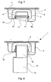
- Fig. 7 On Fig. 7 is shown a sectional view of drain bowl 5 where it is seen that bottom 9 over a sub-distance 11 is formed inclining, and that this inclining sub-distance 11 extends between parallel sub-surfaces 9a and 9b of the bottom 9.
- Fig. 8 On Fig. 8 is shown how the part of drain stub 7, which was shown on Fig. 6, is used for mounting in a drain bowl 5 which was shown on Fig. 7.
- Part 7b of drain stub 7 is mounted in the connecting sleeve 10 of the stand-pipe 6.
- the sections 7b and 7c being laterally offset and having a sidewall 13 in common, it is possible by rotating the drain stub 7 about the centre line of the stand-pipe 6 to cause an eccentric movement of the connecting end of the drain stub 7 to the succeeding pipe/sewer system, or by rotating the drain stub 7 about the centre line of the lower connecting end of the drain stub 7 to cause an eccentric movement of the drain bowl.
Landscapes
- Health & Medical Sciences (AREA)
- Life Sciences & Earth Sciences (AREA)
- Engineering & Computer Science (AREA)
- Hydrology & Water Resources (AREA)
- Public Health (AREA)
- Water Supply & Treatment (AREA)
- Sink And Installation For Waste Water (AREA)
- Electrical Discharge Machining, Electrochemical Machining, And Combined Machining (AREA)
- Centrifugal Separators (AREA)
- Cyclones (AREA)
- Temperature-Responsive Valves (AREA)
- Separation By Low-Temperature Treatments (AREA)
- Transition And Organic Metals Composition Catalysts For Addition Polymerization (AREA)
Claims (4)
- Bouche d'égout (1) comprenant un élément formant grille (2), une partie formant tulipe (3), une partie formant entonnoir (4), une coupe d'évacuation (5), une conduite verticale (6) et un tronçon d'évacuation (7), dans laquelle une partie supérieure de la partie formant tulipe (3) est fixée sur l'élément formant grille (2) pour former un couvercle (8) démontable qui est adapté à être fixé sur la partie supérieure de la partie formant entonnoir (4) qui est raccordée, en direction du bas, à la coupe d'évacuation (5), dans laquelle la conduite verticale (6) est disposée de telle sorte qu'elle s'étend depuis un fond (9) de la coupe d'évacuation (5) pour monter dans la partie formant tulipe (3), et dans laquelle la conduite verticale (6) comprend, en direction du bas, un manchon de liaison (10) destiné au tronçon d'évacuation (7), le fond (9) de la coupe d'évacuation (5) présentant une forme inclinée sur au moins une sous-distance (11) et le tronçon d'évacuation (7) étant coudé selon un angle (7a), caractérisée en ce que a sous-distance (11) inclinée s'étend entre des sous-surfaces (9a, 9b) plates, parallèles les unes aux autres, du fond (9) et en ce que le tronçon d'évacuation (7) présente une section transversale (7b, 7c) variable.
- Bouche d'égout (1) selon la revendication 1, caractérisée en ce que le tronçon d'évacuation (7) présente une extrémité de liaison (7a) destiné à l'insertion dans le manchon de liaison (10) et, à proximité, un rétrécissement latéral (12), et en ce que la section transversale (7b, 7c) variable se trouve à l'opposé de l'extrémité de liaison (7a).
- Bouche d'égout (1) selon la revendication 2, caractérisée en ce que l'extrémité de liaison (7a) et une section (7b) située en aval du rétrécissement latéral (12) présentent les mêmes dimensions.
- Bouche d'égout (1) selon les revendications 1-3, caractérisée en ce que les sections transversales (7b, 7c) variables sont décalées latéralement, à l'endroit où elles ont une paroi latérale (13) en commun.
Applications Claiming Priority (2)
| Application Number | Priority Date | Filing Date | Title |
|---|---|---|---|
| DK200301397 | 2003-09-26 | ||
| DK200301397A DK176029B1 (da) | 2003-09-26 | 2003-09-26 | Aflöbssystem |
Publications (2)
| Publication Number | Publication Date |
|---|---|
| EP1518969A1 EP1518969A1 (fr) | 2005-03-30 |
| EP1518969B1 true EP1518969B1 (fr) | 2007-07-11 |
Family
ID=34178334
Family Applications (1)
| Application Number | Title | Priority Date | Filing Date |
|---|---|---|---|
| EP04019574A Expired - Lifetime EP1518969B1 (fr) | 2003-09-26 | 2004-08-18 | Bouche d'égout |
Country Status (6)
| Country | Link |
|---|---|
| EP (1) | EP1518969B1 (fr) |
| AT (1) | ATE366848T1 (fr) |
| DE (1) | DE602004007445T2 (fr) |
| DK (2) | DK176029B1 (fr) |
| ES (1) | ES2290596T3 (fr) |
| NO (1) | NO337155B1 (fr) |
Families Citing this family (9)
| Publication number | Priority date | Publication date | Assignee | Title |
|---|---|---|---|---|
| ES2387412T3 (es) * | 2007-05-04 | 2012-09-21 | Dlp Limited | Sistema de desagüe de ducha con un dispositivo de conducto de residuos plano |
| EP2142715B1 (fr) * | 2007-05-04 | 2010-12-22 | DLP Limited | Dispositif compact de bonde de vidage pour douche |
| ES2381807T3 (es) * | 2009-05-28 | 2012-05-31 | Franz Kaldewei Gmbh & Co.Kg | Desagüe, especialmente para dispositivos sanitarios |
| DE202011050359U1 (de) * | 2011-06-06 | 2011-10-20 | Aco Severin Ahlmann Gmbh & Co. Kg | Glockengeruchsverschluss |
| FR2981672B1 (fr) * | 2011-10-25 | 2015-09-04 | Allia | Receveur de douche a siphon integre |
| NL2008986C2 (nl) * | 2012-06-12 | 2013-12-16 | Easy Sanitairy Solutions Bv | Afvoerput met sifon. |
| NL2011953C2 (nl) * | 2013-12-12 | 2015-06-15 | Easy Sanitary Solutions B V | Afvoerput met sifon. |
| GB2530786B (en) * | 2014-10-02 | 2018-10-03 | Kohler Mira Ltd | Waste trap |
| CN112127460B (zh) * | 2020-09-27 | 2021-12-10 | 凤阳县和裕市政园林工程有限公司 | 一种适应不同水位的下水道防堵塞装置 |
Family Cites Families (6)
| Publication number | Priority date | Publication date | Assignee | Title |
|---|---|---|---|---|
| CH272194A (de) * | 1949-04-30 | 1950-12-15 | Von Roll Ag | Bodenwasserablauf. |
| DE842779C (de) * | 1949-09-07 | 1952-06-30 | Dominia As | Geruchverschluss fuer Abflussinstallationen |
| FR1550526A (fr) * | 1967-12-12 | 1968-12-20 | ||
| US3593347A (en) * | 1969-08-25 | 1971-07-20 | P I Nemiroff Corp The | Bathtub renovating adaptor apparatus and method |
| US3651826A (en) * | 1969-11-19 | 1972-03-28 | Noriatsu Kojima | Drain trap for horizontal drain pipe |
| JPH1018382A (ja) * | 1996-06-28 | 1998-01-20 | Hokusatsu Home:Kk | 排水管用臭気止め装置 |
-
2003
- 2003-09-26 DK DK200301397A patent/DK176029B1/da not_active IP Right Cessation
-
2004
- 2004-07-02 NO NO20042788A patent/NO337155B1/no not_active IP Right Cessation
- 2004-08-18 AT AT04019574T patent/ATE366848T1/de not_active IP Right Cessation
- 2004-08-18 DE DE602004007445T patent/DE602004007445T2/de not_active Expired - Lifetime
- 2004-08-18 EP EP04019574A patent/EP1518969B1/fr not_active Expired - Lifetime
- 2004-08-18 ES ES04019574T patent/ES2290596T3/es not_active Expired - Lifetime
- 2004-08-18 DK DK04019574T patent/DK1518969T3/da active
Also Published As
| Publication number | Publication date |
|---|---|
| DE602004007445T2 (de) | 2008-03-13 |
| DE602004007445D1 (de) | 2007-08-23 |
| DK1518969T3 (da) | 2007-11-05 |
| NO20042788L (no) | 2005-03-29 |
| NO337155B1 (no) | 2016-02-01 |
| DK176029B1 (da) | 2005-12-19 |
| EP1518969A1 (fr) | 2005-03-30 |
| ES2290596T3 (es) | 2008-02-16 |
| DK200301397A (da) | 2005-03-27 |
| ATE366848T1 (de) | 2007-08-15 |
Similar Documents
| Publication | Publication Date | Title |
|---|---|---|
| EP1806456B1 (fr) | Dispositif d'écoulement | |
| US11674320B2 (en) | Elevator trench drain | |
| US5297817A (en) | Street compression closet flange | |
| US6799606B1 (en) | Drainage pipe covering kit for use during building or floor construction | |
| US7699981B2 (en) | Drain installation system and method | |
| EP1630309B1 (fr) | Bouche d'égout | |
| EP1518969B1 (fr) | Bouche d'égout | |
| US20100319281A1 (en) | Floor Through Assembly with Adjustable Drain | |
| CA3097660A1 (fr) | Evier de plancher | |
| GB2475413A (en) | Clogging resistant drain | |
| CA2995031C (fr) | Crepine de plancher et ensemble | |
| US6467995B2 (en) | Self-flushing pipe | |
| US6202700B1 (en) | Self-flushing pipe | |
| EP3652387B1 (fr) | Kit d'une évacuation d'eau et procédé d'installation d'une évacuation d'eau | |
| US7958686B1 (en) | Drain body support pan | |
| EP1464768A2 (fr) | Drain de sol | |
| AU2007203019C1 (en) | Floor Waste Assembly | |
| JP4317514B2 (ja) | 中継用ドレインにおける雨水飛散防止装置 | |
| WO2005111327A1 (fr) | Ensemble fente-drain | |
| KR100566099B1 (ko) | 배수트랩 | |
| KR200369218Y1 (ko) | 양변기 연결용 플랜지 | |
| JP3600182B2 (ja) | ファンネル式雨水用ドレイン | |
| KR20060023102A (ko) | 양변기 연결용 플랜지 | |
| AU4752302A (en) | Floor waste assembly | |
| JP2002309601A (ja) | 水路用縦管の天端高さ調整用ソケット及び水路用縦管の天端高さの調整方法 |
Legal Events
| Date | Code | Title | Description |
|---|---|---|---|
| PUAI | Public reference made under article 153(3) epc to a published international application that has entered the european phase |
Free format text: ORIGINAL CODE: 0009012 |
|
| AK | Designated contracting states |
Kind code of ref document: A1 Designated state(s): AT BE BG CH CY CZ DE DK EE ES FI FR GB GR HU IE IT LI LU MC NL PL PT RO SE SI SK TR |
|
| AX | Request for extension of the european patent |
Extension state: AL HR LT LV MK |
|
| 17P | Request for examination filed |
Effective date: 20050907 |
|
| AKX | Designation fees paid |
Designated state(s): AT BE BG CH CY CZ DE DK EE ES FI FR GB GR HU IE IT LI LU MC NL PL PT RO SE SI SK TR |
|
| GRAP | Despatch of communication of intention to grant a patent |
Free format text: ORIGINAL CODE: EPIDOSNIGR1 |
|
| GRAS | Grant fee paid |
Free format text: ORIGINAL CODE: EPIDOSNIGR3 |
|
| GRAA | (expected) grant |
Free format text: ORIGINAL CODE: 0009210 |
|
| AK | Designated contracting states |
Kind code of ref document: B1 Designated state(s): AT BE BG CH CY CZ DE DK EE ES FI FR GB GR HU IE IT LI LU MC NL PL PT RO SE SI SK TR |
|
| REG | Reference to a national code |
Ref country code: GB Ref legal event code: FG4D |
|
| REG | Reference to a national code |
Ref country code: CH Ref legal event code: EP |
|
| REF | Corresponds to: |
Ref document number: 602004007445 Country of ref document: DE Date of ref document: 20070823 Kind code of ref document: P |
|
| RAP2 | Party data changed (patent owner data changed or rights of a patent transferred) |
Owner name: BLUECHER METAL A/S |
|
| REG | Reference to a national code |
Ref country code: IE Ref legal event code: FG4D |
|
| REG | Reference to a national code |
Ref country code: SE Ref legal event code: TRGR |
|
| NLT2 | Nl: modifications (of names), taken from the european patent patent bulletin |
Owner name: BLUECHER METAL A/S Effective date: 20070829 |
|
| REG | Reference to a national code |
Ref country code: DK Ref legal event code: T3 |
|
| ET | Fr: translation filed | ||
| BECN | Be: change of holder's name |
Owner name: *BLUCHER METAL A/S Effective date: 20070711 |
|
| PG25 | Lapsed in a contracting state [announced via postgrant information from national office to epo] |
Ref country code: FI Free format text: LAPSE BECAUSE OF FAILURE TO SUBMIT A TRANSLATION OF THE DESCRIPTION OR TO PAY THE FEE WITHIN THE PRESCRIBED TIME-LIMIT Effective date: 20070711 Ref country code: PT Free format text: LAPSE BECAUSE OF FAILURE TO SUBMIT A TRANSLATION OF THE DESCRIPTION OR TO PAY THE FEE WITHIN THE PRESCRIBED TIME-LIMIT Effective date: 20071211 Ref country code: BG Free format text: LAPSE BECAUSE OF FAILURE TO SUBMIT A TRANSLATION OF THE DESCRIPTION OR TO PAY THE FEE WITHIN THE PRESCRIBED TIME-LIMIT Effective date: 20071011 |
|
| REG | Reference to a national code |
Ref country code: CH Ref legal event code: PL |
|
| NLT1 | Nl: modifications of names registered in virtue of documents presented to the patent office pursuant to art. 16 a, paragraph 1 |
Owner name: BLUECHER METAL A/S |
|
| REG | Reference to a national code |
Ref country code: ES Ref legal event code: FG2A Ref document number: 2290596 Country of ref document: ES Kind code of ref document: T3 |
|
| PG25 | Lapsed in a contracting state [announced via postgrant information from national office to epo] |
Ref country code: LI Free format text: LAPSE BECAUSE OF FAILURE TO SUBMIT A TRANSLATION OF THE DESCRIPTION OR TO PAY THE FEE WITHIN THE PRESCRIBED TIME-LIMIT Effective date: 20070711 Ref country code: CH Free format text: LAPSE BECAUSE OF FAILURE TO SUBMIT A TRANSLATION OF THE DESCRIPTION OR TO PAY THE FEE WITHIN THE PRESCRIBED TIME-LIMIT Effective date: 20070711 Ref country code: PL Free format text: LAPSE BECAUSE OF FAILURE TO SUBMIT A TRANSLATION OF THE DESCRIPTION OR TO PAY THE FEE WITHIN THE PRESCRIBED TIME-LIMIT Effective date: 20070711 Ref country code: AT Free format text: LAPSE BECAUSE OF FAILURE TO SUBMIT A TRANSLATION OF THE DESCRIPTION OR TO PAY THE FEE WITHIN THE PRESCRIBED TIME-LIMIT Effective date: 20070711 |
|
| PG25 | Lapsed in a contracting state [announced via postgrant information from national office to epo] |
Ref country code: GR Free format text: LAPSE BECAUSE OF FAILURE TO SUBMIT A TRANSLATION OF THE DESCRIPTION OR TO PAY THE FEE WITHIN THE PRESCRIBED TIME-LIMIT Effective date: 20071012 Ref country code: MC Free format text: LAPSE BECAUSE OF NON-PAYMENT OF DUE FEES Effective date: 20070831 |
|
| PLBE | No opposition filed within time limit |
Free format text: ORIGINAL CODE: 0009261 |
|
| STAA | Information on the status of an ep patent application or granted ep patent |
Free format text: STATUS: NO OPPOSITION FILED WITHIN TIME LIMIT |
|
| PG25 | Lapsed in a contracting state [announced via postgrant information from national office to epo] |
Ref country code: CZ Free format text: LAPSE BECAUSE OF FAILURE TO SUBMIT A TRANSLATION OF THE DESCRIPTION OR TO PAY THE FEE WITHIN THE PRESCRIBED TIME-LIMIT Effective date: 20070711 Ref country code: SK Free format text: LAPSE BECAUSE OF FAILURE TO SUBMIT A TRANSLATION OF THE DESCRIPTION OR TO PAY THE FEE WITHIN THE PRESCRIBED TIME-LIMIT Effective date: 20070711 |
|
| 26N | No opposition filed |
Effective date: 20080414 |
|
| PG25 | Lapsed in a contracting state [announced via postgrant information from national office to epo] |
Ref country code: RO Free format text: LAPSE BECAUSE OF FAILURE TO SUBMIT A TRANSLATION OF THE DESCRIPTION OR TO PAY THE FEE WITHIN THE PRESCRIBED TIME-LIMIT Effective date: 20070711 |
|
| PG25 | Lapsed in a contracting state [announced via postgrant information from national office to epo] |
Ref country code: IE Free format text: LAPSE BECAUSE OF NON-PAYMENT OF DUE FEES Effective date: 20070820 |
|
| PG25 | Lapsed in a contracting state [announced via postgrant information from national office to epo] |
Ref country code: EE Free format text: LAPSE BECAUSE OF FAILURE TO SUBMIT A TRANSLATION OF THE DESCRIPTION OR TO PAY THE FEE WITHIN THE PRESCRIBED TIME-LIMIT Effective date: 20070711 |
|
| PG25 | Lapsed in a contracting state [announced via postgrant information from national office to epo] |
Ref country code: SI Free format text: LAPSE BECAUSE OF FAILURE TO SUBMIT A TRANSLATION OF THE DESCRIPTION OR TO PAY THE FEE WITHIN THE PRESCRIBED TIME-LIMIT Effective date: 20070711 |
|
| PG25 | Lapsed in a contracting state [announced via postgrant information from national office to epo] |
Ref country code: CY Free format text: LAPSE BECAUSE OF FAILURE TO SUBMIT A TRANSLATION OF THE DESCRIPTION OR TO PAY THE FEE WITHIN THE PRESCRIBED TIME-LIMIT Effective date: 20070711 |
|
| PG25 | Lapsed in a contracting state [announced via postgrant information from national office to epo] |
Ref country code: LU Free format text: LAPSE BECAUSE OF NON-PAYMENT OF DUE FEES Effective date: 20070818 |
|
| PG25 | Lapsed in a contracting state [announced via postgrant information from national office to epo] |
Ref country code: HU Free format text: LAPSE BECAUSE OF FAILURE TO SUBMIT A TRANSLATION OF THE DESCRIPTION OR TO PAY THE FEE WITHIN THE PRESCRIBED TIME-LIMIT Effective date: 20080112 Ref country code: TR Free format text: LAPSE BECAUSE OF FAILURE TO SUBMIT A TRANSLATION OF THE DESCRIPTION OR TO PAY THE FEE WITHIN THE PRESCRIBED TIME-LIMIT Effective date: 20070711 |
|
| PG25 | Lapsed in a contracting state [announced via postgrant information from national office to epo] |
Ref country code: IT Free format text: LAPSE BECAUSE OF NON-PAYMENT OF DUE FEES Effective date: 20070831 |
|
| REG | Reference to a national code |
Ref country code: DE Ref legal event code: R082 Ref document number: 602004007445 Country of ref document: DE Representative=s name: BARDEHLE PAGENBERG PARTNERSCHAFT MBB PATENTANW, DE |
|
| REG | Reference to a national code |
Ref country code: FR Ref legal event code: PLFP Year of fee payment: 12 |
|
| REG | Reference to a national code |
Ref country code: DE Ref legal event code: R082 Ref document number: 602004007445 Country of ref document: DE Representative=s name: BARDEHLE PAGENBERG PARTNERSCHAFT MBB PATENTANW, DE Ref country code: DE Ref legal event code: R081 Ref document number: 602004007445 Country of ref document: DE Owner name: BLUECHER METAL A/S, DK Free format text: FORMER OWNER: BLUECHER METAL APS, VILDBJERG, DK |
|
| REG | Reference to a national code |
Ref country code: FR Ref legal event code: PLFP Year of fee payment: 13 |
|
| REG | Reference to a national code |
Ref country code: FR Ref legal event code: PLFP Year of fee payment: 14 |
|
| REG | Reference to a national code |
Ref country code: FR Ref legal event code: PLFP Year of fee payment: 15 |
|
| PGFP | Annual fee paid to national office [announced via postgrant information from national office to epo] |
Ref country code: NL Payment date: 20190826 Year of fee payment: 16 |
|
| PGFP | Annual fee paid to national office [announced via postgrant information from national office to epo] |
Ref country code: FR Payment date: 20190826 Year of fee payment: 16 Ref country code: DK Payment date: 20190828 Year of fee payment: 16 Ref country code: ES Payment date: 20190902 Year of fee payment: 16 Ref country code: SE Payment date: 20190828 Year of fee payment: 16 Ref country code: DE Payment date: 20190828 Year of fee payment: 16 |
|
| PGFP | Annual fee paid to national office [announced via postgrant information from national office to epo] |
Ref country code: BE Payment date: 20190827 Year of fee payment: 16 |
|
| PGFP | Annual fee paid to national office [announced via postgrant information from national office to epo] |
Ref country code: GB Payment date: 20190827 Year of fee payment: 16 |
|
| REG | Reference to a national code |
Ref country code: DE Ref legal event code: R119 Ref document number: 602004007445 Country of ref document: DE |
|
| REG | Reference to a national code |
Ref country code: DK Ref legal event code: EBP Effective date: 20200831 |
|
| REG | Reference to a national code |
Ref country code: SE Ref legal event code: EUG |
|
| REG | Reference to a national code |
Ref country code: NL Ref legal event code: MM Effective date: 20200901 |
|
| GBPC | Gb: european patent ceased through non-payment of renewal fee |
Effective date: 20200818 |
|
| REG | Reference to a national code |
Ref country code: BE Ref legal event code: MM Effective date: 20200831 |
|
| PG25 | Lapsed in a contracting state [announced via postgrant information from national office to epo] |
Ref country code: SE Free format text: LAPSE BECAUSE OF NON-PAYMENT OF DUE FEES Effective date: 20200819 |
|
| PG25 | Lapsed in a contracting state [announced via postgrant information from national office to epo] |
Ref country code: DE Free format text: LAPSE BECAUSE OF NON-PAYMENT OF DUE FEES Effective date: 20210302 Ref country code: FR Free format text: LAPSE BECAUSE OF NON-PAYMENT OF DUE FEES Effective date: 20200831 |
|
| PG25 | Lapsed in a contracting state [announced via postgrant information from national office to epo] |
Ref country code: BE Free format text: LAPSE BECAUSE OF NON-PAYMENT OF DUE FEES Effective date: 20200831 Ref country code: DK Free format text: LAPSE BECAUSE OF NON-PAYMENT OF DUE FEES Effective date: 20200831 Ref country code: GB Free format text: LAPSE BECAUSE OF NON-PAYMENT OF DUE FEES Effective date: 20200818 |
|
| PG25 | Lapsed in a contracting state [announced via postgrant information from national office to epo] |
Ref country code: NL Free format text: LAPSE BECAUSE OF NON-PAYMENT OF DUE FEES Effective date: 20200901 |
|
| REG | Reference to a national code |
Ref country code: ES Ref legal event code: FD2A Effective date: 20220103 |
|
| PG25 | Lapsed in a contracting state [announced via postgrant information from national office to epo] |
Ref country code: ES Free format text: LAPSE BECAUSE OF NON-PAYMENT OF DUE FEES Effective date: 20200819 |