EP1518819A2 - Manette à fonctions multiples et unité de commande pour chariot de manutention - Google Patents
Manette à fonctions multiples et unité de commande pour chariot de manutention Download PDFInfo
- Publication number
- EP1518819A2 EP1518819A2 EP04020681A EP04020681A EP1518819A2 EP 1518819 A2 EP1518819 A2 EP 1518819A2 EP 04020681 A EP04020681 A EP 04020681A EP 04020681 A EP04020681 A EP 04020681A EP 1518819 A2 EP1518819 A2 EP 1518819A2
- Authority
- EP
- European Patent Office
- Prior art keywords
- truck
- lever
- base body
- designed
- sensor
- Prior art date
- Legal status (The legal status is an assumption and is not a legal conclusion. Google has not performed a legal analysis and makes no representation as to the accuracy of the status listed.)
- Granted
Links
Images


Classifications
-
- B—PERFORMING OPERATIONS; TRANSPORTING
- B66—HOISTING; LIFTING; HAULING
- B66F—HOISTING, LIFTING, HAULING OR PUSHING, NOT OTHERWISE PROVIDED FOR, e.g. DEVICES WHICH APPLY A LIFTING OR PUSHING FORCE DIRECTLY TO THE SURFACE OF A LOAD
- B66F9/00—Devices for lifting or lowering bulky or heavy goods for loading or unloading purposes
- B66F9/06—Devices for lifting or lowering bulky or heavy goods for loading or unloading purposes movable, with their loads, on wheels or the like, e.g. fork-lift trucks
- B66F9/075—Constructional features or details
- B66F9/20—Means for actuating or controlling masts, platforms, or forks
-
- G—PHYSICS
- G05—CONTROLLING; REGULATING
- G05G—CONTROL DEVICES OR SYSTEMS INSOFAR AS CHARACTERISED BY MECHANICAL FEATURES ONLY
- G05G9/00—Manually-actuated control mechanisms provided with one single controlling member co-operating with two or more controlled members, e.g. selectively, simultaneously
- G05G9/02—Manually-actuated control mechanisms provided with one single controlling member co-operating with two or more controlled members, e.g. selectively, simultaneously the controlling member being movable in different independent ways, movement in each individual way actuating one controlled member only
- G05G9/04—Manually-actuated control mechanisms provided with one single controlling member co-operating with two or more controlled members, e.g. selectively, simultaneously the controlling member being movable in different independent ways, movement in each individual way actuating one controlled member only in which movement in two or more ways can occur simultaneously
- G05G9/047—Manually-actuated control mechanisms provided with one single controlling member co-operating with two or more controlled members, e.g. selectively, simultaneously the controlling member being movable in different independent ways, movement in each individual way actuating one controlled member only in which movement in two or more ways can occur simultaneously the controlling member being movable by hand about orthogonal axes, e.g. joysticks
- G05G9/04737—Manually-actuated control mechanisms provided with one single controlling member co-operating with two or more controlled members, e.g. selectively, simultaneously the controlling member being movable in different independent ways, movement in each individual way actuating one controlled member only in which movement in two or more ways can occur simultaneously the controlling member being movable by hand about orthogonal axes, e.g. joysticks with six degrees of freedom
Definitions
- the invention relates to a multi-function lever for a truck, wherein the Multifunction lever a grip element, which is movably mounted on a base body, and a sensor for detecting the movements of the grip member relative to the Basic body has.
- the invention relates to an operating unit for a Industrial truck, wherein the operating unit a multi-function lever with a first Has gripping element which is movably mounted on a base body.
- Multifunction levers of the prior art usually have one Handle on, around a transverse axis and about a longitudinal axis of the truck can be inclined. In addition, there are several more on the handle with your fingers operable switch arranged. In the functions that with a Multi-function lever can be controlled, this is usually the vertical movement of a lifting device, the tilting of the lifting device and the lateral displacement of the lifting device. In addition, with some Multifunction levers and the direction of travel of the truck can be specified.
- the invention is therefore based on the object, a multi-function lever and a To provide operating unit with a multi-function lever, in which the Most of the functions of the truck can be operated obvious.
- the multi-function lever in that the Grip element relative to the main body rotationally by at least two Coordinate axes and translational in the direction of at least one coordinate axis is movable.
- the handle element can thus rotationally and in different directions be moved translationally. Everybody is rotatory and translational Movement of the handle element a specific function of the truck assigned.
- the sensor contained in the multi-function lever detects the movement the handle member and generates a corresponding control signal.
- the handle element translationally and / or rotationally simultaneously in several Direction to move simultaneously to different functions of the truck to be able to drive.
- the simultaneous operation by mechanical and / or at least partially prevent electronic means.
- the grip element is rotatory about relative to the base body three coordinate axes movable.
- a rotational movement of the grip element is thus about a transverse axis of the truck to a longitudinal axis of the Truck and about a vertical axis possible.
- the handle element is translational relative to the main body in Directions of at least two coordinate axes, preferably in the direction of three Coordinate axes movable.
- the grip element can then translate in the direction a longitudinal axis of the truck, in the direction of a transverse axis of the Truck and are moved in the direction of a vertical axis.
- the coordinate axes it is expedient for the coordinate axes to be a right-angled one Coordinate system belong.
- the named longitudinal axis, transverse axis and vertical Axis are each perpendicular to each other.
- the body is part of an armrest of the truck.
- the multi-function lever is thereby arranged in a region of a driver's seat Integrated armrest.
- the handle member may then be moved by the operator relative to the operator Basic body to be moved while the arm of the operator on the armrest is supported.
- the senor is designed such that at a translational movement of the handle element in the direction of vertical Coordinate axis a signal for the vertical movement of a lifting device is produced. This can be obvious by a vertical movement of the handle element a vertical movement of the lifting device to be controlled.
- the senor is designed such that at a translational movement of the handle element in the direction of the transverse direction of the Truck extending coordinate axis a signal for the lateral Moving a lifting device is generated.
- a signal for the lateral Moving a lifting device is generated.
- the horizontal movement of the Lifting means takes place by means of a so-called sideshifter relative to a mast.
- the sensor is designed such that in a rotational movement of the Handle element to the extending in the transverse direction of the truck Coordinate axis, a signal for tilting a lifting device is generated. Tilting of the grip element about a transverse axis of the truck thus causes obviously a tilting of the lifting device, also about a transverse axis of Industrial truck. Tilting of the load handler takes place, depending on the type of Truck, either relative to the mast or in common with the truck Mast relative to a frame of the truck.
- the senor is designed such that at a rotational movement of the handle element around the longitudinal direction of the Truck extending coordinate axis a signal for turning a Lifting means to a substantially in the longitudinal direction of the truck aligned axis is generated.
- a rotation about a longitudinal direction of the truck is designed as a bale or drum clamp Lifting devices possible.
- a Load holding device is in certain types of load handling devices, such as. Bale or Fassklammem provided.
- a signal to Determining the direction of travel of the truck is generated.
- the object mentioned above is achieved in that next the multifunction lever another operating lever with a second handle element is arranged, which is movable in the longitudinal direction of the truck and the a signal generator is assigned for determining the direction of travel of the industrial truck.
- the operating lever with the second handle element is thus independent of the Multifunction lever operable and is used exclusively for determining the Driving direction of the truck.
- the second handle element can either Rotational about a transverse axis of the truck or translational in Longitudinal direction of the truck to be moved to a meaningful operation of the To allow grip element in the direction of the desired direction of travel.
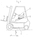
- Figure 1 shows a designed as a forklift truck in a schematic Presentation.
- a vehicle frame 1 a vehicle in the longitudinal direction aligned driver's seat 2, arranged in front of the driver's seat 2 mast 3 and a lifting device vertically movable along the mast 4.
- the driver's seat associated with a control unit 5 for various functions of the truck, in particular the load-carrying means 4.
- the functions of the truck associated movement directions are described below with reference to the drawn rectangular coordinate system described. This corresponds to the Coordinate axis x of the longitudinal direction of the truck, the coordinate axis y the transverse direction of the truck and the coordinate axis z a vertical Direction.
- a basic body 10 of the multi-function lever is part of a driver's seat 2 assigned Armrest 11.
- a handle member 12 of the multi-function lever can relative to the Base body 10 in the direction of all three coordinate axes x, y, z and rotational also be moved around all three coordinate axes x, y, z.
- the Coordinate system of the multi-function lever corresponds to at least approximately the coordinate system of the truck according to FIG. 1.
- the Movements of the handle member 12 associated with other or other functions become.
- the grip element can arbitrarily, for example, after be formed ergonomic point of view.
- FIG. 3 shows an operating unit according to the invention with a multi-function lever, according to the one shown in Fig. 1 and another operating lever 13 for determine the direction of travel of the truck.
- the direction of travel can not then be achieved by moving the grip element 12 of the multi-function lever.
- To operate the truck is thus a first handle member 12 on the multi-function lever and a second Handle member 14 provided on the operating lever 13 for the direction of travel.
- the second Handle element 14 can, starting from the illustrated neutral position to the Transverse axis y of the truck can be swung forwards or backwards, whereby the traction drive of the truck on forward drive or on Reversing is switched.
- the arrangement of the operating lever 13 next to the Multifunction lever proves to be ergonomically favorable, since thereby a fast Enabling is possible.
Landscapes
- Engineering & Computer Science (AREA)
- Transportation (AREA)
- Structural Engineering (AREA)
- Life Sciences & Earth Sciences (AREA)
- Civil Engineering (AREA)
- Combustion & Propulsion (AREA)
- Chemical & Material Sciences (AREA)
- Geology (AREA)
- Mechanical Engineering (AREA)
- Physics & Mathematics (AREA)
- General Physics & Mathematics (AREA)
- Automation & Control Theory (AREA)
- Forklifts And Lifting Vehicles (AREA)
- Mechanical Control Devices (AREA)
Applications Claiming Priority (2)
| Application Number | Priority Date | Filing Date | Title |
|---|---|---|---|
| DE10344029 | 2003-09-23 | ||
| DE10344029A DE10344029A1 (de) | 2003-09-23 | 2003-09-23 | Multifunktionshebel und Bedieneinheit für ein Flurförderzeug |
Publications (3)
| Publication Number | Publication Date |
|---|---|
| EP1518819A2 true EP1518819A2 (fr) | 2005-03-30 |
| EP1518819A3 EP1518819A3 (fr) | 2006-02-08 |
| EP1518819B1 EP1518819B1 (fr) | 2011-05-11 |
Family
ID=34177905
Family Applications (1)
| Application Number | Title | Priority Date | Filing Date |
|---|---|---|---|
| EP04020681A Expired - Lifetime EP1518819B1 (fr) | 2003-09-23 | 2004-08-31 | Manette à fonctions multiples et unité de commande pour chariot de manutention |
Country Status (4)
| Country | Link |
|---|---|
| US (1) | US20050257973A1 (fr) |
| EP (1) | EP1518819B1 (fr) |
| AT (1) | ATE508981T1 (fr) |
| DE (1) | DE10344029A1 (fr) |
Cited By (2)
| Publication number | Priority date | Publication date | Assignee | Title |
|---|---|---|---|---|
| EP1717187A3 (fr) * | 2005-04-26 | 2007-05-30 | Still Gmbh | Chariot de manutention avec une manette à fonctions multiples |
| EP3569771A3 (fr) * | 2018-05-14 | 2019-12-18 | J.C. Bamford Excavators Ltd. | Ensemble de manette pour machine de travail |
Families Citing this family (3)
| Publication number | Priority date | Publication date | Assignee | Title |
|---|---|---|---|---|
| CN101208481B (zh) * | 2005-06-22 | 2011-06-15 | 沃尔沃建造设备控股(瑞典)有限公司 | 一种控制可移动工作机承载工具倾斜的系统及方法,以及一种可移动工作机 |
| DE102013012176A1 (de) * | 2013-07-22 | 2015-01-22 | Jungheinrich Aktiengesellschaft | Bedienelement für ein Flurförderzeug |
| WO2020136830A1 (fr) * | 2018-12-27 | 2020-07-02 | 三菱ロジスネクスト株式会社 | Chariot élévateur à fourche |
Family Cites Families (24)
| Publication number | Priority date | Publication date | Assignee | Title |
|---|---|---|---|---|
| US3040827A (en) * | 1960-05-09 | 1962-06-26 | Yale & Towne Mfg Co | Drive steering for industrial truck |
| US4216467A (en) * | 1977-12-22 | 1980-08-05 | Westinghouse Electric Corp. | Hand controller |
| US4420808A (en) * | 1980-04-01 | 1983-12-13 | United Technologies Corporation | Multi-axis force stick, self-trimmed aircraft flight control system |
| US4555960A (en) * | 1983-03-23 | 1985-12-03 | Cae Electronics, Ltd. | Six degree of freedom hand controller |
| US4702520A (en) * | 1984-10-12 | 1987-10-27 | Deere & Company | Adjustable armrest with integral vehicle controls |
| US4641123A (en) * | 1984-10-30 | 1987-02-03 | Rca Corporation | Joystick control |
| US4755100A (en) * | 1985-11-12 | 1988-07-05 | Clark Equipment Company | Operator control system |
| US4742468A (en) * | 1986-06-16 | 1988-05-03 | Yamate Industrial Co., Ltd. | Lift truck control system |
| US4962448A (en) * | 1988-09-30 | 1990-10-09 | Demaio Joseph | Virtual pivot handcontroller |
| US5589828A (en) * | 1992-03-05 | 1996-12-31 | Armstrong; Brad A. | 6 Degrees of freedom controller with capability of tactile feedback |
| AU2255395A (en) * | 1994-04-11 | 1995-10-30 | Peter Neltoft | Device for use in manual control of the movement of a real or imaginary object |
| DE29502639U1 (de) * | 1995-02-17 | 1995-05-18 | Steinbock Boss GmbH, 85368 Moosburg | Hubstapler |
| US5675359A (en) * | 1995-01-13 | 1997-10-07 | Advanced Technology Systems, Inc. | Joystick controller |
| KR0151349B1 (ko) * | 1995-12-29 | 1998-10-15 | 배순훈 | 운동재현기의 조작장치 |
| WO1998025193A1 (fr) * | 1996-12-04 | 1998-06-11 | Martin Sundin | Dispositif de mesure de position pour la determination de deplacements avec au moins trois degres de liberte |
| GB2325211A (en) * | 1997-05-16 | 1998-11-18 | Lansing Linde Ltd | An operating arrangement for a load supporting device on a lift truck |
| DE19816682A1 (de) * | 1998-04-15 | 1999-10-21 | Still Gmbh | Multifunktionshebel |
| DE29809842U1 (de) * | 1998-06-02 | 1999-10-14 | Steinbock Boss GmbH Fördertechnik, 85368 Moosburg | Flurförderzeug, insbesondere Hubstapler |
| US6129155A (en) * | 1998-12-02 | 2000-10-10 | Caterpillar Inc. | Method and apparatus for controlling a work implement having multiple degrees of freedom |
| USH1831H (en) * | 1998-12-18 | 2000-02-01 | Caterpillar Inc. | Ergonomic motor grader vehicle control apparatus |
| DE50113363D1 (de) * | 2000-10-20 | 2008-01-24 | Deere & Co | Bedienungselement |
| JP3852381B2 (ja) * | 2001-11-29 | 2006-11-29 | トヨタ自動車株式会社 | 車両操作装置 |
| US7474296B2 (en) * | 2002-04-12 | 2009-01-06 | Obermeyer Henry K | Multi-axis joystick and transducer means therefore |
| US7280098B2 (en) * | 2003-05-08 | 2007-10-09 | Komelson Brent A | Joystick housing and mounting bracket |
-
2003
- 2003-09-23 DE DE10344029A patent/DE10344029A1/de not_active Withdrawn
-
2004
- 2004-08-31 AT AT04020681T patent/ATE508981T1/de active
- 2004-08-31 EP EP04020681A patent/EP1518819B1/fr not_active Expired - Lifetime
- 2004-09-22 US US10/947,077 patent/US20050257973A1/en not_active Abandoned
Cited By (3)
| Publication number | Priority date | Publication date | Assignee | Title |
|---|---|---|---|---|
| EP1717187A3 (fr) * | 2005-04-26 | 2007-05-30 | Still Gmbh | Chariot de manutention avec une manette à fonctions multiples |
| EP3569771A3 (fr) * | 2018-05-14 | 2019-12-18 | J.C. Bamford Excavators Ltd. | Ensemble de manette pour machine de travail |
| US11686066B2 (en) | 2018-05-14 | 2023-06-27 | J.C. Bamford Excavators Limited | Working machine joystick assembly |
Also Published As
| Publication number | Publication date |
|---|---|
| EP1518819B1 (fr) | 2011-05-11 |
| EP1518819A3 (fr) | 2006-02-08 |
| DE10344029A1 (de) | 2005-04-14 |
| ATE508981T1 (de) | 2011-05-15 |
| US20050257973A1 (en) | 2005-11-24 |
Similar Documents
| Publication | Publication Date | Title |
|---|---|---|
| EP0950634B1 (fr) | Chariot de manutention avec une manette à fonctions multiples | |
| DE2343297A1 (de) | Mehrfach-steuereinrichtung | |
| DE19749679A1 (de) | Flurförderzeug, insbesondere Kommissioniergerät | |
| DE3925872C2 (fr) | ||
| DE19650338A1 (de) | Flurförderzeug mit einem schwenkbaren Fahrersitz | |
| EP1518819B1 (fr) | Manette à fonctions multiples et unité de commande pour chariot de manutention | |
| DE19623792C2 (de) | Bedienelement für ein deichselgelenktes Flurförderzeug | |
| DE19848191A1 (de) | Schaltgetriebe | |
| DE102005019321A1 (de) | Flurförderzeug mit einem Multifunktionshebel | |
| DE102004005762A1 (de) | Deichselkopf für einen Flurförderer, Flurförderer sowie Verfahren zum Betrieb eines Flurförderers | |
| DE102019109466A1 (de) | Flurförderzeug | |
| EP2946966A1 (fr) | Siège pour un conducteur de véhicule d'un engin, engin, et procédé de réglage d'un siège | |
| EP1247765B1 (fr) | Dispositif de surveillance de charge pour marche-pieds | |
| DE2839903A1 (de) | Anordnung zur handhabung von werkstuecken | |
| DE102011103029A1 (de) | Flurförderzeug mit einer Hubhöhenvorwahleinrichtung | |
| DE69422695T2 (de) | Fahrerkabine für Hebefahrzeuge | |
| DE19615168B4 (de) | Niederhubkommissionierer mit einem Lenkgeber für einen stehenden Fahrer | |
| EP1775254A2 (fr) | Panneau de commande pour un chariot de manutention avec une commande pour le pouce du type joystick | |
| DE19642994C2 (de) | Multifunktionssteuerknüppel | |
| EP1380773A2 (fr) | Dispositif et procédé pour commander une boíte automatique d'un véhicule automobile | |
| DE102018110137B4 (de) | Innenraumkomponente für ein Kraftfahrzeug | |
| EP1203744A1 (fr) | Dispositif de manutention de charge pour un chariot élévateur | |
| DE102014112896B4 (de) | Flurförderzeug mit einer Anzeige- und Bedienvorrichtung | |
| DE4215547A1 (de) | Kombidrehgriff zur Zweihandbedienung zwangsgeführter Flurförderzeuge | |
| DE69700030T2 (de) | Handbediente Einrichtung zur Fernsteuerung der Bewegung eines Gegenstandes in Beziehung auf eine feste Referenz, insbesondere eines Roboters |
Legal Events
| Date | Code | Title | Description |
|---|---|---|---|
| PUAI | Public reference made under article 153(3) epc to a published international application that has entered the european phase |
Free format text: ORIGINAL CODE: 0009012 |
|
| AK | Designated contracting states |
Kind code of ref document: A2 Designated state(s): AT BE BG CH CY CZ DE DK EE ES FI FR GB GR HU IE IT LI LU MC NL PL PT RO SE SI SK TR |
|
| AX | Request for extension of the european patent |
Extension state: AL HR LT LV MK |
|
| PUAL | Search report despatched |
Free format text: ORIGINAL CODE: 0009013 |
|
| AK | Designated contracting states |
Kind code of ref document: A3 Designated state(s): AT BE BG CH CY CZ DE DK EE ES FI FR GB GR HU IE IT LI LU MC NL PL PT RO SE SI SK TR |
|
| AX | Request for extension of the european patent |
Extension state: AL HR LT LV MK |
|
| RIC1 | Information provided on ipc code assigned before grant |
Ipc: G05G 9/047 20060101ALI20051220BHEP Ipc: B66F 9/20 20060101AFI20050113BHEP |
|
| 17P | Request for examination filed |
Effective date: 20060711 |
|
| AKX | Designation fees paid |
Designated state(s): AT BE BG CH CY CZ DE DK EE ES FI FR GB GR HU IE IT LI LU MC NL PL PT RO SE SI SK TR |
|
| 17Q | First examination report despatched |
Effective date: 20061005 |
|
| GRAP | Despatch of communication of intention to grant a patent |
Free format text: ORIGINAL CODE: EPIDOSNIGR1 |
|
| GRAS | Grant fee paid |
Free format text: ORIGINAL CODE: EPIDOSNIGR3 |
|
| GRAA | (expected) grant |
Free format text: ORIGINAL CODE: 0009210 |
|
| AK | Designated contracting states |
Kind code of ref document: B1 Designated state(s): AT BE BG CH CY CZ DE DK EE ES FI FR GB GR HU IE IT LI LU MC NL PL PT RO SE SI SK TR |
|
| REG | Reference to a national code |
Ref country code: GB Ref legal event code: FG4D Free format text: NOT ENGLISH |
|
| REG | Reference to a national code |
Ref country code: CH Ref legal event code: EP |
|
| REG | Reference to a national code |
Ref country code: IE Ref legal event code: FG4D |
|
| REG | Reference to a national code |
Ref country code: DE Ref legal event code: R096 Ref document number: 502004012488 Country of ref document: DE Effective date: 20110622 |
|
| REG | Reference to a national code |
Ref country code: NL Ref legal event code: VDEP Effective date: 20110511 |
|
| PG25 | Lapsed in a contracting state [announced via postgrant information from national office to epo] |
Ref country code: PT Free format text: LAPSE BECAUSE OF FAILURE TO SUBMIT A TRANSLATION OF THE DESCRIPTION OR TO PAY THE FEE WITHIN THE PRESCRIBED TIME-LIMIT Effective date: 20110912 Ref country code: SE Free format text: LAPSE BECAUSE OF FAILURE TO SUBMIT A TRANSLATION OF THE DESCRIPTION OR TO PAY THE FEE WITHIN THE PRESCRIBED TIME-LIMIT Effective date: 20110511 |
|
| PG25 | Lapsed in a contracting state [announced via postgrant information from national office to epo] |
Ref country code: CY Free format text: LAPSE BECAUSE OF FAILURE TO SUBMIT A TRANSLATION OF THE DESCRIPTION OR TO PAY THE FEE WITHIN THE PRESCRIBED TIME-LIMIT Effective date: 20110511 Ref country code: SI Free format text: LAPSE BECAUSE OF FAILURE TO SUBMIT A TRANSLATION OF THE DESCRIPTION OR TO PAY THE FEE WITHIN THE PRESCRIBED TIME-LIMIT Effective date: 20110511 Ref country code: GR Free format text: LAPSE BECAUSE OF FAILURE TO SUBMIT A TRANSLATION OF THE DESCRIPTION OR TO PAY THE FEE WITHIN THE PRESCRIBED TIME-LIMIT Effective date: 20110812 Ref country code: ES Free format text: LAPSE BECAUSE OF FAILURE TO SUBMIT A TRANSLATION OF THE DESCRIPTION OR TO PAY THE FEE WITHIN THE PRESCRIBED TIME-LIMIT Effective date: 20110822 Ref country code: FI Free format text: LAPSE BECAUSE OF FAILURE TO SUBMIT A TRANSLATION OF THE DESCRIPTION OR TO PAY THE FEE WITHIN THE PRESCRIBED TIME-LIMIT Effective date: 20110511 |
|
| REG | Reference to a national code |
Ref country code: IE Ref legal event code: FD4D |
|
| PG25 | Lapsed in a contracting state [announced via postgrant information from national office to epo] |
Ref country code: NL Free format text: LAPSE BECAUSE OF FAILURE TO SUBMIT A TRANSLATION OF THE DESCRIPTION OR TO PAY THE FEE WITHIN THE PRESCRIBED TIME-LIMIT Effective date: 20110511 |
|
| PG25 | Lapsed in a contracting state [announced via postgrant information from national office to epo] |
Ref country code: CZ Free format text: LAPSE BECAUSE OF FAILURE TO SUBMIT A TRANSLATION OF THE DESCRIPTION OR TO PAY THE FEE WITHIN THE PRESCRIBED TIME-LIMIT Effective date: 20110511 Ref country code: EE Free format text: LAPSE BECAUSE OF FAILURE TO SUBMIT A TRANSLATION OF THE DESCRIPTION OR TO PAY THE FEE WITHIN THE PRESCRIBED TIME-LIMIT Effective date: 20110511 Ref country code: IE Free format text: LAPSE BECAUSE OF FAILURE TO SUBMIT A TRANSLATION OF THE DESCRIPTION OR TO PAY THE FEE WITHIN THE PRESCRIBED TIME-LIMIT Effective date: 20110511 |
|
| BERE | Be: lapsed |
Owner name: STILL G.M.B.H. Effective date: 20110831 |
|
| PG25 | Lapsed in a contracting state [announced via postgrant information from national office to epo] |
Ref country code: SK Free format text: LAPSE BECAUSE OF FAILURE TO SUBMIT A TRANSLATION OF THE DESCRIPTION OR TO PAY THE FEE WITHIN THE PRESCRIBED TIME-LIMIT Effective date: 20110511 Ref country code: RO Free format text: LAPSE BECAUSE OF FAILURE TO SUBMIT A TRANSLATION OF THE DESCRIPTION OR TO PAY THE FEE WITHIN THE PRESCRIBED TIME-LIMIT Effective date: 20110511 Ref country code: PL Free format text: LAPSE BECAUSE OF FAILURE TO SUBMIT A TRANSLATION OF THE DESCRIPTION OR TO PAY THE FEE WITHIN THE PRESCRIBED TIME-LIMIT Effective date: 20110511 Ref country code: DK Free format text: LAPSE BECAUSE OF FAILURE TO SUBMIT A TRANSLATION OF THE DESCRIPTION OR TO PAY THE FEE WITHIN THE PRESCRIBED TIME-LIMIT Effective date: 20110511 |
|
| PLBE | No opposition filed within time limit |
Free format text: ORIGINAL CODE: 0009261 |
|
| STAA | Information on the status of an ep patent application or granted ep patent |
Free format text: STATUS: NO OPPOSITION FILED WITHIN TIME LIMIT |
|
| PG25 | Lapsed in a contracting state [announced via postgrant information from national office to epo] |
Ref country code: MC Free format text: LAPSE BECAUSE OF NON-PAYMENT OF DUE FEES Effective date: 20110831 |
|
| REG | Reference to a national code |
Ref country code: CH Ref legal event code: PL |
|
| 26N | No opposition filed |
Effective date: 20120214 |
|
| GBPC | Gb: european patent ceased through non-payment of renewal fee |
Effective date: 20110831 |
|
| PG25 | Lapsed in a contracting state [announced via postgrant information from national office to epo] |
Ref country code: LI Free format text: LAPSE BECAUSE OF NON-PAYMENT OF DUE FEES Effective date: 20110831 Ref country code: CH Free format text: LAPSE BECAUSE OF NON-PAYMENT OF DUE FEES Effective date: 20110831 |
|
| REG | Reference to a national code |
Ref country code: FR Ref legal event code: ST Effective date: 20120430 |
|
| PG25 | Lapsed in a contracting state [announced via postgrant information from national office to epo] |
Ref country code: BE Free format text: LAPSE BECAUSE OF NON-PAYMENT OF DUE FEES Effective date: 20110831 Ref country code: IT Free format text: LAPSE BECAUSE OF FAILURE TO SUBMIT A TRANSLATION OF THE DESCRIPTION OR TO PAY THE FEE WITHIN THE PRESCRIBED TIME-LIMIT Effective date: 20110511 |
|
| REG | Reference to a national code |
Ref country code: DE Ref legal event code: R097 Ref document number: 502004012488 Country of ref document: DE Effective date: 20120214 |
|
| PG25 | Lapsed in a contracting state [announced via postgrant information from national office to epo] |
Ref country code: GB Free format text: LAPSE BECAUSE OF NON-PAYMENT OF DUE FEES Effective date: 20110831 Ref country code: FR Free format text: LAPSE BECAUSE OF NON-PAYMENT OF DUE FEES Effective date: 20110831 |
|
| REG | Reference to a national code |
Ref country code: AT Ref legal event code: MM01 Ref document number: 508981 Country of ref document: AT Kind code of ref document: T Effective date: 20110831 |
|
| PG25 | Lapsed in a contracting state [announced via postgrant information from national office to epo] |
Ref country code: AT Free format text: LAPSE BECAUSE OF NON-PAYMENT OF DUE FEES Effective date: 20110831 |
|
| PG25 | Lapsed in a contracting state [announced via postgrant information from national office to epo] |
Ref country code: LU Free format text: LAPSE BECAUSE OF NON-PAYMENT OF DUE FEES Effective date: 20110831 |
|
| PG25 | Lapsed in a contracting state [announced via postgrant information from national office to epo] |
Ref country code: BG Free format text: LAPSE BECAUSE OF FAILURE TO SUBMIT A TRANSLATION OF THE DESCRIPTION OR TO PAY THE FEE WITHIN THE PRESCRIBED TIME-LIMIT Effective date: 20110811 |
|
| PG25 | Lapsed in a contracting state [announced via postgrant information from national office to epo] |
Ref country code: TR Free format text: LAPSE BECAUSE OF FAILURE TO SUBMIT A TRANSLATION OF THE DESCRIPTION OR TO PAY THE FEE WITHIN THE PRESCRIBED TIME-LIMIT Effective date: 20110511 |
|
| PG25 | Lapsed in a contracting state [announced via postgrant information from national office to epo] |
Ref country code: HU Free format text: LAPSE BECAUSE OF FAILURE TO SUBMIT A TRANSLATION OF THE DESCRIPTION OR TO PAY THE FEE WITHIN THE PRESCRIBED TIME-LIMIT Effective date: 20110511 |
|
| PGFP | Annual fee paid to national office [announced via postgrant information from national office to epo] |
Ref country code: DE Payment date: 20150820 Year of fee payment: 12 |
|
| REG | Reference to a national code |
Ref country code: DE Ref legal event code: R119 Ref document number: 502004012488 Country of ref document: DE |
|
| PG25 | Lapsed in a contracting state [announced via postgrant information from national office to epo] |
Ref country code: DE Free format text: LAPSE BECAUSE OF NON-PAYMENT OF DUE FEES Effective date: 20170301 |