EP1518803A1 - Positionierungsvorrichtung für Bögen in der Zuführstation einer Verarbeitungsmaschine - Google Patents
Positionierungsvorrichtung für Bögen in der Zuführstation einer Verarbeitungsmaschine Download PDFInfo
- Publication number
- EP1518803A1 EP1518803A1 EP04405551A EP04405551A EP1518803A1 EP 1518803 A1 EP1518803 A1 EP 1518803A1 EP 04405551 A EP04405551 A EP 04405551A EP 04405551 A EP04405551 A EP 04405551A EP 1518803 A1 EP1518803 A1 EP 1518803A1
- Authority
- EP
- European Patent Office
- Prior art keywords
- sheet
- sheets
- transverse
- lateral
- positioning
- Prior art date
- Legal status (The legal status is an assumption and is not a legal conclusion. Google has not performed a legal analysis and makes no representation as to the accuracy of the status listed.)
- Granted
Links
- 238000011282 treatment Methods 0.000 title claims description 6
- 238000012545 processing Methods 0.000 claims description 10
- 238000012549 training Methods 0.000 claims description 5
- 210000000056 organ Anatomy 0.000 claims description 4
- 239000000463 material Substances 0.000 claims description 3
- 230000007246 mechanism Effects 0.000 claims description 2
- 210000003141 lower extremity Anatomy 0.000 claims 1
- 230000003287 optical effect Effects 0.000 claims 1
- 238000005520 cutting process Methods 0.000 description 8
- 238000012937 correction Methods 0.000 description 5
- 238000006073 displacement reaction Methods 0.000 description 5
- 239000003550 marker Substances 0.000 description 4
- 238000000034 method Methods 0.000 description 3
- XAGFODPZIPBFFR-UHFFFAOYSA-N aluminium Chemical compound [Al] XAGFODPZIPBFFR-UHFFFAOYSA-N 0.000 description 2
- 229910052782 aluminium Inorganic materials 0.000 description 2
- 230000008901 benefit Effects 0.000 description 2
- 230000007547 defect Effects 0.000 description 2
- 238000001514 detection method Methods 0.000 description 2
- 230000005693 optoelectronics Effects 0.000 description 2
- 230000008569 process Effects 0.000 description 2
- 241000135309 Processus Species 0.000 description 1
- 238000005452 bending Methods 0.000 description 1
- 230000008859 change Effects 0.000 description 1
- 230000006835 compression Effects 0.000 description 1
- 238000007906 compression Methods 0.000 description 1
- 238000013461 design Methods 0.000 description 1
- 239000013013 elastic material Substances 0.000 description 1
- 239000000123 paper Substances 0.000 description 1
- 229920002635 polyurethane Polymers 0.000 description 1
- 239000004814 polyurethane Substances 0.000 description 1
Images


Classifications
-
- B—PERFORMING OPERATIONS; TRANSPORTING
- B65—CONVEYING; PACKING; STORING; HANDLING THIN OR FILAMENTARY MATERIAL
- B65H—HANDLING THIN OR FILAMENTARY MATERIAL, e.g. SHEETS, WEBS, CABLES
- B65H9/00—Registering, e.g. orientating, articles; Devices therefor
- B65H9/10—Pusher and like movable registers; Pusher or gripper devices which move articles into registered position
- B65H9/103—Pusher and like movable registers; Pusher or gripper devices which move articles into registered position acting by friction or suction on the article for pushing or pulling it into registered position, e.g. against a stop
-
- B—PERFORMING OPERATIONS; TRANSPORTING
- B65—CONVEYING; PACKING; STORING; HANDLING THIN OR FILAMENTARY MATERIAL
- B65H—HANDLING THIN OR FILAMENTARY MATERIAL, e.g. SHEETS, WEBS, CABLES
- B65H19/00—Changing the web roll
- B65H19/10—Changing the web roll in unwinding mechanisms or in connection with unwinding operations
Definitions
- the present invention relates to a device for positioning of leaves in an introductory station a processing machine, including a margin table having means for driving said sheets, at least one frontal positioning stop to stop the front edges of said sheets, means for detecting the lateral position of said sheets, means for comparing this position to a reference position, means transverse drive of said sheets and means order to operate these training means in function of the direction and the difference between the lateral position detected from said sheet and said reference position and to stop them when the position of this leaf corresponds to the reference position.
- the sheets In commonly used positioning devices in paper sheet processing machines, of compact cardboard, corrugated cardboard, such as presses multi-station processing, the sheets must be positioned very precisely as well in the sense only transversally to each of the stations that they cross.
- the leaves are fed regularly by a feeder to the margin table which drives the sheets in sheet, allows their taking by the clip bar and their introduction to the stations following.
- the sheet is usually stamped on the margin table first against frontal stops and then against lateral stops by means of feed members such as rollers or bands of elastic material descending support on the table.
- feed members such as rollers or bands of elastic material descending support on the table.
- the problem of positioning the leaves is also particularly delicate when the leaf has undergone various operations such as printing a line upsetting bending, cutting, because the following treatments must be done very exactly with reference to the treatment previous. Despite all the precautions taken, it is produces errors or drifts of the position of the party treated with respect to the front and side edge of the sheet from, for example, successive tilings made in different places from an edge of the leaf that does not are not exactly rectilinear, or tugging being done systematically in the same places leaving marks.
- the cutting of pre-printed elements does not allow any positioning error of the elements to get the desired quality of the finished product.
- US 6,264,196 relates to a document in which when the sheet arrives against mounted stops on a cylinder, it is grasped by a clamp of a device grip carried by a carriage which is held laterally by two opposing compression springs.
- Mon springs is coaxial to a rod and is compressed between the end of the carriage and a shoulder of the rod. The end of this rod carries a roller pressed against a profile a cam, located between two rest sectors 41, 42.
- the gripping device When the sheet comes against the front stops, it is grasped by the gripping device and the roller of the rod is in the rest area of the cam.
- the cylinder turning the roller in a part of the cam profile that causes a lateral displacement of the carriage and therefore of the sheet.
- a brake is activated and stops the truck. The rest of the stroke of the stem is absorbed by the spring.
- US 4'989'855 describes a positioning device in which the cleats are motorized so as to change their position.
- This device comprises reading means for detecting the position of a marker carried by the sheets to be positioned, comparing it with a reference position and adjusting the tabs to correct the position of the sheet.
- Such a device functions as a conventional device and has the same risks, especially with regard to lateral jogging.
- a positioning device without cleat comprising a mobile tablet provided with temporary fixing means of the sheet to be positioned, performing on the one hand a longitudinal displacement of before back and on the other hand correction movement around three vertical pins each secured to a carriage, a central trolley sliding in a slide longitudinal and two side carriages sliding in cross slides.
- the correction movements of this tablet are generated by three linear motors ordered by optoelectronic reading means. The correction occurs during the training of the sheet by the mobile tablet, so as to bring the front edge of the sheet in the forceps of a clip bar in one position precise reference, so that the fastening means temporary tablet can release the sheet and the tablet can be brought back to the starting position for take another sheet.
- This device saves the time required for the jogging of the sheets, which allows to substantially increase the rate of the processing machine.
- EP 1'151'833 relates to a device close to the previous, in which a pinch organ of leaves is connected to the mobile tablet by at least one articulation comprising a plurality of levers forming a parallelogram deformable around a horizontal pivot axis in order to mitigate the appearance of a force component horizontal generated by the levers opening tongs temporarily attaching an edge of the sheet to the tablet.
- EP 1 308 406 discloses a device to detect the position of a side edge of a sheet in an introductory station. According to this device, makes a comparison between the detected position of one side edges of the leaf and the desired position, generates a correction signal which generates a signal of setting transmitted to a setting element to bring that edge lateral in the desired position. So, we act directly on the sheet that we move according to the gap measured between the detected position and the desired position. However, this document gives no indication of the way of implementing this principle.
- the present invention aims to remedy, at least partially, to the usual defects of conventional devices jogging of leaves without leading to a solution likely to significantly increase the cost of the machine of treatment to which the positioning device of leaves is associated.
- the subject of the present invention is a leaf positioning device in a station of introducing a processing machine, according to the claim 1.
- the main advantage of this invention is to associate two positioning modes.
- To position the front edge leaves she uses, as in the devices of classic positioning, front cleats against which the sheet is driven by the margin table, being given that this mode of positioning the front edges of leaves is safe, simple and has no defect notable.
- These front cleats can be fixed or adjustable.
- For lateral positioning a method is used which consists in controlling means for training sheets by optoelectronic means, thus avoiding any use side stops and the disadvantages that arise in particular in the case of flexible sheets.
- the lateral positioning is carried out, as in conventional positioning systems, once the front edge of the sheet is aligned by the front cleats, the only movement to print to the sheet to position it Laterally is a rectilinear motion, which constitutes considerable simplification, both from the point of view of view of the mechanical design as of the electronic control, compared to a mobile system along three axes vertical, as in the aforementioned devices.
- a another important benefit of this invention comes from the fact that the lateral positioning allows a displacement of the leaves in both directions, whereas a mechanical positioning can only pull or push, which does not allows to move the sheet only in one direction.
- the device according to the invention can achieve this positioning on the basis of a benchmark printed. This avoids a repercussion of errors between printing on sheets printed in bobbin and their cut edges by cutting the bobbin, using the print as a reference and no longer the edge of cut sheet and whose angle with the front edge of the sheet to be positioned may vary by a few degrees relative to the perpendicular.
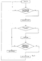
- the positioning process is explained using Figures 1 and 8.
- the sheet 1 to be positioned is driven by a margin table T of a processing machine of sheets, such as a cutting press, a machine of printing, in which the sheet which has just undergone a printing or cutting operation must be positioned precisely for the purpose of a subsequent operation, in order to ensure the same reference position of the sheet for successive operations, so that the position printing or cutting, for example, is not not offset from the cutting or printing operation who preceded it.
- sheet 1 is driven in the direction of arrow F by the table of margin T against a series of front cleats 2, whose position could be adjustable.
- this function is preferably carried out by at least one organ roller press 3, controlled by a cam or pneumatic cylinder (not shown), who presses sheet 1 against a transverse slide 4, arranged between the table of T-margin and the front cleats 2.
- This pressing member 3 could also be replaced by a grasping organ, in particular a suction mouth arranged on the slide transverse and connected to a suction source.
- a cell photoelectric or camera 5 is used to detect an edge side of sheet 1 or, preferably, a marker whose position is characteristic of that of printing or cutting this sheet 1 and comparing its position to a reference position.
- This cell is connected to a entry of a control station 6, an output of which is connected to an actuator, in particular a linear motor 7 for training of the transverse slide 4 according to the gap between the measured lateral position of the leaf and the reference position.
- This control station 6 generates a supply current of a linear motor 7 according to the sense in which the linear motor 7 has to move for bring the edge or marker of sheet 1 into position reference.
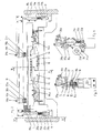
- FIGS 2 to 4 illustrate the device for the positioning of leaves in an introductory station of a processing machine.
- This device comprises a support transverse 8 secured to the frame 9 of the machine treatment that extends to both ends of the support transversal 8.
- This one has at its center an engine linear 7 including a magnet rail 10 having a profile U-shaped, is fixed by screws 11 to this transverse support 8.
- a coil 12, disposed in the magnet rail 10 of linear motor 7, is fixed to a moving part 13 of this linear motor 7 by screws 16.
- This coil 12 is connected at an output of the control station 6 ( Figure 1).
- the part 13, which acts as a transverse slide, is connected to the transverse support 8 by two carriages 14a, 14b arranged on either side of the linear motor 10, 12.
- Each carriage 14a, 14b is engaged with two slides of parallel guiding 15a, 15b ( Figure 3).
- the upper surface of this transverse slide formed by the moving part 13, is secured to a coated aluminum section 17 of a material with a high coefficient of friction such as polyurethane, or having a rough surface condition.
- the positioning device further comprises a profile transversal 18 secured to two vertical slides 19a, 19b mounted in two vertical guides 20a, 20b secured of the frame 9.
- the base of each vertical slide 19a, 19b is pressed by a spring 21a, 21b against a roller 22a, 22b pivoted at the end of an arm of a rocker 23a, 23b pivoted in its center on the frame 9.
- a second roller, of which only the roller 24a is visible in FIG. 4, is pivoted to the other end of the arm of each flip-flop 23a, 23b.
- These second rollers of the latches 23a, 23b are pressed against two respective cams, of which only the cam 25a is visible in FIG. 4, integral with a shaft 26 in kinematic connection with the mechanism drive (not shown) of the processing machine leaves 1.
- Two pairs of pressure rollers 27a, 27b are pivoted freely around axes perpendicular to the cross section 18, so parallel to the F direction in advance of the sheet 1 and secured to two supports 28a, respectively 28b.
- Each support 28a, 28b comprises two adjustment members 29a, 29b, 30a, 30b to adjust the height, respectively the lateral position of each support 28a, 28b.
- Each turn of the control shaft 26 corresponds to a operating cycle of the positioning device at during which the cams 25a, 25b rotate the rockers 23a, 23b, causing the descent of the rollers 27a, 27b against the aluminum profile 17, thus pinching the sheet 1 between this profile 17 and the rollers 27a, 27b after it is brought to bear against the front cleats 2.
- the detection 5 measures the position of the side edge of the sheet 1 or a mark carried by this sheet and transmits the value and the direction of the difference measured at the control station 6. This sends an electric current to the motor coil 12 linear to move the transverse slide 13, constituting the moving part of the linear motor, in the desired direction until the position detected by the cell detection indicates that the lateral position of the sheet 1 corresponds to the reference position.
- This lateral displacement operation of the sheet 1 by the linear motor is performed in synchronism with the rotation of the control shaft 26, so that at the end of the correction, the cams 25a, 25b, integral with the shaft of control 26, rotate the latches 23a, 23b in the direction opposite to that of the hands of the watch ( Figure 4), lifting the slides 19a, 19b and the rollers 27a, 27b.
- the sheet 1 is thus released and the cycle can start again with a following sheet 1.
- the means used for evacuation of the positioned sheet are constituted by a classic clamp bar. This one is not represented insofar as it does not form part of the invention and is not necessary for his understanding.
- this variant comprises a transverse section 31 secured by its two ends 9.
- Each pair of pinch rollers or skids 27a, 27b is then secured to the rod of a jack 32a, 32b, as well as two guide rods 33a, 33b, mounted slidably in the cylinder body 32a, 32b, so that these rollers or pads 27a, 27b are applied against the sheet 1 placed on the moving part 13 of the linear motor at the moment its lateral positioning, by the cylinders 32a, 32b.
- a This variant constitutes a more advantageous solution than the embodiment shown in Figure 2, because less expensive.
Landscapes
- Engineering & Computer Science (AREA)
- Mechanical Engineering (AREA)
- Registering Or Overturning Sheets (AREA)
- Advancing Webs (AREA)
Priority Applications (1)
| Application Number | Priority Date | Filing Date | Title |
|---|---|---|---|
| EP04405551A EP1518803B1 (de) | 2003-09-23 | 2004-09-06 | Positionierungsvorrichtung für Bögen in der Zuführstation einer Verarbeitungsmaschine |
Applications Claiming Priority (3)
| Application Number | Priority Date | Filing Date | Title |
|---|---|---|---|
| EP03405692 | 2003-09-23 | ||
| EP03405692 | 2003-09-23 | ||
| EP04405551A EP1518803B1 (de) | 2003-09-23 | 2004-09-06 | Positionierungsvorrichtung für Bögen in der Zuführstation einer Verarbeitungsmaschine |
Publications (2)
| Publication Number | Publication Date |
|---|---|
| EP1518803A1 true EP1518803A1 (de) | 2005-03-30 |
| EP1518803B1 EP1518803B1 (de) | 2009-10-21 |
Family
ID=34924352
Family Applications (1)
| Application Number | Title | Priority Date | Filing Date |
|---|---|---|---|
| EP04405551A Revoked EP1518803B1 (de) | 2003-09-23 | 2004-09-06 | Positionierungsvorrichtung für Bögen in der Zuführstation einer Verarbeitungsmaschine |
Country Status (4)
| Country | Link |
|---|---|
| EP (1) | EP1518803B1 (de) |
| AT (1) | ATE446268T1 (de) |
| DE (1) | DE602004023679D1 (de) |
| ES (1) | ES2331882T3 (de) |
Families Citing this family (1)
| Publication number | Priority date | Publication date | Assignee | Title |
|---|---|---|---|---|
| DE102010027119A1 (de) | 2010-07-14 | 2012-01-19 | Heidelberger Druckmaschinen Ag | Verfahren und Vorrichtung zum Positionieren von Bogen |
Citations (5)
| Publication number | Priority date | Publication date | Assignee | Title |
|---|---|---|---|---|
| US4591143A (en) * | 1983-03-26 | 1986-05-27 | Heidelberger Druckmaschinen Ag | Apparatus and method for in-register feeding of sheets |
| US4635925A (en) * | 1984-05-12 | 1987-01-13 | Heidelberger Druckmaschinen Ag | Feeding device for sheet processing machines |
| US4989855A (en) * | 1988-05-19 | 1991-02-05 | Bobst Sa | Device for positioning plate-shaped pieces during their transfer into a processing machine |
| US5626458A (en) * | 1994-02-24 | 1997-05-06 | Bobst Sa | Device for sidewise alignment of flat workpieces on a table |
| US6264196B1 (en) * | 1996-05-04 | 2001-07-24 | Heidelberger Druckmaschinen Ag | Method and device for laterally aligning a sheet |
-
2004
- 2004-09-06 ES ES04405551T patent/ES2331882T3/es not_active Expired - Lifetime
- 2004-09-06 EP EP04405551A patent/EP1518803B1/de not_active Revoked
- 2004-09-06 AT AT04405551T patent/ATE446268T1/de not_active IP Right Cessation
- 2004-09-06 DE DE602004023679T patent/DE602004023679D1/de not_active Expired - Lifetime
Patent Citations (5)
| Publication number | Priority date | Publication date | Assignee | Title |
|---|---|---|---|---|
| US4591143A (en) * | 1983-03-26 | 1986-05-27 | Heidelberger Druckmaschinen Ag | Apparatus and method for in-register feeding of sheets |
| US4635925A (en) * | 1984-05-12 | 1987-01-13 | Heidelberger Druckmaschinen Ag | Feeding device for sheet processing machines |
| US4989855A (en) * | 1988-05-19 | 1991-02-05 | Bobst Sa | Device for positioning plate-shaped pieces during their transfer into a processing machine |
| US5626458A (en) * | 1994-02-24 | 1997-05-06 | Bobst Sa | Device for sidewise alignment of flat workpieces on a table |
| US6264196B1 (en) * | 1996-05-04 | 2001-07-24 | Heidelberger Druckmaschinen Ag | Method and device for laterally aligning a sheet |
Also Published As
| Publication number | Publication date |
|---|---|
| DE602004023679D1 (de) | 2009-12-03 |
| EP1518803B1 (de) | 2009-10-21 |
| ATE446268T1 (de) | 2009-11-15 |
| ES2331882T3 (es) | 2010-01-19 |
Similar Documents
| Publication | Publication Date | Title |
|---|---|---|
| EP1044908B1 (de) | Verfahren zum Positionieren von plattenförmigen Gegenständen in der Zuführstation einer Verarbeitungsmaschine und Vorrichtung zur Durchführung des Verfahrens | |
| CH621882A5 (de) | ||
| FR2597519A1 (fr) | Appareil et procede pour couper du tissu-eponge | |
| EP0039526B1 (de) | Transportvorrichtung zur Überführung von frisch bedruckten Bogen | |
| JP4265745B2 (ja) | 製函装置 | |
| BE1000097A6 (fr) | Appareil pour aligner des feuilles de verre dans une ligne de production, notamment de pare-brise. | |
| FR2765191A1 (fr) | Procede et machine de collage automatique d'un film plastique thermoretractable sur le fond d'une caisse ouverte | |
| EP1518803B1 (de) | Positionierungsvorrichtung für Bögen in der Zuführstation einer Verarbeitungsmaschine | |
| EP1151833B1 (de) | Vorrichtung zum Positionieren von Bögen in einer Maschinenstation | |
| CH560106A5 (en) | Printing head assembly using ink ribbon - head is controlled by spring loaded lever connected to head | |
| JPH08106131A (ja) | リール材の把持装置 | |
| JP3891371B2 (ja) | プリンタ | |
| EP0972639A1 (de) | Vorrichtung zum Einstellen einer flexiblen Druckplatte auf einem Formzylinder | |
| JP3891370B2 (ja) | プリンタ | |
| JP2007216682A (ja) | ブックブロック搬送システム | |
| FR2668976A1 (fr) | Dispositif pour amener et aligner des feuilles de papier sur une table de marge de machines d'impression. | |
| FR3024976A1 (fr) | Dispositif et procede de pose d'une poignee adhesive sur un fardeau en deplacement | |
| JP2009523622A (ja) | 被加工物搬送装置 | |
| EP0125945B1 (de) | Verfahren und Vorrichtung zum Transferieren und Positionieren von Werkstücken | |
| EP1524221B1 (de) | Ausbrechstation einer Stanzpresse | |
| EP0449681A1 (de) | Einrichtung zum automatischen Zuführen von Blechen in eine Presse bzw. in eine Maschine beliebig anderer Art | |
| EP2374719B1 (de) | Anlage zum Aufbringen von Klebesegmenten auf durchlaufende Pakete | |
| FR2796000A1 (fr) | Dispositif et procede d'embossage de cartes plastiques | |
| EP1522512B1 (de) | Arbeitsstation einer Umwandlungsmaschine für plattenförmige Elemente | |
| FR2477504A1 (fr) | Dispositif pour le pliage et le collage de bandes adhesives sur des documents plats |
Legal Events
| Date | Code | Title | Description |
|---|---|---|---|
| PUAI | Public reference made under article 153(3) epc to a published international application that has entered the european phase |
Free format text: ORIGINAL CODE: 0009012 |
|
| AK | Designated contracting states |
Kind code of ref document: A1 Designated state(s): AT BE BG CH CY CZ DE DK EE ES FI FR GB GR HU IE IT LI LU MC NL PL PT RO SE SI SK TR |
|
| AX | Request for extension of the european patent |
Extension state: AL HR LT LV MK |
|
| 17P | Request for examination filed |
Effective date: 20050427 |
|
| AKX | Designation fees paid |
Designated state(s): AT BE BG CH CY CZ DE DK EE ES FI FR GB GR HU IE IT LI LU MC NL PL PT RO SE SI SK TR |
|
| 17Q | First examination report despatched |
Effective date: 20051108 |
|
| GRAP | Despatch of communication of intention to grant a patent |
Free format text: ORIGINAL CODE: EPIDOSNIGR1 |
|
| GRAS | Grant fee paid |
Free format text: ORIGINAL CODE: EPIDOSNIGR3 |
|
| GRAA | (expected) grant |
Free format text: ORIGINAL CODE: 0009210 |
|
| AK | Designated contracting states |
Kind code of ref document: B1 Designated state(s): AT BE BG CH CY CZ DE DK EE ES FI FR GB GR HU IE IT LI LU MC NL PL PT RO SE SI SK TR |
|
| REG | Reference to a national code |
Ref country code: GB Ref legal event code: FG4D Free format text: NOT ENGLISH |
|
| REG | Reference to a national code |
Ref country code: CH Ref legal event code: EP |
|
| REG | Reference to a national code |
Ref country code: IE Ref legal event code: FG4D |
|
| REF | Corresponds to: |
Ref document number: 602004023679 Country of ref document: DE Date of ref document: 20091203 Kind code of ref document: P |
|
| REG | Reference to a national code |
Ref country code: ES Ref legal event code: FG2A Ref document number: 2331882 Country of ref document: ES Kind code of ref document: T3 |
|
| NLV1 | Nl: lapsed or annulled due to failure to fulfill the requirements of art. 29p and 29m of the patents act | ||
| PG25 | Lapsed in a contracting state [announced via postgrant information from national office to epo] |
Ref country code: FI Free format text: LAPSE BECAUSE OF FAILURE TO SUBMIT A TRANSLATION OF THE DESCRIPTION OR TO PAY THE FEE WITHIN THE PRESCRIBED TIME-LIMIT Effective date: 20091021 Ref country code: SE Free format text: LAPSE BECAUSE OF FAILURE TO SUBMIT A TRANSLATION OF THE DESCRIPTION OR TO PAY THE FEE WITHIN THE PRESCRIBED TIME-LIMIT Effective date: 20091021 Ref country code: PT Free format text: LAPSE BECAUSE OF FAILURE TO SUBMIT A TRANSLATION OF THE DESCRIPTION OR TO PAY THE FEE WITHIN THE PRESCRIBED TIME-LIMIT Effective date: 20100222 |
|
| REG | Reference to a national code |
Ref country code: IE Ref legal event code: FD4D |
|
| PG25 | Lapsed in a contracting state [announced via postgrant information from national office to epo] |
Ref country code: PL Free format text: LAPSE BECAUSE OF FAILURE TO SUBMIT A TRANSLATION OF THE DESCRIPTION OR TO PAY THE FEE WITHIN THE PRESCRIBED TIME-LIMIT Effective date: 20091021 Ref country code: SI Free format text: LAPSE BECAUSE OF FAILURE TO SUBMIT A TRANSLATION OF THE DESCRIPTION OR TO PAY THE FEE WITHIN THE PRESCRIBED TIME-LIMIT Effective date: 20091021 |
|
| PG25 | Lapsed in a contracting state [announced via postgrant information from national office to epo] |
Ref country code: AT Free format text: LAPSE BECAUSE OF FAILURE TO SUBMIT A TRANSLATION OF THE DESCRIPTION OR TO PAY THE FEE WITHIN THE PRESCRIBED TIME-LIMIT Effective date: 20091021 |
|
| PLBI | Opposition filed |
Free format text: ORIGINAL CODE: 0009260 |
|
| PG25 | Lapsed in a contracting state [announced via postgrant information from national office to epo] |
Ref country code: DK Free format text: LAPSE BECAUSE OF FAILURE TO SUBMIT A TRANSLATION OF THE DESCRIPTION OR TO PAY THE FEE WITHIN THE PRESCRIBED TIME-LIMIT Effective date: 20091021 Ref country code: BG Free format text: LAPSE BECAUSE OF FAILURE TO SUBMIT A TRANSLATION OF THE DESCRIPTION OR TO PAY THE FEE WITHIN THE PRESCRIBED TIME-LIMIT Effective date: 20100121 Ref country code: RO Free format text: LAPSE BECAUSE OF FAILURE TO SUBMIT A TRANSLATION OF THE DESCRIPTION OR TO PAY THE FEE WITHIN THE PRESCRIBED TIME-LIMIT Effective date: 20091021 Ref country code: IE Free format text: LAPSE BECAUSE OF FAILURE TO SUBMIT A TRANSLATION OF THE DESCRIPTION OR TO PAY THE FEE WITHIN THE PRESCRIBED TIME-LIMIT Effective date: 20091021 Ref country code: EE Free format text: LAPSE BECAUSE OF FAILURE TO SUBMIT A TRANSLATION OF THE DESCRIPTION OR TO PAY THE FEE WITHIN THE PRESCRIBED TIME-LIMIT Effective date: 20091021 |
|
| 26 | Opposition filed |
Opponent name: HEIDELBERGER DRUCKMASCHINEN AG Effective date: 20100623 |
|
| PLAX | Notice of opposition and request to file observation + time limit sent |
Free format text: ORIGINAL CODE: EPIDOSNOBS2 |
|
| PG25 | Lapsed in a contracting state [announced via postgrant information from national office to epo] |
Ref country code: CZ Free format text: LAPSE BECAUSE OF FAILURE TO SUBMIT A TRANSLATION OF THE DESCRIPTION OR TO PAY THE FEE WITHIN THE PRESCRIBED TIME-LIMIT Effective date: 20091021 Ref country code: SK Free format text: LAPSE BECAUSE OF FAILURE TO SUBMIT A TRANSLATION OF THE DESCRIPTION OR TO PAY THE FEE WITHIN THE PRESCRIBED TIME-LIMIT Effective date: 20091021 |
|
| PG25 | Lapsed in a contracting state [announced via postgrant information from national office to epo] |
Ref country code: GR Free format text: LAPSE BECAUSE OF FAILURE TO SUBMIT A TRANSLATION OF THE DESCRIPTION OR TO PAY THE FEE WITHIN THE PRESCRIBED TIME-LIMIT Effective date: 20100122 |
|
| BERE | Be: lapsed |
Owner name: BOBST S.A. Effective date: 20100930 |
|
| PG25 | Lapsed in a contracting state [announced via postgrant information from national office to epo] |
Ref country code: MC Free format text: LAPSE BECAUSE OF NON-PAYMENT OF DUE FEES Effective date: 20100930 |
|
| PG25 | Lapsed in a contracting state [announced via postgrant information from national office to epo] |
Ref country code: BE Free format text: LAPSE BECAUSE OF NON-PAYMENT OF DUE FEES Effective date: 20100930 |
|
| PGFP | Annual fee paid to national office [announced via postgrant information from national office to epo] |
Ref country code: CH Payment date: 20110902 Year of fee payment: 8 |
|
| PGFP | Annual fee paid to national office [announced via postgrant information from national office to epo] |
Ref country code: DE Payment date: 20110831 Year of fee payment: 8 Ref country code: GB Payment date: 20110831 Year of fee payment: 8 Ref country code: FR Payment date: 20110915 Year of fee payment: 8 |
|
| RDAF | Communication despatched that patent is revoked |
Free format text: ORIGINAL CODE: EPIDOSNREV1 |
|
| REG | Reference to a national code |
Ref country code: DE Ref legal event code: R064 Ref document number: 602004023679 Country of ref document: DE Ref country code: DE Ref legal event code: R103 Ref document number: 602004023679 Country of ref document: DE |
|
| PGFP | Annual fee paid to national office [announced via postgrant information from national office to epo] |
Ref country code: IT Payment date: 20110914 Year of fee payment: 8 |
|
| PGFP | Annual fee paid to national office [announced via postgrant information from national office to epo] |
Ref country code: ES Payment date: 20111017 Year of fee payment: 8 |
|
| RDAG | Patent revoked |
Free format text: ORIGINAL CODE: 0009271 |
|
| STAA | Information on the status of an ep patent application or granted ep patent |
Free format text: STATUS: PATENT REVOKED |
|
| REG | Reference to a national code |
Ref country code: CH Ref legal event code: PL |
|
| 27W | Patent revoked |
Effective date: 20111218 |
|
| GBPR | Gb: patent revoked under art. 102 of the ep convention designating the uk as contracting state |
Effective date: 20111218 |
|
| PG25 | Lapsed in a contracting state [announced via postgrant information from national office to epo] |
Ref country code: CH Free format text: LAPSE BECAUSE OF THE APPLICANT RENOUNCES Effective date: 20091021 Ref country code: LI Free format text: LAPSE BECAUSE OF THE APPLICANT RENOUNCES Effective date: 20091021 |
|
| REG | Reference to a national code |
Ref country code: DE Ref legal event code: R107 Ref document number: 602004023679 Country of ref document: DE Effective date: 20120614 |
|
| PG25 | Lapsed in a contracting state [announced via postgrant information from national office to epo] |
Ref country code: CY Free format text: LAPSE BECAUSE OF FAILURE TO SUBMIT A TRANSLATION OF THE DESCRIPTION OR TO PAY THE FEE WITHIN THE PRESCRIBED TIME-LIMIT Effective date: 20091021 |
|
| PG25 | Lapsed in a contracting state [announced via postgrant information from national office to epo] |
Ref country code: LU Free format text: LAPSE BECAUSE OF REVOCATION BY EPO Effective date: 20100906 Ref country code: HU Free format text: LAPSE BECAUSE OF FAILURE TO SUBMIT A TRANSLATION OF THE DESCRIPTION OR TO PAY THE FEE WITHIN THE PRESCRIBED TIME-LIMIT Effective date: 20100422 |
|
| PG25 | Lapsed in a contracting state [announced via postgrant information from national office to epo] |
Ref country code: NL Free format text: LAPSE BECAUSE OF NON-PAYMENT OF DUE FEES Effective date: 20091021 |