EP1518733B1 - Toit de véhicule avec ouverture de toit et un déflecteur de vent - Google Patents
Toit de véhicule avec ouverture de toit et un déflecteur de vent Download PDFInfo
- Publication number
- EP1518733B1 EP1518733B1 EP04022662A EP04022662A EP1518733B1 EP 1518733 B1 EP1518733 B1 EP 1518733B1 EP 04022662 A EP04022662 A EP 04022662A EP 04022662 A EP04022662 A EP 04022662A EP 1518733 B1 EP1518733 B1 EP 1518733B1
- Authority
- EP
- European Patent Office
- Prior art keywords
- wind deflector
- roof
- vehicle roof
- roof according
- vehicle
- Prior art date
- Legal status (The legal status is an assumption and is not a legal conclusion. Google has not performed a legal analysis and makes no representation as to the accuracy of the status listed.)
- Not-in-force
Links
Images


Classifications
-
- B—PERFORMING OPERATIONS; TRANSPORTING
- B60—VEHICLES IN GENERAL
- B60J—WINDOWS, WINDSCREENS, NON-FIXED ROOFS, DOORS, OR SIMILAR DEVICES FOR VEHICLES; REMOVABLE EXTERNAL PROTECTIVE COVERINGS SPECIALLY ADAPTED FOR VEHICLES
- B60J7/00—Non-fixed roofs; Roofs with movable panels, e.g. rotary sunroofs
- B60J7/22—Wind deflectors for open roofs
Definitions
- the present invention relates to a vehicle roof with a roof opening and a wind deflector according to the preamble of claim 1.
- Generic vehicle roofs are known, in which the wind deflector is mounted pivotably about a roof-mounted roof axis extending axis and resiliently biased towards the fully deployed position, the wind deflector is lowered when closing the closing element or the lid by means of the cover drive against the biasing force, and wherein the holder acting on the wind deflector acts as a hold-down in the intermediate positions.
- Such a generic vehicle roof is for example in the DE 199 58 742 A1 described, wherein the adjusting device is arranged in the region of the front edge of the roof opening and is provided with a lever mechanism having two mirror-symmetrical actuating rockers, one end of which forms a stop for the wind deflector and the other end is articulated to a control lever which is on an output shaft the actuator is seated.
- the disadvantage of this solution is the relatively large installation space.
- a similar construction is known, wherein the stop for the wind deflector is determined by a wire of a shape memory alloy.
- a vehicle roof is described in which the wind deflector position is adjustable via an acting on the wind deflector cable.
- a vehicle roof is known in which the stop for the Windabweiserauswolf via actuated by the cover side control lever.
- a similar vehicle roof is also in the DE 198 09 943 A1 described.
- DE 197 01 479 A1 is a vehicle roof described in which the wind deflector is displaced via a displaceable by a servomotor in the roof longitudinal direction driven side cam, which is designed as a link belt, for example in the form of a vertically arranged toothed belt.
- a vehicle roof in which the wind deflector is pivotable about a pivot axis extending at its front end in the roof transverse direction, wherein a provided with an inclined slide track link element is firmly connected to the wind deflector and wherein a driven to a sliding movement in the roof transverse direction guide pin with the slide track is engaged, that in a sliding movement of the guide pin in the roof transverse direction pivoting of the link element and thus the wind deflector takes place.
- a vehicle roof in which the stop for the raising movement of the wind deflector is adjustable by means of one end of a control lever designed as a rocker whose other end is controlled by a running in the roof longitudinal slot slot via a separate motor.
- a vehicle roof in which a wind deflector is provided in the region of its upper edge with additional elements which are mounted on the wind deflector so that they can be pushed over the top edge of the wind deflector if necessary, this being done by one of a Drive in the roof transverse direction driven guide pin in each case slidably engages in an inclined slide track on the respective additional element.
- the adjusting device in a simple manner, the position of the wind deflector, for example, depending on the driving speed and / or the degree of opening of the closing element, can be varied in order to achieve an optimal reduction of wind and Wummer noises
- the adjusting device can be designed very compact with low space requirements and can be integrated in particular in the front transverse part of a roof frame for the closing element, further wherein the number of additional parts required for the adjusting device can be kept very low and wherein the Adjusting device can be made very robust and thus reliable.
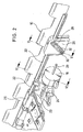
- Fig. 1 13 is a schematic perspective view, seen obliquely from the front, of a wind deflector 10 and the front, transversal part of a roof roof 12 for a vehicle roof, the vehicle roof having a roof opening (not shown), which is supported by an adjustable closing element (not shown). optionally closed or at least partially exposed.
- the wind deflector 10 and the part of the roof frame 12 shown are arranged in the region of the front edge of the roof opening, wherein the Roof frame serves as a storage for the closing element.
- the deflector extends over the entire width of the roof opening.
- the closing element may be, for example, the cover of a sliding roof, sliding roof, externally guided sliding roof or spoiler roof or the slats of a slatted roof.
- the wind deflector 10 includes a front Windabweiser nature and two lateral arms 14 which are pivotally mounted at its rear end at 16 about a extending in the roof transverse direction fixed axis.
- the wind deflector 10 is biased in the manner of known manner by means of a spring element in a fully flared position in which the front Windabweiser construction is issued above the fixed roof surface to Windund Wummer noises when driving with open Closing element occur to eliminate or reduce.
- closing the closing element of the wind deflector is pressed against the spring bias with its front surface down in a trained in the roof frame storage space or lowered, this is done by operating the lateral arms 14 when closing the closing element.
- the fully deployed position of the wind deflector 10 is predetermined by a fixed stop (not shown). In general, however, it is desirable under some circumstances to adjust the wind deflector 10 also in intermediate positions between the lowered and fully deployed positions. Thus, noisy noises mainly occur in a lower speed range (for example, up to 100 km / h), so that in this range usually the fully deployed position of the wind deflector 10 is desirable, while at higher speeds barely whining noises occur, so that in this Speed range is not required to fully expose the deflector.
- an adjusting device described below which has a servomotor 18, which may be designed, for example, as a rotary motor, which can be adjusted in the transverse roof direction Spindle 20 drives, and a rod-like extending in the roof transverse direction zugtiksteifes element 22, which is driven by a coupling assembly 24 from the spindle 20 to a sliding movement in the roof transverse direction and on a guide rail 23 which is formed on the roof frame 12 and provided with a cover 25 , slidably guided in roof transverse direction.
- a servomotor 18 which may be designed, for example, as a rotary motor, which can be adjusted in the transverse roof direction Spindle 20 drives, and a rod-like extending in the roof transverse direction zugdrucksteifes element 22, which is driven by a coupling assembly 24 from the spindle 20 to a sliding movement in the roof transverse direction and on a guide rail 23 which is formed on the roof frame 12 and provided with a cover 25 , slidably guided in roof transverse
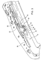
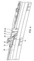
- the adjusting device further comprises a guide element formed as a link element 26, which forms part of the tension-pressure-resistant element 22 or is fixedly connected thereto and has an inclined link slot 28, in which engages an engagement element designed as a link pin or bolt 30, see in particular Fig. 2 ,
- the guide pin 30 is further guided in a in the roof vertical direction, ie substantially perpendicular to the direction of movement of the link element 26 and formed in the roof frame 12 slide track 32 that it only perpendicular to the direction of movement of the link element 26 (ie in the example shown only in FIG the roof upward direction) is displaceable, see FIGS. 2 . 3 .
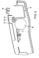
- the guide pin 30 is connected at its rear by means of a flexible member 34, which may be formed, for example, as a band, with a hold-down 36, which is in firm engagement with the wind deflector 10, see in particular Fig. 5 ,
- the servomotor can also be designed as a linear motor.
- the adjusting device for the wind deflector 10 will be explained in more detail. If, for example, a lowering of the wind deflector 10 starting from the fully deployed position is desired when the closing element is open, for example, because a predetermined speed threshold is exceeded, the servo motor is correspondingly driven to a rotational movement, which causes a displacement of the spindle 20 in the roof transverse direction.
- the control of the servomotor 18 could, for example, also take place as a function of the degree of opening of the closing element.
- the flexible element 34 ensures a karsteife, but not for a pressure-resistant connection between the guide pin 30 and the hold-down 36.
- the wind deflector can be brought by means of the servomotor 18 in the fully lowered position, as this usually occurs anyway when closing the closing element by actuation of the lateral arms 14 (in such a case, a flexibility of the connecting element 34 required).
- Fig. 1 is provided in a symmetrical arrangement in the vicinity of the lateral edge respectively on both sides of one of the link elements 26, which are driven jointly by the servo motor 18, whereby each of the hold-36 engages spaced at roof transverse direction points.
- the entire adjusting device is arranged in the region of the front part of the roof frame 12 and at least partially integrated in this.
- the roof frame acts as a body-mounted support for the adjusting device.
- the wind deflector 10 may instead of in Fig. 1 embodiment shown with two lateral arms 14 may alternatively be formed as Windabweiserlamelle which is rotatable about a extending in the roof transverse direction at or near the front end of the Windabweiserlamelle axis of rotation with its trailing edge.
- the hold-down expediently engage in the vicinity of the trailing edge of the wind deflector blade in order to lower it in intermediate positions.
- the displaceable in the roof transverse direction guide element in the example shown, the link element 26
- the engagement element in particular as a guide pin is formed while in the roof top direction displaceable element (in the example shown, the guide pin 30) is provided with an inclined slide track or track, with which the engagement member is slidably engaged.
- the guideway does not necessarily have to be formed as a slotted slot, but also in other ways, for example, as a guide bar, may be formed, wherein the engagement member does not necessarily have to be designed as a guide pin, but for example as the guide bar encompassing shoe formed can be.
- the adjusting mechanism shown could be used not only for lowering the wind deflector, but also for issuing the same, in which case the connection between the engagement member and the hold-down not only zugsteif, but should also be designed to be pressure-resistant. In this case, then the adjusting mechanism could in principle be used to reach the end positions of the wind deflector.
Claims (27)
- Toit de véhicule avec une ouverture de toit, un élément de fermeture déplaçable pour fermer ou au moins ouvrir en partie l'ouverture de toit, un déflecteur de vent (10) disposé dans la région du bord avant de l'ouverture de toit, qui peut être déplacé entre une position rentrée et une position complètement sortie, ainsi qu'un dispositif de commande (18, 20, 22, 26, 30) pour ajuster des positions intermédiaires du déflecteur de vent, lequel présente un dispositif de fixation (36) venant en prise sur le déflecteur de vent et un mécanisme de déplacement (22, 26, 30) entraîné par un entraînement (18, 20), au moyen duquel le dispositif de fixation peut être déplacé en hauteur pour prédéfinir des positions intermédiaires du déflecteur de vent, caractérisé en ce que le mécanisme de déplacement présente un élément de guidage (26) entraîné par l'entraînement de manière à se déplacer le long du déflecteur de vent, avec une piste de guidage inclinée (28), le long de laquelle un élément d'engagement (30) connecté au dispositif de fixation (36) est guidé de manière déplaçable, l'élément d'engagement étant monté sur un support (12, 32) fixé à la carrosserie de telle sorte qu'il puisse être déplacé par rapport au support seulement perpendiculairement à la direction de déplacement de l'élément de guidage.
- Toit de véhicule selon la revendication 1, caractérisé en ce que la piste de guidage est réalisée sous forme de piste à coulisse (28).
- Toit de véhicule selon la revendication 2, caractérisé en ce que la piste à coulisse est réalisée sous forme de fente à coulisse (28) et l'élément d'engagement est réalisé sous la forme d'une broche à coulisse (30) guidée dans la fente à coulisse.
- Toit de véhicule selon la revendication 2 ou 3, caractérisé en ce que l'élément d'engagement (30) est guidé sur le support (12) fixé à la carrosserie de manière déplaçable dans une piste à coulisse s'étendant dans la direction montante du toit.
- Toit de véhicule selon l'une quelconque des revendications précédentes, caractérisé en ce que l'élément de guidage (26) est entraîné de manière à se déplacer dans la direction transversale du toit le long de la région avant du déflecteur de vent (10).
- Toit de véhicule selon l'une quelconque des revendications précédentes, caractérisé en ce que le déflecteur de vent (10) est précontraint vers la position complètement sortie.
- Toit de véhicule selon la revendication 6, caractérisé en ce que le déflecteur de vent (10) est abaissé par la fermeture de l'élément de fermeture à l'encontre de la force de précontrainte.
- Toit de véhicule selon la revendication 6 ou 7, caractérisé en ce que le dispositif de fixation agit à l'encontre de la force de précontrainte pour prédéfinir les positions intermédiaires du déflecteur de vent (10) en tant que dispositif de retenue (36).
- Toit de véhicule selon la revendication 8, caractérisé en ce que le dispositif de fixation (36) est connecté à l'élément d'engagement (30) au moyen d'un élément flexible (34).
- Toit de véhicule selon la revendication 9, caractérisé en ce que l'élément flexible (34) est réalisé sous forme de connexion rigide en traction, mais pas en pression, notamment sous forme de bande.
- Toit de véhicule selon l'une quelconque des revendications précédentes, caractérisé en ce que le déflecteur de vent (10) s'étend sur toute la largeur de l'ouverture du toit.
- Toit de véhicule selon l'une quelconque des revendications précédentes, caractérisé en ce que le déflecteur de vent (10) peut pivoter autour d'un axe fixé à la carrosserie et s'étendant dans la direction transversale du toit.
- Toit de véhicule selon la revendication 12, caractérisé en ce que l'axe de pivotement se situe à l'extrémité arrière (16) du déflecteur de vent (10).
- Toit de véhicule selon l'une quelconque des revendications précédentes, caractérisé en ce que l'élément de guidage (26) est connecté à l'entraînement (18, 20) au moyen d'un élément rigide en traction et en pression (22), qui est guidé le long d'un guide (23) réalisé sur le support (12) fixé à la carrosserie.
- Toit de véhicule selon la revendication 14, caractérisé en ce que l'élément de guidage (26) est réalisé d'une seule pièce avec l'élément rigide en traction et en pression (22).
- Toit de véhicule selon l'une quelconque des revendications précédentes, caractérisé en ce que l'entraînement présente un moteur de commande qui est réalisé sous forme de moteur linéaire ou de moteur rotatif (18) avec un agencement (20) monté en aval, pour convertir un mouvement de rotation en un mouvement linéaire.
- Toit de véhicule selon la revendication 16, caractérisé en ce que l'entraînement est formé par une broche (20) entraînée par un moteur rotatif (18).
- Toit de véhicule selon la revendication 17, caractérisé en ce que la broche (20) est connectée au moyen d'un élément d'accouplement (24) à l'élément rigide en traction et en pression (22).
- Toit de véhicule selon l'une quelconque des revendications précédentes, caractérisé en ce que l'entraînement (18, 20) est commandé en fonction de la vitesse de conduite et/ou du degré d'ouverture de l'élément de fermeture.
- Toit de véhicule selon l'une quelconque des revendications précédentes, caractérisé en ce qu'au moins deux des mécanismes de commande (26, 30) et deux des dispositifs de fixation (36) sont prévus, les mécanismes de commande étant entraînés par un entraînement commun (18, 20).
- Toit de véhicule selon la revendication 20, caractérisé en ce que les dispositifs de fixation (36) viennent en prise dans des emplacements espacés dans la direction transversale du toit, en particulier à chaque fois dans la région de bord latérale du déflecteur de vent (10).
- Toit de véhicule selon l'une quelconque des revendications précédentes, caractérisé en ce que le dispositif de commande (18, 20, 22, 26, 30) en entier est disposé dans la région du bord avant de l'ouverture de toit.
- Toit de véhicule selon la revendication 22, caractérisé en ce que le support fixé à la carrosserie est la portion avant s'étendant dans la direction transversale du toit, d'un cadre (12) disposé sous l'ouverture du toit.
- Toit de véhicule selon la revendication 23, caractérisé en ce que le dispositif de commande (20, 22, 26, 30) est intégré au moins en partie dans le support fixé à la carrosserie.
- Toit de véhicule selon l'une quelconque des revendications précédentes, caractérisé en ce que l'élément de fermeture est réalisé sous forme de couvercle, notamment d'un toit coulissant, d'un toit ouvrant coulissant et relevable, d'un toit ouvrant coulissant guidé à l'extérieur ou d'un toit à spoiler, ou sous forme de toit ouvrant à lamelles.
- Toit de véhicule selon la revendication 12, caractérisé en ce que le déflecteur de vent est réalisé sous forme de lamelle de déflecteur de vent, qui peut être sortie avec son arête arrière.
- Toit de véhicule comprenant une ouverture de toit, un élément de fermeture, qui est déplaçable, pour fermer ou au moins ouvrir en partie l'ouverture de toit, un déflecteur de vent (10) disposé dans la région du bord avant de l'ouverture de toit, qui peut être déplacé entre une position rentrée et une position complètement sortie, ainsi qu'un dispositif de commande (18, 20, 22, 26, 30) pour ajuster des positions intermédiaires du déflecteur de vent, qui présente un dispositif de fixation (36) venant en prise avec le déflecteur de vent et un mécanisme de déplacement (22, 26, 30) entraîné par un entraînement (18, 20), au moyen duquel le dispositif de fixation peut être déplacé en hauteur pour prédéfinir des positions intermédiaires du déflecteur de vent, caractérisé en ce que le mécanisme de déplacement présente un élément d'engagement entraîné par l'entraînement de manière à se déplacer le long du déflecteur de vent, lequel est en prise déplaçable avec une piste de guidage inclinée d'un élément de guidage connecté fixement au dispositif de fixation, l'élément de guidage étant monté sur un support fixé à la carrosserie de telle sorte qu'il puisse être déplacé par rapport au support uniquement perpendiculairement à la direction de déplacement de l'élément d'engagement.
Applications Claiming Priority (2)
| Application Number | Priority Date | Filing Date | Title |
|---|---|---|---|
| DE10344884A DE10344884B3 (de) | 2003-09-26 | 2003-09-26 | Fahrzeugdach mit einer Dachöffnung und einem Windabweiser |
| DE10344884 | 2003-09-26 |
Publications (3)
| Publication Number | Publication Date |
|---|---|
| EP1518733A2 EP1518733A2 (fr) | 2005-03-30 |
| EP1518733A3 EP1518733A3 (fr) | 2007-03-21 |
| EP1518733B1 true EP1518733B1 (fr) | 2008-09-10 |
Family
ID=34177982
Family Applications (1)
| Application Number | Title | Priority Date | Filing Date |
|---|---|---|---|
| EP04022662A Not-in-force EP1518733B1 (fr) | 2003-09-26 | 2004-09-23 | Toit de véhicule avec ouverture de toit et un déflecteur de vent |
Country Status (4)
| Country | Link |
|---|---|
| US (2) | US7093892B2 (fr) |
| EP (1) | EP1518733B1 (fr) |
| AT (1) | ATE407824T1 (fr) |
| DE (2) | DE10344884B3 (fr) |
Families Citing this family (5)
| Publication number | Priority date | Publication date | Assignee | Title |
|---|---|---|---|---|
| DE102008036887B4 (de) | 2008-08-07 | 2010-05-06 | Daimler Ag | Windabweiser mit linear oszillierendem Abweiserelement |
| JP5446231B2 (ja) * | 2008-12-05 | 2014-03-19 | アイシン精機株式会社 | サンルーフ装置 |
| US9586464B2 (en) * | 2015-03-31 | 2017-03-07 | Nissan North America, Inc. | Vehicle sunroof wind deflector |
| US10583725B1 (en) * | 2018-09-28 | 2020-03-10 | Nissan North America, Inc. | Vehicle wind deflector assembly |
| US11685243B2 (en) * | 2021-06-10 | 2023-06-27 | Inalfa Roof Systems Group B.V. | Net wind deflector with folding anti buffeting flap |
Family Cites Families (14)
| Publication number | Priority date | Publication date | Assignee | Title |
|---|---|---|---|---|
| DE3913567A1 (de) * | 1989-04-25 | 1990-10-31 | Weinsberg Karosseriewerke | Windabweiser fuer kraftfahrzeuge |
| DE3922874A1 (de) * | 1989-07-12 | 1991-01-24 | Webasto Ag Fahrzeugtechnik | Windabweiser fuer fahrzeugdaecher mit verschiebbarem deckel |
| DE19701479A1 (de) * | 1997-01-17 | 1998-07-23 | Bayerische Motoren Werke Ag | Vorrichtung zur Betätigung eines Windabweisers an einem Fahrzeugschiebedach |
| DE19714492B4 (de) * | 1997-04-08 | 2008-11-20 | Bayerische Motoren Werke Aktiengesellschaft | Betätigungsvorrichtung für einen Windabweiser an einem Fahrzeug-Schiebedach |
| DE19802301A1 (de) * | 1998-01-22 | 1999-07-29 | Bosch Gmbh Robert | Windabweiser für ein mit einem Schiebedach ausgestattetes Kraftfahrzeug |
| DE19809943C5 (de) * | 1998-03-07 | 2006-01-05 | Webasto Ag | Fahrzeug-Windabweiser mit abhängig von der Fahrzeuggeschwindigkeit einstellbarem Aufstellgrad |
| DE19958742B4 (de) * | 1999-12-07 | 2004-12-09 | Webasto Vehicle Systems International Gmbh | Vorrichtung zur Beeinflussung der Luftströmung |
| FR2810592B1 (fr) * | 2000-06-27 | 2002-11-29 | Webasto Systemes Carrosserie | Systeme de deflecteur de toit ouvrant |
| DE10146285B4 (de) * | 2001-03-19 | 2007-03-29 | Webasto Ag | Fahrzeugdach |
| DE10137650A1 (de) * | 2001-08-03 | 2003-02-27 | Webasto Vehicle Sys Int Gmbh | Windabweiser für ein Fahrzeugdach |
| DE10142047A1 (de) * | 2001-08-28 | 2003-03-20 | Arvinmeritor Gmbh | Windabweiser mit Betätigungselement für ein Schiebedachsystem |
| DE10210617C1 (de) * | 2002-03-11 | 2003-12-04 | Webasto Vehicle Sys Int Gmbh | Fahrzeugdach |
| JP4235402B2 (ja) * | 2002-05-30 | 2009-03-11 | アイシン精機株式会社 | サンルーフ装置 |
| DE102004042810A1 (de) * | 2004-09-03 | 2006-03-09 | Arvinmeritor Gmbh | Schiebedachsystem |
-
2003
- 2003-09-26 DE DE10344884A patent/DE10344884B3/de not_active Expired - Fee Related
-
2004
- 2004-09-23 EP EP04022662A patent/EP1518733B1/fr not_active Not-in-force
- 2004-09-23 DE DE502004008011T patent/DE502004008011D1/de active Active
- 2004-09-23 AT AT04022662T patent/ATE407824T1/de not_active IP Right Cessation
- 2004-09-27 US US10/949,809 patent/US7093892B2/en active Active
-
2006
- 2006-08-22 US US11/466,165 patent/US7404600B2/en active Active
Also Published As
| Publication number | Publication date |
|---|---|
| EP1518733A3 (fr) | 2007-03-21 |
| DE10344884B3 (de) | 2005-05-25 |
| EP1518733A2 (fr) | 2005-03-30 |
| US20050093344A1 (en) | 2005-05-05 |
| ATE407824T1 (de) | 2008-09-15 |
| US7404600B2 (en) | 2008-07-29 |
| US20070040417A1 (en) | 2007-02-22 |
| US7093892B2 (en) | 2006-08-22 |
| DE502004008011D1 (de) | 2008-10-23 |
Similar Documents
| Publication | Publication Date | Title |
|---|---|---|
| DE102006002064B4 (de) | Fahrzeugdach mit einem oberhalb eines festen Dachabschnitts verschiebbaren Deckel | |
| EP2451665B2 (fr) | Dispositif de toit ouvrant, en particulier pour un véhicule automobile | |
| DE3442631A1 (de) | Schiebehebedach | |
| DE69915122T2 (de) | Konstruktion eines öffnungsfähigen fahrzeugdaches | |
| EP1745965A2 (fr) | Déflecteur d'air pour toit ouvrant | |
| DE102006051109B4 (de) | Fahrzeugdach mit einem bewegbaren Dachteil | |
| EP0720927B1 (fr) | Toit de véhicule pourvu d'une ouverture pivotante du panneau de toit | |
| WO2009152789A1 (fr) | Toit de véhicule équipé d’un toit ouvrant coulissant vers l’extérieur | |
| DE10329536B4 (de) | Fahrzeugdach | |
| EP1518733B1 (fr) | Toit de véhicule avec ouverture de toit et un déflecteur de vent | |
| DE19809943C5 (de) | Fahrzeug-Windabweiser mit abhängig von der Fahrzeuggeschwindigkeit einstellbarem Aufstellgrad | |
| DE10246753B4 (de) | Fahrzeugdach | |
| DE60009784T2 (de) | Konstruktion eines öffnungsfähigen Fahrzeugdaches | |
| DE202007001217U1 (de) | Fahrzeugdach mit einem oberhalb des Daches verschiebbaren Dachteil | |
| WO2015022131A1 (fr) | Déflecteur d'air doté d'un mécanisme d'ouverture par projection | |
| EP0551840B1 (fr) | Toit coulissant pour véhicule automobile | |
| DE10110014B4 (de) | Antriebsanordnung für ein zur Ablage in einen Stauraum in einem Fahrzeug schwenkbares Element eines Fahrzeugdaches | |
| DE10226110B4 (de) | Fahrzeugdach | |
| EP0551841A1 (fr) | Dispositif de verrouillage pour toits coulissants et relevables pour véhicules automobiles | |
| DE19907806C2 (de) | Öffnungsfähiges Fahrzeugdach mit ausstellbarem Windabweiser | |
| DE10137801B4 (de) | Windabweiser für eine Fahrzeugdach | |
| DE102009042953B4 (de) | Windabweiseranordnung für ein Fahrzeugdach | |
| DE19719644A1 (de) | Windabweiseranordnung für ein Fahrzeugdach | |
| DE102005037703A1 (de) | Fahrzeugdach mit einem oberhalb des Daches verschiebbaren Dachteil | |
| EP1838544B1 (fr) | Toit de vehicule |
Legal Events
| Date | Code | Title | Description |
|---|---|---|---|
| PUAI | Public reference made under article 153(3) epc to a published international application that has entered the european phase |
Free format text: ORIGINAL CODE: 0009012 |
|
| AK | Designated contracting states |
Kind code of ref document: A2 Designated state(s): AT BE BG CH CY CZ DE DK EE ES FI FR GB GR HU IE IT LI LU MC NL PL PT RO SE SI SK TR |
|
| AX | Request for extension of the european patent |
Extension state: AL HR LT LV MK |
|
| PUAL | Search report despatched |
Free format text: ORIGINAL CODE: 0009013 |
|
| AK | Designated contracting states |
Kind code of ref document: A3 Designated state(s): AT BE BG CH CY CZ DE DK EE ES FI FR GB GR HU IE IT LI LU MC NL PL PT RO SE SI SK TR |
|
| AX | Request for extension of the european patent |
Extension state: AL HR LT LV MK |
|
| 17P | Request for examination filed |
Effective date: 20070921 |
|
| AKX | Designation fees paid |
Designated state(s): AT BE BG CH CY CZ DE DK EE ES FI FR GB GR HU IE IT LI LU MC NL PL PT RO SE SI SK TR |
|
| GRAP | Despatch of communication of intention to grant a patent |
Free format text: ORIGINAL CODE: EPIDOSNIGR1 |
|
| GRAS | Grant fee paid |
Free format text: ORIGINAL CODE: EPIDOSNIGR3 |
|
| GRAA | (expected) grant |
Free format text: ORIGINAL CODE: 0009210 |
|
| AK | Designated contracting states |
Kind code of ref document: B1 Designated state(s): AT BE BG CH CY CZ DE DK EE ES FI FR GB GR HU IE IT LI LU MC NL PL PT RO SE SI SK TR |
|
| REG | Reference to a national code |
Ref country code: GB Ref legal event code: FG4D Free format text: NOT ENGLISH |
|
| REG | Reference to a national code |
Ref country code: CH Ref legal event code: EP |
|
| REG | Reference to a national code |
Ref country code: IE Ref legal event code: FG4D Free format text: LANGUAGE OF EP DOCUMENT: GERMAN |
|
| REF | Corresponds to: |
Ref document number: 502004008011 Country of ref document: DE Date of ref document: 20081023 Kind code of ref document: P |
|
| PG25 | Lapsed in a contracting state [announced via postgrant information from national office to epo] |
Ref country code: SI Free format text: LAPSE BECAUSE OF FAILURE TO SUBMIT A TRANSLATION OF THE DESCRIPTION OR TO PAY THE FEE WITHIN THE PRESCRIBED TIME-LIMIT Effective date: 20080910 Ref country code: FI Free format text: LAPSE BECAUSE OF FAILURE TO SUBMIT A TRANSLATION OF THE DESCRIPTION OR TO PAY THE FEE WITHIN THE PRESCRIBED TIME-LIMIT Effective date: 20080910 |
|
| BERE | Be: lapsed |
Owner name: WEBASTO A.G. Effective date: 20080930 |
|
| REG | Reference to a national code |
Ref country code: IE Ref legal event code: FD4D |
|
| PG25 | Lapsed in a contracting state [announced via postgrant information from national office to epo] |
Ref country code: IE Free format text: LAPSE BECAUSE OF FAILURE TO SUBMIT A TRANSLATION OF THE DESCRIPTION OR TO PAY THE FEE WITHIN THE PRESCRIBED TIME-LIMIT Effective date: 20080910 Ref country code: BG Free format text: LAPSE BECAUSE OF FAILURE TO SUBMIT A TRANSLATION OF THE DESCRIPTION OR TO PAY THE FEE WITHIN THE PRESCRIBED TIME-LIMIT Effective date: 20081210 Ref country code: ES Free format text: LAPSE BECAUSE OF FAILURE TO SUBMIT A TRANSLATION OF THE DESCRIPTION OR TO PAY THE FEE WITHIN THE PRESCRIBED TIME-LIMIT Effective date: 20081221 Ref country code: MC Free format text: LAPSE BECAUSE OF NON-PAYMENT OF DUE FEES Effective date: 20080930 |
|
| REG | Reference to a national code |
Ref country code: CH Ref legal event code: PL |
|
| PG25 | Lapsed in a contracting state [announced via postgrant information from national office to epo] |
Ref country code: PT Free format text: LAPSE BECAUSE OF FAILURE TO SUBMIT A TRANSLATION OF THE DESCRIPTION OR TO PAY THE FEE WITHIN THE PRESCRIBED TIME-LIMIT Effective date: 20090210 Ref country code: SK Free format text: LAPSE BECAUSE OF FAILURE TO SUBMIT A TRANSLATION OF THE DESCRIPTION OR TO PAY THE FEE WITHIN THE PRESCRIBED TIME-LIMIT Effective date: 20080910 Ref country code: CZ Free format text: LAPSE BECAUSE OF FAILURE TO SUBMIT A TRANSLATION OF THE DESCRIPTION OR TO PAY THE FEE WITHIN THE PRESCRIBED TIME-LIMIT Effective date: 20080910 Ref country code: RO Free format text: LAPSE BECAUSE OF FAILURE TO SUBMIT A TRANSLATION OF THE DESCRIPTION OR TO PAY THE FEE WITHIN THE PRESCRIBED TIME-LIMIT Effective date: 20080910 |
|
| PLBE | No opposition filed within time limit |
Free format text: ORIGINAL CODE: 0009261 |
|
| STAA | Information on the status of an ep patent application or granted ep patent |
Free format text: STATUS: NO OPPOSITION FILED WITHIN TIME LIMIT |
|
| PG25 | Lapsed in a contracting state [announced via postgrant information from national office to epo] |
Ref country code: DK Free format text: LAPSE BECAUSE OF FAILURE TO SUBMIT A TRANSLATION OF THE DESCRIPTION OR TO PAY THE FEE WITHIN THE PRESCRIBED TIME-LIMIT Effective date: 20080910 Ref country code: BE Free format text: LAPSE BECAUSE OF NON-PAYMENT OF DUE FEES Effective date: 20080930 Ref country code: EE Free format text: LAPSE BECAUSE OF FAILURE TO SUBMIT A TRANSLATION OF THE DESCRIPTION OR TO PAY THE FEE WITHIN THE PRESCRIBED TIME-LIMIT Effective date: 20080910 |
|
| 26N | No opposition filed |
Effective date: 20090611 |
|
| PG25 | Lapsed in a contracting state [announced via postgrant information from national office to epo] |
Ref country code: CH Free format text: LAPSE BECAUSE OF NON-PAYMENT OF DUE FEES Effective date: 20080930 Ref country code: AT Free format text: LAPSE BECAUSE OF NON-PAYMENT OF DUE FEES Effective date: 20080923 Ref country code: LI Free format text: LAPSE BECAUSE OF NON-PAYMENT OF DUE FEES Effective date: 20080930 |
|
| PG25 | Lapsed in a contracting state [announced via postgrant information from national office to epo] |
Ref country code: SE Free format text: LAPSE BECAUSE OF FAILURE TO SUBMIT A TRANSLATION OF THE DESCRIPTION OR TO PAY THE FEE WITHIN THE PRESCRIBED TIME-LIMIT Effective date: 20081210 |
|
| PG25 | Lapsed in a contracting state [announced via postgrant information from national office to epo] |
Ref country code: PL Free format text: LAPSE BECAUSE OF FAILURE TO SUBMIT A TRANSLATION OF THE DESCRIPTION OR TO PAY THE FEE WITHIN THE PRESCRIBED TIME-LIMIT Effective date: 20080910 |
|
| PG25 | Lapsed in a contracting state [announced via postgrant information from national office to epo] |
Ref country code: LU Free format text: LAPSE BECAUSE OF NON-PAYMENT OF DUE FEES Effective date: 20080923 Ref country code: HU Free format text: LAPSE BECAUSE OF FAILURE TO SUBMIT A TRANSLATION OF THE DESCRIPTION OR TO PAY THE FEE WITHIN THE PRESCRIBED TIME-LIMIT Effective date: 20090311 Ref country code: CY Free format text: LAPSE BECAUSE OF FAILURE TO SUBMIT A TRANSLATION OF THE DESCRIPTION OR TO PAY THE FEE WITHIN THE PRESCRIBED TIME-LIMIT Effective date: 20080910 |
|
| PG25 | Lapsed in a contracting state [announced via postgrant information from national office to epo] |
Ref country code: TR Free format text: LAPSE BECAUSE OF FAILURE TO SUBMIT A TRANSLATION OF THE DESCRIPTION OR TO PAY THE FEE WITHIN THE PRESCRIBED TIME-LIMIT Effective date: 20080910 |
|
| PG25 | Lapsed in a contracting state [announced via postgrant information from national office to epo] |
Ref country code: GR Free format text: LAPSE BECAUSE OF FAILURE TO SUBMIT A TRANSLATION OF THE DESCRIPTION OR TO PAY THE FEE WITHIN THE PRESCRIBED TIME-LIMIT Effective date: 20081211 |
|
| REG | Reference to a national code |
Ref country code: FR Ref legal event code: PLFP Year of fee payment: 12 |
|
| REG | Reference to a national code |
Ref country code: FR Ref legal event code: PLFP Year of fee payment: 13 |
|
| REG | Reference to a national code |
Ref country code: FR Ref legal event code: PLFP Year of fee payment: 14 |
|
| REG | Reference to a national code |
Ref country code: FR Ref legal event code: PLFP Year of fee payment: 15 |
|
| PGFP | Annual fee paid to national office [announced via postgrant information from national office to epo] |
Ref country code: IT Payment date: 20190920 Year of fee payment: 16 Ref country code: NL Payment date: 20190923 Year of fee payment: 16 Ref country code: FR Payment date: 20190924 Year of fee payment: 16 |
|
| PGFP | Annual fee paid to national office [announced via postgrant information from national office to epo] |
Ref country code: GB Payment date: 20190924 Year of fee payment: 16 |
|
| PGFP | Annual fee paid to national office [announced via postgrant information from national office to epo] |
Ref country code: DE Payment date: 20190923 Year of fee payment: 16 |
|
| REG | Reference to a national code |
Ref country code: DE Ref legal event code: R119 Ref document number: 502004008011 Country of ref document: DE |
|
| REG | Reference to a national code |
Ref country code: NL Ref legal event code: MM Effective date: 20201001 |
|
| GBPC | Gb: european patent ceased through non-payment of renewal fee |
Effective date: 20200923 |
|
| PG25 | Lapsed in a contracting state [announced via postgrant information from national office to epo] |
Ref country code: NL Free format text: LAPSE BECAUSE OF NON-PAYMENT OF DUE FEES Effective date: 20201001 |
|
| PG25 | Lapsed in a contracting state [announced via postgrant information from national office to epo] |
Ref country code: FR Free format text: LAPSE BECAUSE OF NON-PAYMENT OF DUE FEES Effective date: 20200930 Ref country code: DE Free format text: LAPSE BECAUSE OF NON-PAYMENT OF DUE FEES Effective date: 20210401 |
|
| PG25 | Lapsed in a contracting state [announced via postgrant information from national office to epo] |
Ref country code: GB Free format text: LAPSE BECAUSE OF NON-PAYMENT OF DUE FEES Effective date: 20200923 |
|
| PG25 | Lapsed in a contracting state [announced via postgrant information from national office to epo] |
Ref country code: IT Free format text: LAPSE BECAUSE OF NON-PAYMENT OF DUE FEES Effective date: 20200923 |