EP1518733B1 - Vehicle roof with roof opening and wind deflector - Google Patents
Vehicle roof with roof opening and wind deflector Download PDFInfo
- Publication number
- EP1518733B1 EP1518733B1 EP04022662A EP04022662A EP1518733B1 EP 1518733 B1 EP1518733 B1 EP 1518733B1 EP 04022662 A EP04022662 A EP 04022662A EP 04022662 A EP04022662 A EP 04022662A EP 1518733 B1 EP1518733 B1 EP 1518733B1
- Authority
- EP
- European Patent Office
- Prior art keywords
- wind deflector
- roof
- vehicle roof
- roof according
- vehicle
- Prior art date
- Legal status (The legal status is an assumption and is not a legal conclusion. Google has not performed a legal analysis and makes no representation as to the accuracy of the status listed.)
- Not-in-force
Links
Images


Classifications
-
- B—PERFORMING OPERATIONS; TRANSPORTING
- B60—VEHICLES IN GENERAL
- B60J—WINDOWS, WINDSCREENS, NON-FIXED ROOFS, DOORS, OR SIMILAR DEVICES FOR VEHICLES; REMOVABLE EXTERNAL PROTECTIVE COVERINGS SPECIALLY ADAPTED FOR VEHICLES
- B60J7/00—Non-fixed roofs; Roofs with movable panels, e.g. rotary sunroofs
- B60J7/22—Wind deflectors for open roofs
Definitions
- the present invention relates to a vehicle roof with a roof opening and a wind deflector according to the preamble of claim 1.
- Generic vehicle roofs are known, in which the wind deflector is mounted pivotably about a roof-mounted roof axis extending axis and resiliently biased towards the fully deployed position, the wind deflector is lowered when closing the closing element or the lid by means of the cover drive against the biasing force, and wherein the holder acting on the wind deflector acts as a hold-down in the intermediate positions.
- Such a generic vehicle roof is for example in the DE 199 58 742 A1 described, wherein the adjusting device is arranged in the region of the front edge of the roof opening and is provided with a lever mechanism having two mirror-symmetrical actuating rockers, one end of which forms a stop for the wind deflector and the other end is articulated to a control lever which is on an output shaft the actuator is seated.
- the disadvantage of this solution is the relatively large installation space.
- a similar construction is known, wherein the stop for the wind deflector is determined by a wire of a shape memory alloy.
- a vehicle roof is described in which the wind deflector position is adjustable via an acting on the wind deflector cable.
- a vehicle roof is known in which the stop for the Windabweiserauswolf via actuated by the cover side control lever.
- a similar vehicle roof is also in the DE 198 09 943 A1 described.
- DE 197 01 479 A1 is a vehicle roof described in which the wind deflector is displaced via a displaceable by a servomotor in the roof longitudinal direction driven side cam, which is designed as a link belt, for example in the form of a vertically arranged toothed belt.
- a vehicle roof in which the wind deflector is pivotable about a pivot axis extending at its front end in the roof transverse direction, wherein a provided with an inclined slide track link element is firmly connected to the wind deflector and wherein a driven to a sliding movement in the roof transverse direction guide pin with the slide track is engaged, that in a sliding movement of the guide pin in the roof transverse direction pivoting of the link element and thus the wind deflector takes place.
- a vehicle roof in which the stop for the raising movement of the wind deflector is adjustable by means of one end of a control lever designed as a rocker whose other end is controlled by a running in the roof longitudinal slot slot via a separate motor.
- a vehicle roof in which a wind deflector is provided in the region of its upper edge with additional elements which are mounted on the wind deflector so that they can be pushed over the top edge of the wind deflector if necessary, this being done by one of a Drive in the roof transverse direction driven guide pin in each case slidably engages in an inclined slide track on the respective additional element.
- the adjusting device in a simple manner, the position of the wind deflector, for example, depending on the driving speed and / or the degree of opening of the closing element, can be varied in order to achieve an optimal reduction of wind and Wummer noises
- the adjusting device can be designed very compact with low space requirements and can be integrated in particular in the front transverse part of a roof frame for the closing element, further wherein the number of additional parts required for the adjusting device can be kept very low and wherein the Adjusting device can be made very robust and thus reliable.
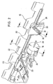
- Fig. 1 13 is a schematic perspective view, seen obliquely from the front, of a wind deflector 10 and the front, transversal part of a roof roof 12 for a vehicle roof, the vehicle roof having a roof opening (not shown), which is supported by an adjustable closing element (not shown). optionally closed or at least partially exposed.
- the wind deflector 10 and the part of the roof frame 12 shown are arranged in the region of the front edge of the roof opening, wherein the Roof frame serves as a storage for the closing element.
- the deflector extends over the entire width of the roof opening.
- the closing element may be, for example, the cover of a sliding roof, sliding roof, externally guided sliding roof or spoiler roof or the slats of a slatted roof.
- the wind deflector 10 includes a front Windabweiser nature and two lateral arms 14 which are pivotally mounted at its rear end at 16 about a extending in the roof transverse direction fixed axis.
- the wind deflector 10 is biased in the manner of known manner by means of a spring element in a fully flared position in which the front Windabweiser construction is issued above the fixed roof surface to Windund Wummer noises when driving with open Closing element occur to eliminate or reduce.
- closing the closing element of the wind deflector is pressed against the spring bias with its front surface down in a trained in the roof frame storage space or lowered, this is done by operating the lateral arms 14 when closing the closing element.
- the fully deployed position of the wind deflector 10 is predetermined by a fixed stop (not shown). In general, however, it is desirable under some circumstances to adjust the wind deflector 10 also in intermediate positions between the lowered and fully deployed positions. Thus, noisy noises mainly occur in a lower speed range (for example, up to 100 km / h), so that in this range usually the fully deployed position of the wind deflector 10 is desirable, while at higher speeds barely whining noises occur, so that in this Speed range is not required to fully expose the deflector.
- an adjusting device described below which has a servomotor 18, which may be designed, for example, as a rotary motor, which can be adjusted in the transverse roof direction Spindle 20 drives, and a rod-like extending in the roof transverse direction zugtiksteifes element 22, which is driven by a coupling assembly 24 from the spindle 20 to a sliding movement in the roof transverse direction and on a guide rail 23 which is formed on the roof frame 12 and provided with a cover 25 , slidably guided in roof transverse direction.
- a servomotor 18 which may be designed, for example, as a rotary motor, which can be adjusted in the transverse roof direction Spindle 20 drives, and a rod-like extending in the roof transverse direction zugdrucksteifes element 22, which is driven by a coupling assembly 24 from the spindle 20 to a sliding movement in the roof transverse direction and on a guide rail 23 which is formed on the roof frame 12 and provided with a cover 25 , slidably guided in roof transverse
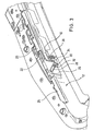
- the adjusting device further comprises a guide element formed as a link element 26, which forms part of the tension-pressure-resistant element 22 or is fixedly connected thereto and has an inclined link slot 28, in which engages an engagement element designed as a link pin or bolt 30, see in particular Fig. 2 ,
- the guide pin 30 is further guided in a in the roof vertical direction, ie substantially perpendicular to the direction of movement of the link element 26 and formed in the roof frame 12 slide track 32 that it only perpendicular to the direction of movement of the link element 26 (ie in the example shown only in FIG the roof upward direction) is displaceable, see FIGS. 2 . 3 .
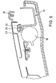
- the guide pin 30 is connected at its rear by means of a flexible member 34, which may be formed, for example, as a band, with a hold-down 36, which is in firm engagement with the wind deflector 10, see in particular Fig. 5 ,
- the servomotor can also be designed as a linear motor.
- the adjusting device for the wind deflector 10 will be explained in more detail. If, for example, a lowering of the wind deflector 10 starting from the fully deployed position is desired when the closing element is open, for example, because a predetermined speed threshold is exceeded, the servo motor is correspondingly driven to a rotational movement, which causes a displacement of the spindle 20 in the roof transverse direction.
- the control of the servomotor 18 could, for example, also take place as a function of the degree of opening of the closing element.
- the flexible element 34 ensures a karsteife, but not for a pressure-resistant connection between the guide pin 30 and the hold-down 36.
- the wind deflector can be brought by means of the servomotor 18 in the fully lowered position, as this usually occurs anyway when closing the closing element by actuation of the lateral arms 14 (in such a case, a flexibility of the connecting element 34 required).
- Fig. 1 is provided in a symmetrical arrangement in the vicinity of the lateral edge respectively on both sides of one of the link elements 26, which are driven jointly by the servo motor 18, whereby each of the hold-36 engages spaced at roof transverse direction points.
- the entire adjusting device is arranged in the region of the front part of the roof frame 12 and at least partially integrated in this.
- the roof frame acts as a body-mounted support for the adjusting device.
- the wind deflector 10 may instead of in Fig. 1 embodiment shown with two lateral arms 14 may alternatively be formed as Windabweiserlamelle which is rotatable about a extending in the roof transverse direction at or near the front end of the Windabweiserlamelle axis of rotation with its trailing edge.
- the hold-down expediently engage in the vicinity of the trailing edge of the wind deflector blade in order to lower it in intermediate positions.
- the displaceable in the roof transverse direction guide element in the example shown, the link element 26
- the engagement element in particular as a guide pin is formed while in the roof top direction displaceable element (in the example shown, the guide pin 30) is provided with an inclined slide track or track, with which the engagement member is slidably engaged.
- the guideway does not necessarily have to be formed as a slotted slot, but also in other ways, for example, as a guide bar, may be formed, wherein the engagement member does not necessarily have to be designed as a guide pin, but for example as the guide bar encompassing shoe formed can be.
- the adjusting mechanism shown could be used not only for lowering the wind deflector, but also for issuing the same, in which case the connection between the engagement member and the hold-down not only zugsteif, but should also be designed to be pressure-resistant. In this case, then the adjusting mechanism could in principle be used to reach the end positions of the wind deflector.
Abstract
Description
Die vorliegende Erfindung betrifft ein Fahrzeugdach mit einer Dachöffnung und einem Windabweiser gemäß dem Oberbegriff von Anspruch 1.The present invention relates to a vehicle roof with a roof opening and a wind deflector according to the preamble of claim 1.
Es sind gattungsgemäße Fahrzeugdächer bekannt, bei welchen der Windabweiser um eine in Dachquerrichtung verlaufende dachfeste Achse schwenkbar gelagert und in Richtung der voll ausgestellten Position federnd vorgespannt ist, wobei der Windabweiser beim Schließen des Schließelements bzw. des Deckels mittels des Deckelantriebs gegen die Vorspannkraft abgesenkt wird, und wobei der an dem Windabweiser angreifende Halter in den Zwischenpositionen als Niederhalter wirkt.Generic vehicle roofs are known, in which the wind deflector is mounted pivotably about a roof-mounted roof axis extending axis and resiliently biased towards the fully deployed position, the wind deflector is lowered when closing the closing element or the lid by means of the cover drive against the biasing force, and wherein the holder acting on the wind deflector acts as a hold-down in the intermediate positions.
Ein solches gattungsgemäßes Fahrzeugdach ist beispielsweise in der
Aus der
In der
In der
In der
In der
In der
Die oben erwähnten Fahrzeugdächer weisen verschiedene Nachteile auf. Sie erlauben z.T. keine von Deckel unabhängige Betätigung des Windabweisers und die Stellvorrichtung des Windabweisers benötigt viel Bauraum oder gewährleistet keine zuverlässige Steuerung des Windabweisers oder benötigt relativ viele Bauteile.The vehicle roofs mentioned above have various disadvantages. They allow z.T. no independent of lid actuation of the wind deflector and the actuator of the wind deflector requires a lot of space or does not provide reliable control of the wind deflector or requires a relatively large number of components.
Es ist Aufgabe der vorliegenden Erfindung, ein Fahrzeugdach mit einer Dachöffnung und einen Windabweiser zu schaffen, wobei eine möglichst flexible Einstellung von Zwischenpositionen des Windabweisers möglich sein soll, der Bauraumbedarf sowie die Zahl der benötigten Teile möglichst gering gehalten werden soll und ein robuster Aufbau ermöglicht werden soll.It is an object of the present invention to provide a vehicle roof with a roof opening and a wind deflector, with a flexible setting of intermediate positions of the wind deflector should be possible, the space requirements and the number of parts needed to be kept as low as possible and a robust design should.
Diese Aufgabe wird erfindungsgemäß gelöst durch ein Fahrzeugdach gemäß Anspruch 1 bzw. 27, wobei die Lösung gemäß Anspruch 27 eine kinematische Umkehr bezüglich der Lösung gemäß Anspruch 1 darstellt.This object is achieved by a vehicle roof according to claim 1 or 27, wherein the solution according to claim 27 represents a kinematic reversal with respect to the solution according to claim 1.
Bei der erfindungsgemäßen Lösung ist vorteilhaft, dass mittels der Stellvorrichtung auf einfache Weise die Position des Windabweisers, beispielsweise in Abhängigkeit von der Fahrtgeschwindigkeit und/oder dem Öffnungsgrad des Schließelements, variiert werden kann, um eine optimale Reduzierung von Wind- und Wummer-Geräuschen zu erzielen, wobei die Stellvorrichtung sehr kompakt mit geringem Bauraumbedarf gestaltet werden kann und dabei insbesondere in dem vorderen quer verlaufenden Teil eines Dachrahmens für das Schließelement integriert werden kann, wobei ferner die Zahl der zusätzlichen, für die Stellvorrichtung erforderlichen Teile sehr gering gehalten werden kann und wobei die Stellvorrichtung sehr robust und damit zuverlässig ausgebildet werden kann.In the solution according to the invention is advantageous that by means of the adjusting device in a simple manner, the position of the wind deflector, for example, depending on the driving speed and / or the degree of opening of the closing element, can be varied in order to achieve an optimal reduction of wind and Wummer noises wherein the adjusting device can be designed very compact with low space requirements and can be integrated in particular in the front transverse part of a roof frame for the closing element, further wherein the number of additional parts required for the adjusting device can be kept very low and wherein the Adjusting device can be made very robust and thus reliable.
Bevorzugte Ausgestaltungen der Erfindung ergeben sich aus den Unteransprüchen.Preferred embodiments of the invention will become apparent from the dependent claims.
Im folgenden wird die Erfindung anhand der beigefügten Zeichnungen beispielhaft näher erläutert. Dabei zeigen:
-
Fig. 1 eine schematische perspektivische Ansicht eines erfindungsgemäßen Fahrzeugdaches, wobei lediglich der Windabweiser und der vordere Dachrahmenbereich, gesehen von schräg vorn, dargestellt sind, -
Fig. 2 eine vergrößerte Ansicht eines Teilbereichs des Fahrzeugdaches vonFig. 1 , wobei der Dachrahmen zum Teil frei geschnitten ist und der Windabweiser in einer abgesenkten Position dargestellt ist; -
Fig. 3 eine schematische perspektivische Ansicht des Bereichs vonFig. 2 , wobei dieser inFig. 3 jedoch von schräg hinten gesehen ist und der Windabweiser zum Teil weggeschnitten ist; -
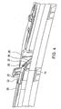
Fig. 4 eine Ansicht ähnlich zuFig. 3 , jedoch aus einer etwas anderen Perspektive, wobei die Stellvorrichtung für den Windabweiser in einer Position dargestellt ist, bei welcher der Windabweiser voll ausgestellt ist; -
Fig. 5 eine Schnittdarstellung in Dachlängsrichtung im Bereich der Linie V-V vonFig. 2 , wobei jedoch der Kulissenstift, im Gegensatz zuFig. 2 , in seiner oberen Stellung gezeigt ist; -
Fig. 6 eine Schnittdarstellung entlang der Linie VI-VI vonFig. 2 ; und -
Fig. 7 eine Ansicht ähnlich zuFig. 3 , wobei ein Teil des Kulissenelements weggeschnitten ist und die Stellvorrichtung in einer Position dargestellt ist, in welcher der Windabweiser voll ausgestellt ist.
-
Fig. 1 a schematic perspective view of a vehicle roof according to the invention, wherein only the wind deflector and the front roof frame area, as seen from obliquely forward, are shown, -
Fig. 2 an enlarged view of a portion of the vehicle roof ofFig. 1 wherein the roof frame is partially cut free and the wind deflector is shown in a lowered position; -
Fig. 3 a schematic perspective view of the range ofFig. 2 , this one inFig. 3 but seen from diagonally behind and the wind deflector is partially cut away; -
Fig. 4 a view similar toFig. 3 but from a slightly different perspective, the wind deflector actuator being shown in a position where the wind deflector is fully deployed; -
Fig. 5 a sectional view in the roof longitudinal direction in the area of the line VV ofFig. 2 , however, the guide pin, as opposed toFig. 2 , shown in its upper position; -
Fig. 6 a sectional view taken along the line VI-VI ofFig. 2 ; and -
Fig. 7 a view similar toFig. 3 , wherein a part of the link element is cut away and the adjusting device is shown in a position in which the wind deflector is fully exposed.
In
Bei dem Schließelement kann es sich beispielsweise um den Deckel eines Schiebedaches, Schiebehebedaches, außengeführten Schiebedaches oder Spoilerdaches oder um die Lamellen eines Lamellendaches handeln.The closing element may be, for example, the cover of a sliding roof, sliding roof, externally guided sliding roof or spoiler roof or the slats of a slatted roof.
Der Windabweiser 10 umfaßt eine vordere Windabweiserfläche und zwei seitliche Arme 14, die an ihrem hinteren Ende bei 16 um eine in Dachquerrichtung verlaufende feste Achse schwenkbar gelagert sind. Der Windabweiser 10 ist im Bereich der seitlichen Arme 14 in an sich bekannter Weise mittels eines Federelements in eine voll ausgestellte Position vorgespannt, in welcher die vordere Windabweiserfläche nach oben über die feste Dachfläche ausgestellt ist, um Windund Wummer-Geräusche, die im Fahrbetrieb bei geöffnetem Schließelement auftreten, zu eliminieren bzw. zu verringern. Beim Schließen des Schließelements wird der Windabweiser entgegen der Federvorspannung mit seiner vorderen Fläche nach unten in einen in dem Dachrahmen ausgebildeten Ablageraum gedrückt bzw. abgesenkt, wobei dies durch Betätigung der seitlichen Arme 14 beim Schließen des Schließelements erfolgt.The
Die voll ausgestellte Position des Windabweisers 10 wird durch einen festen Anschlag (nicht gezeigt) vorgegeben. In der Regel ist es jedoch wünschenswert, unter bestimmten Umständen den Windabweiser 10 auch in Zwischenpositionen zwischen der abgesenkten und der voll ausgestellten Position einzustellen. So treten üblicherweise Wummergeräusche hauptsächlich in einem niedrigeren Geschwindigkeitsbereich (beispielsweise bis 100 km/h) auf, so dass in diesem Bereich in der Regel die voll ausgestellte Position des Windabweisers 10 wünschenswert ist, während bei höheren Geschwindigkeiten kaum Wummergeräusche auftreten, so dass es in diesem Geschwindigkeitsbereich nicht erforderlich ist, den Windabweiser voll auszustellen.The fully deployed position of the
Zum Realisieren solcher Zwischenpositionen ist eine nachfolgend beschriebene Stellvorrichtung vorgesehen, welche einen Stellmotor 18, der beispielsweise als Rotationsmotor ausgebildet sein kann, der eine in Dachquerrichtung verstellbare Spindel 20 antreibt, und ein gestängeartig in Dachquerrichtung verlaufendes zugdrucksteifes Element 22, aufweist welches mittels einer Kupplungsanordnung 24 von der Spindel 20 zu einer Verschiebebewegung in Dachquerrichtung angetrieben ist und an einer Führungsschiene 23, die an dem Dachrahmen 12 ausgebildet und mit einer Abdeckung 25 versehen ist, in Dachquerrichtung verschiebbar geführt ist. Die Stellvorrichtung umfasst ferner ein als Kulissenelement 26 ausgebildetes Führungselement, welches einen Teil des zug-drucksteifen Elements 22 bildet oder mit diesem fest verbunden ist und einen geneigten Kulissenschlitz 28 aufweist, in welchen ein als Kulissenstift bzw. -bolzen 30 ausgebildetes Eingriffselement eingreift, siehe insbesondere
Statt als Rotationsmotor mit nachgeschalteter Anordnung zum Umsetzen einer Drehbewegung in eine Linearbewegung ausgebildet zu sein, kann der Stellmotor auch als Linearmotor ausgebildet sein.Instead of being designed as a rotary motor with a downstream arrangement for converting a rotational movement into a linear movement, the servomotor can also be designed as a linear motor.
Im folgenden soll die Funktionsweise der Stellvorrichtung für den Windabweiser 10 näher erläutert werden. Falls beispielsweise ein Absenken des Windabweisers 10 ausgehend aus der voll ausgestellten Position bei geöffnetem Schließelement gewünscht wird, beispielsweise weil eine vorgegebene Geschwindigkeitsschwelle überschritten wird, wird der Stellmotor entsprechend zu einer Drehbewegung angesteuert, welche eine Verschiebung der Spindel 20 in der Dachquerrichtung bewirkt. Zusätzlich oder alternativ zu einer fahrtgeschwindigkeitsabhängigen Steuerung könnte die Steuerung des Stellmotors 18 beispielsweise auch in Abhängigkeit von dem Öffnungsgrad des Schließelements erfolgen. Über das Kupplungselement 24 wird die Verschiebebewegung der Spindel 20 in eine entsprechende Verschiebebewegung des zug-drucksteifen Elements 22 in der Dachquerrichtung umgesetzt, wobei auch das Kulissenelement 26 entsprechend in der Dachquerrichtung verschoben wird. Aufgrund des Eingriffs des Kulissenstifts 30 in die Kulissenbahn 28 und der Neigung der Kulissenbahn 28 (die im gezeigten Beispiel als gerade Bahn mit gleichmäßiger Steigung ausgebildet ist) erfolgt, je nach Drehrichtung des Motors 18, ein Absenken oder ein Anheben des Kulissenstifts 30, wobei sich dieser in der dachrahmenfesten Führungs- bzw. Kulissenbahn 32 nach unten bzw. nach oben bewegt. In
Das flexible Element 34 sorgt für eine zugsteife, jedoch nicht für eine drucksteife Verbindung zwischen dem Kulissenstift 30 und dem Niederhalter 36. Wenn sich der Kulissenstift 30 aufgrund der Verschiebeewegung des Kulissenelements 26 in der dachrahmenfesten Führungsbahn 32 nach unten bewegt, wird entsprechend mittels der zugsteifen Koppelung über das flexible Element 34 auch der Niederhalter 36, und damit der Windabweiser 10, um eine entsprechende Strecke nach unten gezogen, wobei dabei die Federvorspannung des Windabweisers 10 überwunden wird. Auf diese Weise kann der Windabweiser 10 mittels des Stellmotors 18 ausgehend von der voll ausgestellten Position wahlweise in Zwischenpositionen abgesenkt werden. Es ist dabei jedoch nicht erforderlich, dass der Windabweiser mittels des Stellmotors 18 in die voll abgesenkte Position gebracht werden kann, da dies in der Regel ohnehin beim Schließen des Schließelements durch Betätigung der seitlichen Arme 14 erfolgt (in einem solchen Fall ist eine Flexibilität des Verbindungselements 34 erforderlich).The
Gemäß
Vorzugsweise ist die gesamte Stellvorrichtung im Bereich des vorderen Teils des Dachrahmens 12 angeordnet und mindestens zum Teil in diesen integriert. Der Dachrahmen wirkt als karosseriefester Träger für die Stellvorrichtung.Preferably, the entire adjusting device is arranged in the region of the front part of the
Der Windabweiser 10 kann statt der in
Ferner ist auch eine kinematische Umkehr der bisher beschriebenen Stellmechanik vorstellbar, wobei dann das in Dachquerrichtung verschiebbare Führungselement (im gezeigten Beispiel das Kulissenelement 26) nicht mit einer Kulissenbahn versehen ist, sondern als Eingriffselement, insbesondere als Kulissenstift, ausgebildet ist, während das in der Dachhochrichtung verschiebbare Element (im gezeigten Beispiel der Kulissenstift 30) mit einer geneigten Kulissenbahn bzw. Führungsbahn versehen ist, mit welcher das Eingriffselement verschiebbar in Eingriff steht.Furthermore, a kinematic reversal of the previously described adjusting mechanism is conceivable, in which case the displaceable in the roof transverse direction guide element (in the example shown, the link element 26) is not provided with a slide track, but as an engagement element, in particular as a guide pin is formed while in the roof top direction displaceable element (in the example shown, the guide pin 30) is provided with an inclined slide track or track, with which the engagement member is slidably engaged.
Es versteht sich, dass die Führungsbahn nicht notwendigerweise als Kulissenschlitz ausgebildet sein muß, sondern auch in anderer Weise, beispielsweise als Führungssteg, ausgebildet sein kann, wobei auch das Eingriffselement entsprechend nicht notwendigerweise als Kulissenstift ausgebildet sein muss, sondern beispielsweise als den Führungssteg umgreifender Gleitschuh ausgebildet sein kann.It is understood that the guideway does not necessarily have to be formed as a slotted slot, but also in other ways, for example, as a guide bar, may be formed, wherein the engagement member does not necessarily have to be designed as a guide pin, but for example as the guide bar encompassing shoe formed can be.
Ferner sei noch erwähnt, dass die gezeigte Stellmechanik nicht nur zum Absenken des Windabweisers, sondern auch zum Ausstellen desselben verwendet werden könnte, wobei in diesem Fall dann die Verbindung zwischen dem Eingriffselement und dem Niederhalter nicht nur zugsteif, sondern auch drucksteif ausgebildet sein müßte. In diesem Fall könnte dann die Stellmechanik grundsätzlich auch zum Erreichen der Endpositionen des Windabweisers verwendet werden.Furthermore, it should be mentioned that the adjusting mechanism shown could be used not only for lowering the wind deflector, but also for issuing the same, in which case the connection between the engagement member and the hold-down not only zugsteif, but should also be designed to be pressure-resistant. In this case, then the adjusting mechanism could in principle be used to reach the end positions of the wind deflector.
- 1010
- Windabweiserwind deflector
- 1212
- Dachrahmenroof frame
- 1414
- seitliche Arme von 10lateral arms of 10
- 1616
- Schwenkpunkte von 10Pivot points of 10
- 1818
- Motorengine
- 2020
- Spindelspindle
- 2222
- zug-/drucksteifes Antriebselement für 26tension- / compression-resistant drive element for 26
- 2323
- Führungsschiene für 22Guide rail for 22
- 2424
- Kupplungclutch
- 2626
- Kulissenelementlink element
- 2828
- Kulissenschlitzlink slot
- 3030
- Kulissenstiftlink pin
- 3232
- dachrahmenfeste Führung für 30roof frame fixed guide for 30
- 3434
- flexible Verbindung von 30 und 36flexible connection of 30 and 36
- 3636
- NiederhalterStripper plate
Claims (27)
- Vehicle roof with a roof opening, a closing element which can be displaced in order to optionally close or at least partially open up the roof opening, a wind deflector (10) which is arranged in the region of the front edge of the roof opening and can be displaced between a lowered and a completely deployed position, and with an adjusting device (18, 20, 22, 26, 30) for setting intermediate positions of the wind deflector, said adjusting device having a holder (36) which acts on the wind deflector and an adjustment mechanism (22, 26, 30) which is driven by a drive (18, 20) and by means of which the holder can be displaced vertically to provide intermediate positions of the wind deflector, characterized in that the adjustment mechanism has a guide element (26) which is driven by the drive so as to move along the wind deflector and has an inclined guide track (28) along which an engagement element (30) which is connected to the holder (36), is displaceably guided, wherein the engagement element is mounted in such a manner on a support (12, 32) mounted on the vehicle body that it can be displaced with respect to the support only perpendicularly to the direction of movement of the guide element.
- Vehicle roof according to Claim 1, characterized in that the guide track is designed as a slideway (28).
- Vehicle roof according to Claim 2, characterized in that the slideway is designed as a sliding slot (28) and the engagement element is designed as a sliding pin (30) which is guided in the sliding slot.
- Vehicle roof according to Claim 2 or 3, characterized in that the engagement element (30) is guided displaceably on the support (12) mounted on the vehicle body, in a slideway running in the vertical direction of the roof.
- Vehicle roof according to one of the preceding claims, characterized in that the guide element (26) is driven so as to move along the front region of the wind deflector (10) in the transverse direction of the roof.
- Vehicle roof according to one of the preceding claims, characterized in that the wind deflector (10) is prestressed towards the fully deployed position.
- Vehicle roof according to Claim 6, characterized in that the wind deflector (10) is lowered counter to the prestressing force by closing of the closing element.
- Vehicle roof according to Claim 6 or 7, characterized in that the holder for providing the intermediate positions of the wind deflector (10) acts counter to the prestressing force as a holding-down device (36).
- Vehicle roof according to Claim 8, characterized in that the holder (36) is connected to the engagement element (30) by means of a flexible element (34).
- Vehicle roof according to Claim 9, characterized in that the flexible element (34) is designed as a tension-resistant, but not compression-resistant, connection, in particular as a strap.
- Vehicle roof according to one of the preceding claims, characterized in that the wind deflector (10) extends over the entire width of the roof opening.
- Vehicle roof according to one of the preceding claims, characterized in that the wind deflector (10) can be pivoted about an axis which runs in the transverse direction of the roof and is mounted on the vehicle body.
- Vehicle roof according to Claim 12, characterized in that the pivot axis lies at the rear end (16) of the wind deflector (10).
- Vehicle roof according to one of the preceding claims, characterized in that the guide element (26) is connected to the drive (18, 20) by means of a tension-and compression-resistant element (22) which is guided along a guide (23) formed on the support (12) mounted on the vehicle body.
- Vehicle roof according to Claim 14, characterized in that the guide element (26) is formed integrally with the tension- and compression-resistant element (22).
- Vehicle roof according to one of the preceding claims, characterized in that the drive has a servomotor which is designed as a linear motor or as a rotation motor (18) with an arrangement (20) connected downstream for the conversion of a rotational movement into a linear movement.
- Vehicle roof according to Claim 16, characterized in that the drive is formed by a spindle (20) driven by a rotation motor (18).
- Vehicle roof according to Claim 17, characterized in that the spindle (20) is connected to the tension-and compression-resistant element (22) by means of a coupling element (24).
- Vehicle roof according to one of the preceding claims, characterized in that the drive (18, 20) is activated as a function of the travel speed and/or the degree of opening of the closing element.
- Vehicle roof according to one of the preceding claims, characterized in that at least two of the adjustment mechanisms (26, 30) and two of the holders (36) are provided, with the adjustment mechanisms being driven by a common drive (18, 20).
- Vehicle roof according to Claim 20, characterized in that the holders (36) act on points of the wind deflector (10) that are spaced apart in the transverse direction of the roof, in particular in each case in the lateral edge region.
- Vehicle roof according to one of the preceding claims, characterized in that the entire adjusting device (18, 20, 22, 26, 30) is arranged in the region of the front edge of the roof opening.
- Vehicle roof according to Claim 22, characterized in that the support mounted on the vehicle body is the front section, which runs in the transverse direction of the roof, of a frame (12) arranged below the roof opening.
- Vehicle roof according to Claim 23, characterized in that the adjusting device (20, 22, 26, 30) is at least partially integrated in the support mounted on the vehicle body.
- Vehicle roof according to one of the preceding claims, characterized in that the closing element is designed as a cover, in particular of a sliding roof, tilt-and-slide roof, externally guided sliding roof or spoiler roof, or as a lamellar roof.
- Vehicle roof according to Claim 12, characterized in that the wind deflector is designed as a wind deflector slat which can be deployed at its rear edge.
- Vehicle roof with a roof opening, a closing element which can be displaced in order to optionally close or at least partially open up the roof opening, a wind deflector (10) which is arranged in the region of the front edge of the roof opening and can be displaced between a lowered and a completely deployed position, and with an adjusting device (18, 20, 22, 26, 30) for setting intermediate positions of the wind deflector, said adjusting device having a holder (36) which acts on the wind deflector and an adjustment mechanism (22, 26, 30) which is driven by a drive (18, 20) and by means of which the holder can be displaced vertically to provide intermediate positions of the wind deflector, characterized in that the adjustment mechanism has an engagement element which is driven by the drive so as to move along the wind deflector and is in engagement in a displaceable manner with an inclined guide track of a guide element connected fixedly to the holder, the guide element being mounted in such a manner on a support mounted on the vehicle body that it can be displaced with respect to the support only perpendicularly to the direction of movement of the engagement element.
Applications Claiming Priority (2)
| Application Number | Priority Date | Filing Date | Title |
|---|---|---|---|
| DE10344884 | 2003-09-26 | ||
| DE10344884A DE10344884B3 (en) | 2003-09-26 | 2003-09-26 | Vehicle roof with a roof opening and a wind deflector |
Publications (3)
| Publication Number | Publication Date |
|---|---|
| EP1518733A2 EP1518733A2 (en) | 2005-03-30 |
| EP1518733A3 EP1518733A3 (en) | 2007-03-21 |
| EP1518733B1 true EP1518733B1 (en) | 2008-09-10 |
Family
ID=34177982
Family Applications (1)
| Application Number | Title | Priority Date | Filing Date |
|---|---|---|---|
| EP04022662A Not-in-force EP1518733B1 (en) | 2003-09-26 | 2004-09-23 | Vehicle roof with roof opening and wind deflector |
Country Status (4)
| Country | Link |
|---|---|
| US (2) | US7093892B2 (en) |
| EP (1) | EP1518733B1 (en) |
| AT (1) | ATE407824T1 (en) |
| DE (2) | DE10344884B3 (en) |
Families Citing this family (5)
| Publication number | Priority date | Publication date | Assignee | Title |
|---|---|---|---|---|
| DE102008036887B4 (en) | 2008-08-07 | 2010-05-06 | Daimler Ag | Wind deflector with linearly oscillating deflector element |
| JP5446231B2 (en) * | 2008-12-05 | 2014-03-19 | アイシン精機株式会社 | Sunroof device |
| US9586464B2 (en) * | 2015-03-31 | 2017-03-07 | Nissan North America, Inc. | Vehicle sunroof wind deflector |
| US10583725B1 (en) * | 2018-09-28 | 2020-03-10 | Nissan North America, Inc. | Vehicle wind deflector assembly |
| US11685243B2 (en) * | 2021-06-10 | 2023-06-27 | Inalfa Roof Systems Group B.V. | Net wind deflector with folding anti buffeting flap |
Family Cites Families (14)
| Publication number | Priority date | Publication date | Assignee | Title |
|---|---|---|---|---|
| DE3913567A1 (en) * | 1989-04-25 | 1990-10-31 | Weinsberg Karosseriewerke | Car sliding-roof wind deflector - has additional guide members sliding on and parallel to it |
| DE3922874A1 (en) * | 1989-07-12 | 1991-01-24 | Webasto Ag Fahrzeugtechnik | Wind deflector along front edge sunroof - has deflector actuating lever guided and pivoting in vertical track |
| DE19701479A1 (en) * | 1997-01-17 | 1998-07-23 | Bayerische Motoren Werke Ag | Wind deflector operating device for motor vehicle roof |
| DE19714492B4 (en) * | 1997-04-08 | 2008-11-20 | Bayerische Motoren Werke Aktiengesellschaft | Actuating device for a wind deflector on a vehicle sunroof |
| DE19802301A1 (en) * | 1998-01-22 | 1999-07-29 | Bosch Gmbh Robert | Wind deflector for a motor vehicle equipped with a sunroof |
| DE19809943C5 (en) * | 1998-03-07 | 2006-01-05 | Webasto Ag | Vehicle wind deflector with adjustable installation speed depending on the vehicle speed |
| DE19958742B4 (en) * | 1999-12-07 | 2004-12-09 | Webasto Vehicle Systems International Gmbh | Device for influencing the air flow |
| FR2810592B1 (en) * | 2000-06-27 | 2002-11-29 | Webasto Systemes Carrosserie | SUNROOF DEFLECTOR SYSTEM |
| DE10146285B4 (en) * | 2001-03-19 | 2007-03-29 | Webasto Ag | vehicle roof |
| DE10137650A1 (en) * | 2001-08-03 | 2003-02-27 | Webasto Vehicle Sys Int Gmbh | Wind deflector for motor vehicle roof has common driven control element for deflector body adjusting levers |
| DE10142047A1 (en) * | 2001-08-28 | 2003-03-20 | Arvinmeritor Gmbh | Wind deflector with actuator for a sliding roof system |
| DE10210617C1 (en) * | 2002-03-11 | 2003-12-04 | Webasto Vehicle Sys Int Gmbh | Opening automobile roof provided with pivoted wind deflector at front edge of roof opening and associated setting device |
| JP4235402B2 (en) * | 2002-05-30 | 2009-03-11 | アイシン精機株式会社 | Sunroof device |
| DE102004042810A1 (en) * | 2004-09-03 | 2006-03-09 | Arvinmeritor Gmbh | sliding roof system |
-
2003
- 2003-09-26 DE DE10344884A patent/DE10344884B3/en not_active Expired - Fee Related
-
2004
- 2004-09-23 AT AT04022662T patent/ATE407824T1/en not_active IP Right Cessation
- 2004-09-23 EP EP04022662A patent/EP1518733B1/en not_active Not-in-force
- 2004-09-23 DE DE502004008011T patent/DE502004008011D1/en active Active
- 2004-09-27 US US10/949,809 patent/US7093892B2/en active Active
-
2006
- 2006-08-22 US US11/466,165 patent/US7404600B2/en active Active
Also Published As
| Publication number | Publication date |
|---|---|
| US20050093344A1 (en) | 2005-05-05 |
| DE10344884B3 (en) | 2005-05-25 |
| ATE407824T1 (en) | 2008-09-15 |
| DE502004008011D1 (en) | 2008-10-23 |
| US7404600B2 (en) | 2008-07-29 |
| US7093892B2 (en) | 2006-08-22 |
| EP1518733A3 (en) | 2007-03-21 |
| EP1518733A2 (en) | 2005-03-30 |
| US20070040417A1 (en) | 2007-02-22 |
Similar Documents
| Publication | Publication Date | Title |
|---|---|---|
| DE102006002064B4 (en) | Vehicle roof with a sliding above a fixed roof section lid | |
| EP2451665B2 (en) | Sliding roof device, in particular for a motor vehicle | |
| DE3442631A1 (en) | SLIDING LIFTING ROOF | |
| DE69915122T2 (en) | CONSTRUCTION OF AN OPENING VEHICLE ROOF | |
| EP1745965A2 (en) | Sunroof wind deflector | |
| DE102006051109B4 (en) | Vehicle roof with a movable roof part | |
| EP0720927B1 (en) | Vehicle roof provided with a roof panel opened by tilting | |
| WO2009152789A1 (en) | Vehicle roof having sunroof guided on the outside | |
| DE10329536B4 (en) | vehicle roof | |
| EP1518733B1 (en) | Vehicle roof with roof opening and wind deflector | |
| DE19809943C5 (en) | Vehicle wind deflector with adjustable installation speed depending on the vehicle speed | |
| DE10246753B4 (en) | vehicle roof | |
| DE60009784T2 (en) | Construction of an openable vehicle roof | |
| DE202007001217U1 (en) | Automotive roof has fixed rear panel and front panel that slides through side guides | |
| WO2015022131A1 (en) | Wind deflector having an extension mechanism | |
| EP0551840B1 (en) | Sliding sunroof for motorvehicle | |
| DE10110014B4 (en) | Drive arrangement for a pivotable for storage in a storage space in a vehicle element of a vehicle roof | |
| DE10226110B4 (en) | vehicle roof | |
| EP0551841A1 (en) | Locking device for sliding-lifting roofs for motor vehicles | |
| DE19907806C2 (en) | Openable vehicle roof with extendable wind deflector | |
| DE10137801B4 (en) | Wind deflector for a vehicle roof | |
| DE102009042953B4 (en) | Wind deflector arrangement for a vehicle roof | |
| DE19719644A1 (en) | Vehicle roof wind deflector | |
| DE102005037703A1 (en) | Sunroof for vehicle, comprises front segment to be slid across rear segment while lifted using stepped guide unit and locking element | |
| EP1838544B1 (en) | Vehicle roof |
Legal Events
| Date | Code | Title | Description |
|---|---|---|---|
| PUAI | Public reference made under article 153(3) epc to a published international application that has entered the european phase |
Free format text: ORIGINAL CODE: 0009012 |
|
| AK | Designated contracting states |
Kind code of ref document: A2 Designated state(s): AT BE BG CH CY CZ DE DK EE ES FI FR GB GR HU IE IT LI LU MC NL PL PT RO SE SI SK TR |
|
| AX | Request for extension of the european patent |
Extension state: AL HR LT LV MK |
|
| PUAL | Search report despatched |
Free format text: ORIGINAL CODE: 0009013 |
|
| AK | Designated contracting states |
Kind code of ref document: A3 Designated state(s): AT BE BG CH CY CZ DE DK EE ES FI FR GB GR HU IE IT LI LU MC NL PL PT RO SE SI SK TR |
|
| AX | Request for extension of the european patent |
Extension state: AL HR LT LV MK |
|
| 17P | Request for examination filed |
Effective date: 20070921 |
|
| AKX | Designation fees paid |
Designated state(s): AT BE BG CH CY CZ DE DK EE ES FI FR GB GR HU IE IT LI LU MC NL PL PT RO SE SI SK TR |
|
| GRAP | Despatch of communication of intention to grant a patent |
Free format text: ORIGINAL CODE: EPIDOSNIGR1 |
|
| GRAS | Grant fee paid |
Free format text: ORIGINAL CODE: EPIDOSNIGR3 |
|
| GRAA | (expected) grant |
Free format text: ORIGINAL CODE: 0009210 |
|
| AK | Designated contracting states |
Kind code of ref document: B1 Designated state(s): AT BE BG CH CY CZ DE DK EE ES FI FR GB GR HU IE IT LI LU MC NL PL PT RO SE SI SK TR |
|
| REG | Reference to a national code |
Ref country code: GB Ref legal event code: FG4D Free format text: NOT ENGLISH |
|
| REG | Reference to a national code |
Ref country code: CH Ref legal event code: EP |
|
| REG | Reference to a national code |
Ref country code: IE Ref legal event code: FG4D Free format text: LANGUAGE OF EP DOCUMENT: GERMAN |
|
| REF | Corresponds to: |
Ref document number: 502004008011 Country of ref document: DE Date of ref document: 20081023 Kind code of ref document: P |
|
| PG25 | Lapsed in a contracting state [announced via postgrant information from national office to epo] |
Ref country code: SI Free format text: LAPSE BECAUSE OF FAILURE TO SUBMIT A TRANSLATION OF THE DESCRIPTION OR TO PAY THE FEE WITHIN THE PRESCRIBED TIME-LIMIT Effective date: 20080910 Ref country code: FI Free format text: LAPSE BECAUSE OF FAILURE TO SUBMIT A TRANSLATION OF THE DESCRIPTION OR TO PAY THE FEE WITHIN THE PRESCRIBED TIME-LIMIT Effective date: 20080910 |
|
| BERE | Be: lapsed |
Owner name: WEBASTO A.G. Effective date: 20080930 |
|
| REG | Reference to a national code |
Ref country code: IE Ref legal event code: FD4D |
|
| PG25 | Lapsed in a contracting state [announced via postgrant information from national office to epo] |
Ref country code: IE Free format text: LAPSE BECAUSE OF FAILURE TO SUBMIT A TRANSLATION OF THE DESCRIPTION OR TO PAY THE FEE WITHIN THE PRESCRIBED TIME-LIMIT Effective date: 20080910 Ref country code: BG Free format text: LAPSE BECAUSE OF FAILURE TO SUBMIT A TRANSLATION OF THE DESCRIPTION OR TO PAY THE FEE WITHIN THE PRESCRIBED TIME-LIMIT Effective date: 20081210 Ref country code: ES Free format text: LAPSE BECAUSE OF FAILURE TO SUBMIT A TRANSLATION OF THE DESCRIPTION OR TO PAY THE FEE WITHIN THE PRESCRIBED TIME-LIMIT Effective date: 20081221 Ref country code: MC Free format text: LAPSE BECAUSE OF NON-PAYMENT OF DUE FEES Effective date: 20080930 |
|
| REG | Reference to a national code |
Ref country code: CH Ref legal event code: PL |
|
| PG25 | Lapsed in a contracting state [announced via postgrant information from national office to epo] |
Ref country code: PT Free format text: LAPSE BECAUSE OF FAILURE TO SUBMIT A TRANSLATION OF THE DESCRIPTION OR TO PAY THE FEE WITHIN THE PRESCRIBED TIME-LIMIT Effective date: 20090210 Ref country code: SK Free format text: LAPSE BECAUSE OF FAILURE TO SUBMIT A TRANSLATION OF THE DESCRIPTION OR TO PAY THE FEE WITHIN THE PRESCRIBED TIME-LIMIT Effective date: 20080910 Ref country code: CZ Free format text: LAPSE BECAUSE OF FAILURE TO SUBMIT A TRANSLATION OF THE DESCRIPTION OR TO PAY THE FEE WITHIN THE PRESCRIBED TIME-LIMIT Effective date: 20080910 Ref country code: RO Free format text: LAPSE BECAUSE OF FAILURE TO SUBMIT A TRANSLATION OF THE DESCRIPTION OR TO PAY THE FEE WITHIN THE PRESCRIBED TIME-LIMIT Effective date: 20080910 |
|
| PLBE | No opposition filed within time limit |
Free format text: ORIGINAL CODE: 0009261 |
|
| STAA | Information on the status of an ep patent application or granted ep patent |
Free format text: STATUS: NO OPPOSITION FILED WITHIN TIME LIMIT |
|
| PG25 | Lapsed in a contracting state [announced via postgrant information from national office to epo] |
Ref country code: DK Free format text: LAPSE BECAUSE OF FAILURE TO SUBMIT A TRANSLATION OF THE DESCRIPTION OR TO PAY THE FEE WITHIN THE PRESCRIBED TIME-LIMIT Effective date: 20080910 Ref country code: BE Free format text: LAPSE BECAUSE OF NON-PAYMENT OF DUE FEES Effective date: 20080930 Ref country code: EE Free format text: LAPSE BECAUSE OF FAILURE TO SUBMIT A TRANSLATION OF THE DESCRIPTION OR TO PAY THE FEE WITHIN THE PRESCRIBED TIME-LIMIT Effective date: 20080910 |
|
| 26N | No opposition filed |
Effective date: 20090611 |
|
| PG25 | Lapsed in a contracting state [announced via postgrant information from national office to epo] |
Ref country code: CH Free format text: LAPSE BECAUSE OF NON-PAYMENT OF DUE FEES Effective date: 20080930 Ref country code: AT Free format text: LAPSE BECAUSE OF NON-PAYMENT OF DUE FEES Effective date: 20080923 Ref country code: LI Free format text: LAPSE BECAUSE OF NON-PAYMENT OF DUE FEES Effective date: 20080930 |
|
| PG25 | Lapsed in a contracting state [announced via postgrant information from national office to epo] |
Ref country code: SE Free format text: LAPSE BECAUSE OF FAILURE TO SUBMIT A TRANSLATION OF THE DESCRIPTION OR TO PAY THE FEE WITHIN THE PRESCRIBED TIME-LIMIT Effective date: 20081210 |
|
| PG25 | Lapsed in a contracting state [announced via postgrant information from national office to epo] |
Ref country code: PL Free format text: LAPSE BECAUSE OF FAILURE TO SUBMIT A TRANSLATION OF THE DESCRIPTION OR TO PAY THE FEE WITHIN THE PRESCRIBED TIME-LIMIT Effective date: 20080910 |
|
| PG25 | Lapsed in a contracting state [announced via postgrant information from national office to epo] |
Ref country code: LU Free format text: LAPSE BECAUSE OF NON-PAYMENT OF DUE FEES Effective date: 20080923 Ref country code: HU Free format text: LAPSE BECAUSE OF FAILURE TO SUBMIT A TRANSLATION OF THE DESCRIPTION OR TO PAY THE FEE WITHIN THE PRESCRIBED TIME-LIMIT Effective date: 20090311 Ref country code: CY Free format text: LAPSE BECAUSE OF FAILURE TO SUBMIT A TRANSLATION OF THE DESCRIPTION OR TO PAY THE FEE WITHIN THE PRESCRIBED TIME-LIMIT Effective date: 20080910 |
|
| PG25 | Lapsed in a contracting state [announced via postgrant information from national office to epo] |
Ref country code: TR Free format text: LAPSE BECAUSE OF FAILURE TO SUBMIT A TRANSLATION OF THE DESCRIPTION OR TO PAY THE FEE WITHIN THE PRESCRIBED TIME-LIMIT Effective date: 20080910 |
|
| PG25 | Lapsed in a contracting state [announced via postgrant information from national office to epo] |
Ref country code: GR Free format text: LAPSE BECAUSE OF FAILURE TO SUBMIT A TRANSLATION OF THE DESCRIPTION OR TO PAY THE FEE WITHIN THE PRESCRIBED TIME-LIMIT Effective date: 20081211 |
|
| REG | Reference to a national code |
Ref country code: FR Ref legal event code: PLFP Year of fee payment: 12 |
|
| REG | Reference to a national code |
Ref country code: FR Ref legal event code: PLFP Year of fee payment: 13 |
|
| REG | Reference to a national code |
Ref country code: FR Ref legal event code: PLFP Year of fee payment: 14 |
|
| REG | Reference to a national code |
Ref country code: FR Ref legal event code: PLFP Year of fee payment: 15 |
|
| PGFP | Annual fee paid to national office [announced via postgrant information from national office to epo] |
Ref country code: IT Payment date: 20190920 Year of fee payment: 16 Ref country code: NL Payment date: 20190923 Year of fee payment: 16 Ref country code: FR Payment date: 20190924 Year of fee payment: 16 |
|
| PGFP | Annual fee paid to national office [announced via postgrant information from national office to epo] |
Ref country code: GB Payment date: 20190924 Year of fee payment: 16 |
|
| PGFP | Annual fee paid to national office [announced via postgrant information from national office to epo] |
Ref country code: DE Payment date: 20190923 Year of fee payment: 16 |
|
| REG | Reference to a national code |
Ref country code: DE Ref legal event code: R119 Ref document number: 502004008011 Country of ref document: DE |
|
| REG | Reference to a national code |
Ref country code: NL Ref legal event code: MM Effective date: 20201001 |
|
| GBPC | Gb: european patent ceased through non-payment of renewal fee |
Effective date: 20200923 |
|
| PG25 | Lapsed in a contracting state [announced via postgrant information from national office to epo] |
Ref country code: NL Free format text: LAPSE BECAUSE OF NON-PAYMENT OF DUE FEES Effective date: 20201001 |
|
| PG25 | Lapsed in a contracting state [announced via postgrant information from national office to epo] |
Ref country code: FR Free format text: LAPSE BECAUSE OF NON-PAYMENT OF DUE FEES Effective date: 20200930 Ref country code: DE Free format text: LAPSE BECAUSE OF NON-PAYMENT OF DUE FEES Effective date: 20210401 |
|
| PG25 | Lapsed in a contracting state [announced via postgrant information from national office to epo] |
Ref country code: GB Free format text: LAPSE BECAUSE OF NON-PAYMENT OF DUE FEES Effective date: 20200923 |
|
| PG25 | Lapsed in a contracting state [announced via postgrant information from national office to epo] |
Ref country code: IT Free format text: LAPSE BECAUSE OF NON-PAYMENT OF DUE FEES Effective date: 20200923 |