EP1518718B1 - Selbstzentrierendes Futter - Google Patents
Selbstzentrierendes Futter Download PDFInfo
- Publication number
- EP1518718B1 EP1518718B1 EP04077607A EP04077607A EP1518718B1 EP 1518718 B1 EP1518718 B1 EP 1518718B1 EP 04077607 A EP04077607 A EP 04077607A EP 04077607 A EP04077607 A EP 04077607A EP 1518718 B1 EP1518718 B1 EP 1518718B1
- Authority
- EP
- European Patent Office
- Prior art keywords
- self
- pin
- centering unit
- bush
- crankshaft
- Prior art date
- Legal status (The legal status is an assumption and is not a legal conclusion. Google has not performed a legal analysis and makes no representation as to the accuracy of the status listed.)
- Expired - Lifetime
Links
- 210000000078 claw Anatomy 0.000 description 7
- 239000000969 carrier Substances 0.000 description 1
- 230000009977 dual effect Effects 0.000 description 1
- 239000000284 extract Substances 0.000 description 1
- 125000006850 spacer group Chemical group 0.000 description 1
Images


Classifications
-
- B—PERFORMING OPERATIONS; TRANSPORTING
- B60—VEHICLES IN GENERAL
- B60C—VEHICLE TYRES; TYRE INFLATION; TYRE CHANGING; CONNECTING VALVES TO INFLATABLE ELASTIC BODIES IN GENERAL; DEVICES OR ARRANGEMENTS RELATED TO TYRES
- B60C25/00—Apparatus or tools adapted for mounting, removing or inspecting tyres
- B60C25/01—Apparatus or tools adapted for mounting, removing or inspecting tyres for removing tyres from or mounting tyres on wheels
- B60C25/05—Machines
- B60C25/053—Support of wheel parts during machine operation
- B60C25/0545—Support of wheel parts during machine operation with rotary motion of tool or tyre support, e.g. turntables
-
- B—PERFORMING OPERATIONS; TRANSPORTING
- B60—VEHICLES IN GENERAL
- B60C—VEHICLE TYRES; TYRE INFLATION; TYRE CHANGING; CONNECTING VALVES TO INFLATABLE ELASTIC BODIES IN GENERAL; DEVICES OR ARRANGEMENTS RELATED TO TYRES
- B60C25/00—Apparatus or tools adapted for mounting, removing or inspecting tyres
- B60C25/01—Apparatus or tools adapted for mounting, removing or inspecting tyres for removing tyres from or mounting tyres on wheels
- B60C25/05—Machines
- B60C25/053—Support of wheel parts during machine operation
- B60C25/0539—Support of wheel parts during machine operation radially fixing the rim, e.g. with gripping claws
-
- B—PERFORMING OPERATIONS; TRANSPORTING
- B60—VEHICLES IN GENERAL
- B60C—VEHICLE TYRES; TYRE INFLATION; TYRE CHANGING; CONNECTING VALVES TO INFLATABLE ELASTIC BODIES IN GENERAL; DEVICES OR ARRANGEMENTS RELATED TO TYRES
- B60C25/00—Apparatus or tools adapted for mounting, removing or inspecting tyres
- B60C25/01—Apparatus or tools adapted for mounting, removing or inspecting tyres for removing tyres from or mounting tyres on wheels
- B60C25/05—Machines
- B60C25/132—Machines for removing and mounting tyres
Definitions
- a self-centering unit comprising a horizontal plate mounted on an underlying vertical shaft of the tire removal machine. Said plate presents a circumferential series of angularly equidistant radial slots, with each of which there is associated a slide carrying a head or clamping jaw for gripping the edge of the wheel rim from the inside or outside.
- the clamp includes a base, a body and claws for gripping the rim of a tire.
- the base is generally L-shaped and includes perpendicular legs comprising spaced apart walls which define interior channels. Rails are mounted along a portion of the inner surface of the walls of each leg, and are configured to slidably engage oppositely disposed channels formed on the clamp carriers of the tire changer.
- Each leg of the base further includes a bore formed therein and configured to receive a locking pin for releasably securing the clamp to the clamp carrier in the desired position.
- First and second claws are attached to the body opposite the base.
- the second claw is preferably disposed ninety degrees from the first claw so that the clamp may be reoriented.
- the first claw is configured to accommodate a first rim type
- the second claw is configured to accommodate a second rim type.
- the claws are releasably secured to a clamp carrier on the base and must be detached in order to be reoriented.
- the object of the present invention is to overcome the drawbacks of the known art within the context of a simple and rational solution.
- the invention provides a self-centering unit comprising a plate provided with a series of angularly equidistant radial slots, in each of which a clamping jaw is received and slides to grip the edge of a wheel rim, said clamping jaws being linked together in such a manner as to be always equidistant from the axis of said plate, at least one clamping jaw being associated with actuator means for translating it in a radial direction.
- a positioner device arranged to vary the working position of said clamping jaws relative to the actuator means, without modifying their travel stroke.
- said actuator means are associated with two opposing clamping jaws, a positioner device being interposed between each clamping jaw and the actuator means.
- said actuator means for translating the clamping jaws are at least one pneumatic cylinder-piston unit.
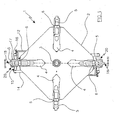
- Figure 1 is a plan view of the self-centering unit of the invention from above.
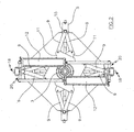
- Figure 2 is a plan view of the self-centering unit of the invention from below.
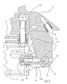
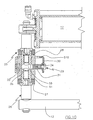
- Figure 3 shows the section III-III of Figure 1 .
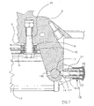
- Figure 4 is an enlarged-scale view of a detail of Figure 3 .
- Figure 5 is a three-dimensional view of part of a detail of the invention.
- Figures 6 and 7 show the view of Figure 4 in different operative stages.
- Figure 8 is a side view of a variant according to the invention.
- a self-centering unit 1 comprising a horizontal plate 2 to be associated with a vertical shaft 3 branching from the base of a usual tire removal machine, not shown.
- the purpose of the shaft 3 is to rotate the self-centering unit 1 during the demounting or mounting of the tire from or on the wheel rim by the usual means with which the tire removal machine is provided.
- the plate 1 presents four angularly equidistant identical radial slots 4.
- a slide 5 ( Figure 1 ) provided on its upper side with a double acting clamping jaw 6, i.e. able to lock a wheel rim 7, shown by dashed and dotted lines in Figure 3 , from the inside or from the outside.
- each slide 5 lowerly presents a threaded pin 55 ( Figure 4 ), the axis of which intersects the longitudinal axis of the corresponding radial slot 4, and on which there is mounted a bush 8 on which a pair of identical overlying connecting rods 9 are pivoted by way of an interposed spacer 10.
- the opposing ends of the connecting rods 9 are hinged to the corners of two identical overlying square plates 11 ( Figure 2 ) mounted idly on the shaft 3, so that the two connecting rods 9 of each pair are disposed symmetrical about the direction in which the corresponding clamping jaw 5 travels ( Figure 2 ).
- the function of the plates 11 and connecting rods 9 is to link together all the clamping jaws which grip the edge of the wheel rim 7 such that they are always equidistant from the axis of the shaft 3 of the tire removal machine.
- Two opposing slides 5 are associated, via a positioner device 20, with two cylinder-piston units 12 disposed on one and the other side of the shaft 3, their function being to move the clamping jaws towards or away from the axis of the shaft 3, to hence cause the clamping jaws to translate radially.
- Said two opposing slides 5 present lowerly ( Figure 5 ) a descending central stem 13 which terminates with a bush 14 provided with two opposing holes 140 and 141 perpendicular to the axis of the bush.
- the bush 14 is connected to the said positioner device 20, which comprises a crankshaft 15 provided with a crank 16, on the crankpin 17 of which the bush 14 is mounted.
- the ends of the crankshaft 15 are connected respectively to said pneumatic cylinder-piston units 12.
- Rotating the crankshaft 15 causes the working position of the clamping jaws to vary, i.e. causes them to approach or withdraw from the axis of the shaft 3 without modifying the travel stroke of the clamping jaws.
- This advantageously enables the self-centering unit to operate even on large-dimension wheel rims, i.e. with diameters exceeding 20 inches.
- the positioner device 20 also comprises means 18 for locking the crankshaft 17 in two opposing working positions, in which the clamping jaws are at their closest point to and farthest point from the shaft axis respectively.
- said means 18 are fixed between the arms of the crank 16, and comprise a cup-shaped body 19 the end of which is provided with a hole 190.
- a pin 21 one end of which is intended to be received in one of the holes 140 of the bush 14, whereas the opposite end emerges from the cup-shaped body via said hole 190 and is connected to an operating knob 22.
- the pin is maintained normally urged into one of the holes 140 by a spring 23 mounted about the pin and contained within the cup-shaped body. Said spring 23 is compressed between the end of the cup-shaped body and an annular shoulder 200 on the pin 21.
- the operation of the invention is extremely simple.
- the operator When the operator is to operate on large-dimension wheel rims, i.e. of diameter exceeding 20 inches, he sets the positioner device as shown in Figure 3 .
- the operator extracts the pin 21 from the hole 141 and then rotates the shaft 15 through 180 degrees in a clockwise direction to bring the pin 21 in front of the hole 140.
- the knob At this point, by releasing the knob the pin penetrates into the hole and locks the clamping jaw in position. It should be noted that this operation can be performed on only one or on both of the positioner devices, depending on the diameter of the wheel rim on which to operate.
- Figures from 8 to 10 show a variant of the invention which differs from the aforedescribed embodiment with regard to the constructional form of the positioner device.
- the figures show two opposing slides presenting at their rear a descending central stem 50 which terminates with a bush 51 ( Figure 9 ) connected to the cylinder-piston units 12 via a positioner device 25.
- the positioner device 25 comprises a crankshaft 26 provided with a crank 27, on the crankpin 28 of which the bush 51 is mounted.
- the ends of the crankshaft 26 are connected respectively to said pneumatic cylinder-piston units 12.
- Rotating the crankshaft 26 causes the working position of the clamping jaws to vary, i.e. causes them to approach or withdraw from the axis of the shaft 3 without modifying the travel stroke of the clamping jaws.
- This advantageously enables the self-centering unit to operate even on large-dimension wheel rims, i.e. with diameters exceeding 20 inches.
- the positioner device 25 also comprises means 29 for locking the crankshaft 26 in two opposing working positions, in which the clamping jaws are at their closest to and farthest from the shaft axis respectively.
- Said locking means are associated with the bush 51, they comprising a U-shaped latch 30, the base wall of which presents a rectangular aperture 300 to be received by and to translate on two flat portions 510 of the bush 51.
- a pin 31 and a spring 32 are positioned in the arms of the latch 30.
- the pin 31 is normally received in a matching hole 33 in the crankpin 28 of the crank 27 by passing through a hole 34 in the bush.
- the spring 32 the function of which is to maintain the pin 31 within the hole 33, is positioned between said arm of the latch 30 and a corresponding cavity 35 provided in the bush wall.
- the operation of the invention is very simple. To position the device the operator moves the latch 30 against the action of the spring 32 so as to compress the spring 32 and hence cause the pin 31 to leave the hole 33. The operator then rotates the crankshaft 26 through 180 degrees and then releases the latch to cause the pin 31 to enter the hole 33 by the action of the spring 32.
Landscapes
- Engineering & Computer Science (AREA)
- Mechanical Engineering (AREA)
- Testing Of Balance (AREA)
- Hand Tools For Fitting Together And Separating, Or Other Hand Tools (AREA)
- Jigs For Machine Tools (AREA)
Claims (13)
- Selbstzentrierende Einheit für Reifendemontagemaschinen, einschließlich einer Platte (2), ausgestattet mit einer Vielzahl an winklig in gleichem Abstand zueinander stehenden radialen Schlitzen (4), in denen jeweils eine gleitende Spannklaue (6) aufgenommen wird, welche in das Ende einer Radfelge (7) greift, wobei die Spannklauen (6) so miteinander verbunden sind, dass sie in immer gleicher Entfernung zur Achse der Platte (2) stehen und wenigstens einer Spannklaue (6) Betätigungselemente zugeordnet werden, die sie dazu bringen, sich in radialer Richtung translatorisch fortzubewegen, [dadurch gekennzeichnet, dass] wobei zwischen der Spannklaue (6) und den Betätigungselementen eine Zustelleinrichtung (20, 25) zwischengeschaltet ist, die so angeordnet ist, dass sie die Arbeitsposition der Spannklauen (6) in Bezug auf die Betätigungselemente verändert, ohne dabei ihren Laufweg abzuwandeln, dadurch gekennzeichnet, dass die Zustelleinrichtung (20, 25) unabhängig voneinander arbeitende Drehgelenkelemente enthält, die mit den Betätigungselementen und Schließelementen zum Fixieren der Drehgelenkelemente in verschiedenen Arbeitspositionen verbunden sind.
- Eine selbstzentrierende Einheit nach Patentanspruch 1, dadurch gekennzeichnet, dass die Betätigungselemente je zwei entgegen gesetzten Spannklauen (6) zugeordnet sind.
- Eine selbstzentrierende Einheit nach Patentanspruch 1, dadurch gekennzeichnet, dass eine Zustelleinrichtung (20) für jede den Betätigungselementen zugeordnete Spannklaue (6) bereit steht.
- Eine selbstzentrierende Einheit nach Patentanspruch 1, gekennzeichnet dadurch, dass die Drehgelenkelemente eine Kurbelwelle (15) beinhalten, die mit einer Kurbel (16) ausgestattet ist, deren Kurbelzapfen (17) in einer starr mit der Spannklaue (6) verbundenen Buchse (14) aufgenommen wird und ferner dadurch, dass die äußeren Drehgelenke mit den Betätigungselementen und den Schließelementen zum Fixieren der Kurbelwelle (15) in verschiedenen Arbeitspositionen verbunden sind.
- Eine selbstzentrierende Einheit nach Patentanspruch 4, dadurch gekennzeichnet, dass die Schließelemente der Kurbelwelle (15) zugeordnet sind.
- Eine selbstzentrierende Einheit nach Patentanspruch 4, dadurch gekennzeichnet, dass die Schließelemente der Buchse (14) zugeordnet sind.
- Eine selbstzentrierende Einheit nach Patentanspruch 4, dadurch gekennzeichnet, dass die Seitenwand der Buchse wenigstens zwei Löcher (140, 141) aufweist, die winklig voneinander abstehen.
- Eine selbstzentrierende Einheit nach Patentanspruch 4, dadurch gekennzeichnet, dass die Elemente zum Fixieren der Zustelleinrichtung (20) in einer Position einen Bolzen (21) beinhalten.
- Eine Einheit nach Patentanspruch 8, dadurch gekennzeichnet, dass der Bolzen (21) elastisch durch die Aktion einer Feder (23) in einem der Löcher auf der Buchse (14) verbleibt.
- Eine Einheit nach Patentanspruch 8, dadurch gekennzeichnet, dass der Bolzen elastisch durch die Aktion einer Feder (23) in einem der Löcher im Kurbelzapfen der Kurbelwelle (15) verbleibt.
- Eine selbstzentrierende Einheit nach den Patentansprüchen 5 und 7, dadurch gekennzeichnet, dass die der Kurbelwelle zugeordneten Schließelemente einen becherförmigen Körper beinhalten, dessen Ende mit einem Loch versehen ist, und in dem sich ein Stift gleitend bewegt, dessen eines Ende in einem der Löcher der Buchse aufgenommen wird, wobei das entgegen gesetzte Ende durch das Loch des becherförmigen Körpers hervortritt und mit einem Antriebsknopf (28) verbunden ist und wobei der Stift elastisch in einem der Löcher der Buchse durch eine Feder verbleibt, welche auf dem Stift montiert ist und zwischen dem Ende des becherförmigen Körpers und einem Ansatz auf dem Stift agiert.
- Eine selbstzentrierende Einheit nach Patentanspruch 6, dadurch gekennzeichnet, dass die der Buchse zugeordneten Schließelemente eine U-förmige Sperre beinhalten, deren Basiswand eine rechteckige Öffnung aufweist, die von der Buchse aufgenommen wird, sich auf zwei Abflachungen derselben translatorisch bewegt und deren Arme mit einem Stift und einer Feder ausgestattet sind, wobei der Stift normalerweise in einem passenden Loch im Kurbelzapfen der Kurbel durch die Aktion der Feder aufgenommen wird.
- Eine selbstzentrierende Einheit nach Patentanspruch 1, dadurch gekennzeichnet, dass die die translatorische Bewegung der Spannklauen (6) verursachenden Elemente wenigstens eine pneumatische Zylinderkolbeneinheit beinhalten.
Applications Claiming Priority (2)
| Application Number | Priority Date | Filing Date | Title |
|---|---|---|---|
| ITRE20030089 | 2003-09-29 | ||
| IT000089A ITRE20030089A1 (it) | 2003-09-29 | 2003-09-29 | Gruppo autocentrante perfezionato. |
Publications (2)
| Publication Number | Publication Date |
|---|---|
| EP1518718A1 EP1518718A1 (de) | 2005-03-30 |
| EP1518718B1 true EP1518718B1 (de) | 2008-11-12 |
Family
ID=34179346
Family Applications (1)
| Application Number | Title | Priority Date | Filing Date |
|---|---|---|---|
| EP04077607A Expired - Lifetime EP1518718B1 (de) | 2003-09-29 | 2004-09-20 | Selbstzentrierendes Futter |
Country Status (5)
| Country | Link |
|---|---|
| US (1) | US7201204B2 (de) |
| EP (1) | EP1518718B1 (de) |
| DE (1) | DE602004017681D1 (de) |
| ES (1) | ES2314337T3 (de) |
| IT (1) | ITRE20030089A1 (de) |
Families Citing this family (19)
| Publication number | Priority date | Publication date | Assignee | Title |
|---|---|---|---|---|
| ITMO20050009A1 (it) * | 2005-01-19 | 2006-07-20 | Gino Ferrari | Apparato di serraggio. |
| ITMO20060141A1 (it) * | 2006-05-05 | 2007-11-06 | Giuliano Spa | Madrino per il montaggio di cerchi di ruote per veicoli su macchine da autofficina, particolarmente macchine smontagomme o simili |
| ITRE20070091A1 (it) * | 2007-07-30 | 2009-01-31 | Corghi Spa | '' macchina smontagomme perfezionata " |
| US8161650B2 (en) * | 2007-10-02 | 2012-04-24 | Android Industries Llc | Workcell for tire and wheel assembly including a tire inflating sub-station that utilizes a flexible flip seal |
| US8769807B2 (en) | 2007-10-02 | 2014-07-08 | Android Industries Llc | Apparatus for processing a tire-wheel assembly including weight application and balancing sub-stations |
| DE102007057484B3 (de) * | 2007-11-29 | 2009-06-18 | Snap-On Equipment S.R.L A Unico Socio, Correggio | Reifenmontiermaschine |
| US8307874B1 (en) | 2008-01-25 | 2012-11-13 | Hunter Engineering Company | Tire changing method and machine with angularly positionable drive axis |
| US8702081B2 (en) * | 2012-02-29 | 2014-04-22 | Karl C. S. Melchior | Clamping device for clamping a plurality of workpieces at predetermined angles |
| ITMO20120212A1 (it) * | 2012-09-07 | 2014-03-08 | Giuliano Group Spa | Apparecchiatura per il bloccaggio di cerchi di ruote per veicoli in macchine da autofficina o simili |
| FR2999225B1 (fr) * | 2012-12-06 | 2018-07-13 | Safran Aircraft Engines | Dispositif d'amortissement de vibrations pour la fabrication d'un rotor |
| CN103921621B (zh) * | 2014-04-10 | 2016-05-25 | 中意泰达(营口)汽车保修设备有限公司 | 轮胎拆装机可调转盘装置 |
| US20160176250A1 (en) * | 2014-12-18 | 2016-06-23 | Zong Hai | Rubber inlay claw |
| CA2923047C (en) * | 2016-03-08 | 2023-06-27 | Darcy Goossen | Device for handling tires |
| IT201600129591A1 (it) * | 2016-12-21 | 2018-06-21 | Butler Eng And Marketing S P A | Gruppo di serraggio per un cerchione di o per una ruota gommata |
| CN107571059A (zh) * | 2017-08-31 | 2018-01-12 | 中信戴卡股份有限公司 | 一种用于车轮偏心装夹的夹具 |
| CN108725106B (zh) * | 2018-06-26 | 2024-10-22 | 上海巴兰仕汽车检测设备股份有限公司 | 一种可调节工作台卡位的拆胎机 |
| GB2579861A (en) * | 2018-12-18 | 2020-07-08 | Top One Machinery Co Ltd | Wheel rim chuck with soft jaws |
| CN111331530A (zh) * | 2018-12-18 | 2020-06-26 | 旭正机械股份有限公司 | 轮圈软爪夹头 |
| CN114229456B (zh) * | 2022-01-27 | 2023-11-03 | 中原工学院 | 一种用于机械制造的新型机械夹爪 |
Family Cites Families (7)
| Publication number | Priority date | Publication date | Assignee | Title |
|---|---|---|---|---|
| US3156480A (en) * | 1962-11-19 | 1964-11-10 | Pandjiris Weldment Company | Self-centering chuck mechanism |
| US3923090A (en) * | 1972-08-07 | 1975-12-02 | Gary W Kinney | Device for spoking and aligning wire wheels |
| US4034786A (en) * | 1975-11-17 | 1977-07-12 | Royal Industries, Inc. | Wheel chuck |
| EP0167195B1 (de) * | 1984-06-29 | 1990-12-12 | du Quesne, Francis | Mechanismus für das Befestigen einer Radfelge auf eine Reifenmontage- und -demontageeinrichtung |
| US4884611A (en) * | 1988-10-24 | 1989-12-05 | Schmidt Raymond H | Tire changing machine |
| US6039104A (en) * | 1998-03-06 | 2000-03-21 | Hennessy Industries, Inc. | Dual purpose clamp for rim holding tire changers |
| US6062289A (en) * | 1998-03-24 | 2000-05-16 | Hennessy Industries, Inc. | Laminated clamp for rim holding tire changers |
-
2003
- 2003-09-29 IT IT000089A patent/ITRE20030089A1/it unknown
- 2003-11-03 US US10/698,359 patent/US7201204B2/en not_active Expired - Lifetime
-
2004
- 2004-09-20 DE DE602004017681T patent/DE602004017681D1/de not_active Expired - Lifetime
- 2004-09-20 ES ES04077607T patent/ES2314337T3/es not_active Expired - Lifetime
- 2004-09-20 EP EP04077607A patent/EP1518718B1/de not_active Expired - Lifetime
Also Published As
| Publication number | Publication date |
|---|---|
| US20050067115A1 (en) | 2005-03-31 |
| US7201204B2 (en) | 2007-04-10 |
| EP1518718A1 (de) | 2005-03-30 |
| DE602004017681D1 (de) | 2008-12-24 |
| ITRE20030089A1 (it) | 2005-03-30 |
| ES2314337T3 (es) | 2009-03-16 |
Similar Documents
| Publication | Publication Date | Title |
|---|---|---|
| EP1518718B1 (de) | Selbstzentrierendes Futter | |
| EP2425993B1 (de) | Vorrichtung zum Spannen von Radfelgen für Fahrzeuge auf Werkstattmaschinen, insbesondere auf Reifenwechselmaschinen oder dergleichen | |
| US6516855B2 (en) | Wheel rim locking device for tire removal machines | |
| CN101754876B (zh) | 用于换胎机的卡盘 | |
| JP2002029231A (ja) | タイヤ取り外し機用の自動ビード解放装置及びそれを具備したタイヤ取り外し機 | |
| US9168797B2 (en) | Tyre demounting machine | |
| US6240995B1 (en) | Tire removal machine and relative accessories | |
| EP2551131B1 (de) | Vorrichtung zum Spannen von Radfelgen für Fahrzeuge auf Aufnahmen von Reifenwechselmaschinen | |
| IT9046883A1 (it) | Macchina smontagomme con autrocentrante reclinabile. | |
| EP2705964B1 (de) | Anwendung zum Fixieren von Radfelgen auf Reparaturwerkstattmaschinen oder dergleichen | |
| EP1844959B1 (de) | Verfahren und Gerät zum Entfernen eines mit einem starren inneren Notlaufring versehenen Reifens | |
| US4811774A (en) | Tire Changer safety arm | |
| US4293020A (en) | Tire changing apparatus | |
| EP1167087B1 (de) | Vorrichtung zur Operation auf "system pax"- Reifen oder ähnlichem | |
| CN211195734U (zh) | 一种便捷轮胎扒胎装置 | |
| JP2000335214A (ja) | 手動または自動配置可能なタレット付のタイヤ取り外し機械 | |
| CN114179572B (zh) | 用于锁定轮辋或车轮的锁紧头和快速锁紧装置 | |
| US11813901B2 (en) | Device for clamping a rim of a vehicle wheel | |
| EP1236589A2 (de) | Verbesserte Vorrichtung zum Montieren und Abmontieren von "system pax"- Leerlaufreifen und ähnliche | |
| EP0987130A2 (de) | Reifendemontiergerät | |
| JPH0747822A (ja) | ホイールリムからタイヤビードを外すための、タイヤ取外し機械用ビード解放ユニツト |
Legal Events
| Date | Code | Title | Description |
|---|---|---|---|
| PUAI | Public reference made under article 153(3) epc to a published international application that has entered the european phase |
Free format text: ORIGINAL CODE: 0009012 |
|
| AK | Designated contracting states |
Kind code of ref document: A1 Designated state(s): AT BE BG CH CY CZ DE DK EE ES FI FR GB GR HU IE IT LI LU MC NL PL PT RO SE SI SK TR |
|
| AX | Request for extension of the european patent |
Extension state: AL HR LT LV MK |
|
| 17P | Request for examination filed |
Effective date: 20050630 |
|
| AKX | Designation fees paid |
Designated state(s): DE ES FR GB IT |
|
| 17Q | First examination report despatched |
Effective date: 20061124 |
|
| GRAP | Despatch of communication of intention to grant a patent |
Free format text: ORIGINAL CODE: EPIDOSNIGR1 |
|
| GRAS | Grant fee paid |
Free format text: ORIGINAL CODE: EPIDOSNIGR3 |
|
| GRAA | (expected) grant |
Free format text: ORIGINAL CODE: 0009210 |
|
| AK | Designated contracting states |
Kind code of ref document: B1 Designated state(s): DE ES FR GB IT |
|
| REG | Reference to a national code |
Ref country code: GB Ref legal event code: FG4D |
|
| REF | Corresponds to: |
Ref document number: 602004017681 Country of ref document: DE Date of ref document: 20081224 Kind code of ref document: P |
|
| REG | Reference to a national code |
Ref country code: ES Ref legal event code: FG2A Ref document number: 2314337 Country of ref document: ES Kind code of ref document: T3 |
|
| PLBE | No opposition filed within time limit |
Free format text: ORIGINAL CODE: 0009261 |
|
| STAA | Information on the status of an ep patent application or granted ep patent |
Free format text: STATUS: NO OPPOSITION FILED WITHIN TIME LIMIT |
|
| 26N | No opposition filed |
Effective date: 20090813 |
|
| PGFP | Annual fee paid to national office [announced via postgrant information from national office to epo] |
Ref country code: GB Payment date: 20110930 Year of fee payment: 8 |
|
| GBPC | Gb: european patent ceased through non-payment of renewal fee |
Effective date: 20120920 |
|
| PG25 | Lapsed in a contracting state [announced via postgrant information from national office to epo] |
Ref country code: GB Free format text: LAPSE BECAUSE OF NON-PAYMENT OF DUE FEES Effective date: 20120920 |
|
| REG | Reference to a national code |
Ref country code: FR Ref legal event code: PLFP Year of fee payment: 12 |
|
| REG | Reference to a national code |
Ref country code: FR Ref legal event code: PLFP Year of fee payment: 13 |
|
| REG | Reference to a national code |
Ref country code: FR Ref legal event code: PLFP Year of fee payment: 14 |
|
| REG | Reference to a national code |
Ref country code: DE Ref legal event code: R082 Ref document number: 602004017681 Country of ref document: DE Representative=s name: LORENZ & KOLLEGEN PATENTANWAELTE PARTNERSCHAFT, DE Ref country code: DE Ref legal event code: R081 Ref document number: 602004017681 Country of ref document: DE Owner name: NEXION S.P.A., IT Free format text: FORMER OWNER: CORGHI S.P.A., CORREGGIO, REGGIO EMILIA, IT |
|
| REG | Reference to a national code |
Ref country code: ES Ref legal event code: PC2A Effective date: 20180529 Ref country code: ES Ref legal event code: PC2A Owner name: NEXION S.P.A. Effective date: 20180529 |
|
| REG | Reference to a national code |
Ref country code: FR Ref legal event code: CD Owner name: NEXION S.P.A., IT Effective date: 20180620 |
|
| REG | Reference to a national code |
Ref country code: FR Ref legal event code: PLFP Year of fee payment: 15 |
|
| P01 | Opt-out of the competence of the unified patent court (upc) registered |
Effective date: 20230530 |
|
| PGFP | Annual fee paid to national office [announced via postgrant information from national office to epo] |
Ref country code: FR Payment date: 20230926 Year of fee payment: 20 Ref country code: DE Payment date: 20230928 Year of fee payment: 20 |
|
| PGFP | Annual fee paid to national office [announced via postgrant information from national office to epo] |
Ref country code: ES Payment date: 20231017 Year of fee payment: 20 |
|
| PGFP | Annual fee paid to national office [announced via postgrant information from national office to epo] |
Ref country code: IT Payment date: 20230925 Year of fee payment: 20 |
|
| REG | Reference to a national code |
Ref country code: DE Ref legal event code: R071 Ref document number: 602004017681 Country of ref document: DE |
|
| REG | Reference to a national code |
Ref country code: ES Ref legal event code: FD2A Effective date: 20240927 |
|
| PG25 | Lapsed in a contracting state [announced via postgrant information from national office to epo] |
Ref country code: ES Free format text: LAPSE BECAUSE OF EXPIRATION OF PROTECTION Effective date: 20240921 |
|
| PG25 | Lapsed in a contracting state [announced via postgrant information from national office to epo] |
Ref country code: ES Free format text: LAPSE BECAUSE OF EXPIRATION OF PROTECTION Effective date: 20240921 |