EP1518718B1 - Improved self-centering unit - Google Patents
Improved self-centering unit Download PDFInfo
- Publication number
- EP1518718B1 EP1518718B1 EP04077607A EP04077607A EP1518718B1 EP 1518718 B1 EP1518718 B1 EP 1518718B1 EP 04077607 A EP04077607 A EP 04077607A EP 04077607 A EP04077607 A EP 04077607A EP 1518718 B1 EP1518718 B1 EP 1518718B1
- Authority
- EP
- European Patent Office
- Prior art keywords
- self
- pin
- centering unit
- bush
- crankshaft
- Prior art date
- Legal status (The legal status is an assumption and is not a legal conclusion. Google has not performed a legal analysis and makes no representation as to the accuracy of the status listed.)
- Active
Links
- 210000000078 claw Anatomy 0.000 description 7
- 239000000969 carrier Substances 0.000 description 1
- 230000009977 dual effect Effects 0.000 description 1
- 239000000284 extract Substances 0.000 description 1
- 125000006850 spacer group Chemical group 0.000 description 1
Images


Classifications
-
- B—PERFORMING OPERATIONS; TRANSPORTING
- B60—VEHICLES IN GENERAL
- B60C—VEHICLE TYRES; TYRE INFLATION; TYRE CHANGING; CONNECTING VALVES TO INFLATABLE ELASTIC BODIES IN GENERAL; DEVICES OR ARRANGEMENTS RELATED TO TYRES
- B60C25/00—Apparatus or tools adapted for mounting, removing or inspecting tyres
- B60C25/01—Apparatus or tools adapted for mounting, removing or inspecting tyres for removing tyres from or mounting tyres on wheels
- B60C25/05—Machines
- B60C25/053—Support of wheel parts during machine operation
- B60C25/0545—Support of wheel parts during machine operation with rotary motion of tool or tyre support, e.g. turntables
-
- B—PERFORMING OPERATIONS; TRANSPORTING
- B60—VEHICLES IN GENERAL
- B60C—VEHICLE TYRES; TYRE INFLATION; TYRE CHANGING; CONNECTING VALVES TO INFLATABLE ELASTIC BODIES IN GENERAL; DEVICES OR ARRANGEMENTS RELATED TO TYRES
- B60C25/00—Apparatus or tools adapted for mounting, removing or inspecting tyres
- B60C25/01—Apparatus or tools adapted for mounting, removing or inspecting tyres for removing tyres from or mounting tyres on wheels
- B60C25/05—Machines
- B60C25/053—Support of wheel parts during machine operation
- B60C25/0539—Support of wheel parts during machine operation radially fixing the rim, e.g. with gripping claws
-
- B—PERFORMING OPERATIONS; TRANSPORTING
- B60—VEHICLES IN GENERAL
- B60C—VEHICLE TYRES; TYRE INFLATION; TYRE CHANGING; CONNECTING VALVES TO INFLATABLE ELASTIC BODIES IN GENERAL; DEVICES OR ARRANGEMENTS RELATED TO TYRES
- B60C25/00—Apparatus or tools adapted for mounting, removing or inspecting tyres
- B60C25/01—Apparatus or tools adapted for mounting, removing or inspecting tyres for removing tyres from or mounting tyres on wheels
- B60C25/05—Machines
- B60C25/132—Machines for removing and mounting tyres
Definitions
- a self-centering unit comprising a horizontal plate mounted on an underlying vertical shaft of the tire removal machine. Said plate presents a circumferential series of angularly equidistant radial slots, with each of which there is associated a slide carrying a head or clamping jaw for gripping the edge of the wheel rim from the inside or outside.
- the clamp includes a base, a body and claws for gripping the rim of a tire.
- the base is generally L-shaped and includes perpendicular legs comprising spaced apart walls which define interior channels. Rails are mounted along a portion of the inner surface of the walls of each leg, and are configured to slidably engage oppositely disposed channels formed on the clamp carriers of the tire changer.
- Each leg of the base further includes a bore formed therein and configured to receive a locking pin for releasably securing the clamp to the clamp carrier in the desired position.
- First and second claws are attached to the body opposite the base.
- the second claw is preferably disposed ninety degrees from the first claw so that the clamp may be reoriented.
- the first claw is configured to accommodate a first rim type
- the second claw is configured to accommodate a second rim type.
- the claws are releasably secured to a clamp carrier on the base and must be detached in order to be reoriented.
- the object of the present invention is to overcome the drawbacks of the known art within the context of a simple and rational solution.
- the invention provides a self-centering unit comprising a plate provided with a series of angularly equidistant radial slots, in each of which a clamping jaw is received and slides to grip the edge of a wheel rim, said clamping jaws being linked together in such a manner as to be always equidistant from the axis of said plate, at least one clamping jaw being associated with actuator means for translating it in a radial direction.
- a positioner device arranged to vary the working position of said clamping jaws relative to the actuator means, without modifying their travel stroke.
- said actuator means are associated with two opposing clamping jaws, a positioner device being interposed between each clamping jaw and the actuator means.
- said actuator means for translating the clamping jaws are at least one pneumatic cylinder-piston unit.
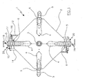
- Figure 1 is a plan view of the self-centering unit of the invention from above.
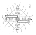
- Figure 2 is a plan view of the self-centering unit of the invention from below.
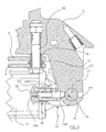
- Figure 3 shows the section III-III of Figure 1 .
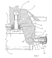
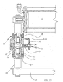
- Figure 4 is an enlarged-scale view of a detail of Figure 3 .
- Figure 5 is a three-dimensional view of part of a detail of the invention.
- Figures 6 and 7 show the view of Figure 4 in different operative stages.
- Figure 8 is a side view of a variant according to the invention.
- a self-centering unit 1 comprising a horizontal plate 2 to be associated with a vertical shaft 3 branching from the base of a usual tire removal machine, not shown.
- the purpose of the shaft 3 is to rotate the self-centering unit 1 during the demounting or mounting of the tire from or on the wheel rim by the usual means with which the tire removal machine is provided.
- the plate 1 presents four angularly equidistant identical radial slots 4.
- a slide 5 ( Figure 1 ) provided on its upper side with a double acting clamping jaw 6, i.e. able to lock a wheel rim 7, shown by dashed and dotted lines in Figure 3 , from the inside or from the outside.
- each slide 5 lowerly presents a threaded pin 55 ( Figure 4 ), the axis of which intersects the longitudinal axis of the corresponding radial slot 4, and on which there is mounted a bush 8 on which a pair of identical overlying connecting rods 9 are pivoted by way of an interposed spacer 10.
- the opposing ends of the connecting rods 9 are hinged to the corners of two identical overlying square plates 11 ( Figure 2 ) mounted idly on the shaft 3, so that the two connecting rods 9 of each pair are disposed symmetrical about the direction in which the corresponding clamping jaw 5 travels ( Figure 2 ).
- the function of the plates 11 and connecting rods 9 is to link together all the clamping jaws which grip the edge of the wheel rim 7 such that they are always equidistant from the axis of the shaft 3 of the tire removal machine.
- Two opposing slides 5 are associated, via a positioner device 20, with two cylinder-piston units 12 disposed on one and the other side of the shaft 3, their function being to move the clamping jaws towards or away from the axis of the shaft 3, to hence cause the clamping jaws to translate radially.
- Said two opposing slides 5 present lowerly ( Figure 5 ) a descending central stem 13 which terminates with a bush 14 provided with two opposing holes 140 and 141 perpendicular to the axis of the bush.
- the bush 14 is connected to the said positioner device 20, which comprises a crankshaft 15 provided with a crank 16, on the crankpin 17 of which the bush 14 is mounted.
- the ends of the crankshaft 15 are connected respectively to said pneumatic cylinder-piston units 12.
- Rotating the crankshaft 15 causes the working position of the clamping jaws to vary, i.e. causes them to approach or withdraw from the axis of the shaft 3 without modifying the travel stroke of the clamping jaws.
- This advantageously enables the self-centering unit to operate even on large-dimension wheel rims, i.e. with diameters exceeding 20 inches.
- the positioner device 20 also comprises means 18 for locking the crankshaft 17 in two opposing working positions, in which the clamping jaws are at their closest point to and farthest point from the shaft axis respectively.
- said means 18 are fixed between the arms of the crank 16, and comprise a cup-shaped body 19 the end of which is provided with a hole 190.
- a pin 21 one end of which is intended to be received in one of the holes 140 of the bush 14, whereas the opposite end emerges from the cup-shaped body via said hole 190 and is connected to an operating knob 22.
- the pin is maintained normally urged into one of the holes 140 by a spring 23 mounted about the pin and contained within the cup-shaped body. Said spring 23 is compressed between the end of the cup-shaped body and an annular shoulder 200 on the pin 21.
- the operation of the invention is extremely simple.
- the operator When the operator is to operate on large-dimension wheel rims, i.e. of diameter exceeding 20 inches, he sets the positioner device as shown in Figure 3 .
- the operator extracts the pin 21 from the hole 141 and then rotates the shaft 15 through 180 degrees in a clockwise direction to bring the pin 21 in front of the hole 140.
- the knob At this point, by releasing the knob the pin penetrates into the hole and locks the clamping jaw in position. It should be noted that this operation can be performed on only one or on both of the positioner devices, depending on the diameter of the wheel rim on which to operate.
- Figures from 8 to 10 show a variant of the invention which differs from the aforedescribed embodiment with regard to the constructional form of the positioner device.
- the figures show two opposing slides presenting at their rear a descending central stem 50 which terminates with a bush 51 ( Figure 9 ) connected to the cylinder-piston units 12 via a positioner device 25.
- the positioner device 25 comprises a crankshaft 26 provided with a crank 27, on the crankpin 28 of which the bush 51 is mounted.
- the ends of the crankshaft 26 are connected respectively to said pneumatic cylinder-piston units 12.
- Rotating the crankshaft 26 causes the working position of the clamping jaws to vary, i.e. causes them to approach or withdraw from the axis of the shaft 3 without modifying the travel stroke of the clamping jaws.
- This advantageously enables the self-centering unit to operate even on large-dimension wheel rims, i.e. with diameters exceeding 20 inches.
- the positioner device 25 also comprises means 29 for locking the crankshaft 26 in two opposing working positions, in which the clamping jaws are at their closest to and farthest from the shaft axis respectively.
- Said locking means are associated with the bush 51, they comprising a U-shaped latch 30, the base wall of which presents a rectangular aperture 300 to be received by and to translate on two flat portions 510 of the bush 51.
- a pin 31 and a spring 32 are positioned in the arms of the latch 30.
- the pin 31 is normally received in a matching hole 33 in the crankpin 28 of the crank 27 by passing through a hole 34 in the bush.
- the spring 32 the function of which is to maintain the pin 31 within the hole 33, is positioned between said arm of the latch 30 and a corresponding cavity 35 provided in the bush wall.
- the operation of the invention is very simple. To position the device the operator moves the latch 30 against the action of the spring 32 so as to compress the spring 32 and hence cause the pin 31 to leave the hole 33. The operator then rotates the crankshaft 26 through 180 degrees and then releases the latch to cause the pin 31 to enter the hole 33 by the action of the spring 32.
Description
- The present patent relates to a self-centering unit to be associated with tire removal machines, to maintain wheel rims locked in a horizontal position while demounting and/or mounting the corresponding tires.
- The automobile industry currently markets vehicles provided with wheel rims of a diameter which exceeds the range within which traditional self-centering units operate.
- To be able to also operate on large-dimension wheel rims, a self-centering unit is known comprising a horizontal plate mounted on an underlying vertical shaft of the tire removal machine. Said plate presents a circumferential series of angularly equidistant radial slots, with each of which there is associated a slide carrying a head or clamping jaw for gripping the edge of the wheel rim from the inside or outside.
- The head is associated with the slide in such a manner as to be able to translate in the direction of the travel axis of the slide in order to occupy two different operative positions, locking means being present to lock the head in the chosen operative position.
- Although the described device performs the function for which it is provided, it presents certain drawbacks. A first drawback is the need to individually move each head relative to the slide to adapt the self-centering unit to large-dimension wheel rims. This operation is lengthy and laborious, the operator often forgetting to move a head, with the result that when the wheel rim is gripped by the heads it is not in the correct working position and risks undergoing damage.
- D1:
US 6,039,104 discloses a dual purpose clamp for use in connection with rim holding tire changers with features according to the preamble of claims 1. The clamp includes a base, a body and claws for gripping the rim of a tire. In the preferred embodiment, the base is generally L-shaped and includes perpendicular legs comprising spaced apart walls which define interior channels. Rails are mounted along a portion of the inner surface of the walls of each leg, and are configured to slidably engage oppositely disposed channels formed on the clamp carriers of the tire changer. Each leg of the base further includes a bore formed therein and configured to receive a locking pin for releasably securing the clamp to the clamp carrier in the desired position. First and second claws are attached to the body opposite the base. The second claw is preferably disposed ninety degrees from the first claw so that the clamp may be reoriented. The first claw is configured to accommodate a first rim type, and the second claw is configured to accommodate a second rim type. The claws are releasably secured to a clamp carrier on the base and must be detached in order to be reoriented. - The object of the present invention is to overcome the drawbacks of the known art within the context of a simple and rational solution.
- The invention achieves said object by virtue of the characteristics defined in the claims.
- Specifically, the invention provides a self-centering unit comprising a plate provided with a series of angularly equidistant radial slots, in each of which a clamping jaw is received and slides to grip the edge of a wheel rim, said clamping jaws being linked together in such a manner as to be always equidistant from the axis of said plate, at least one clamping jaw being associated with actuator means for translating it in a radial direction.
- According to the invention, between said at least one clamping jaw and said actuator means there is provided a positioner device arranged to vary the working position of said clamping jaws relative to the actuator means, without modifying their travel stroke.
- In a preferred embodiment of the invention, said actuator means are associated with two opposing clamping jaws, a positioner device being interposed between each clamping jaw and the actuator means.
- According to the invention, said actuator means for translating the clamping jaws are at least one pneumatic cylinder-piston unit.
- The characteristics and constructional merits of the invention will be apparent from the ensuing detailed description given with reference to the figures of the accompanying drawings, which illustrate a particular preferred embodiment thereof by way of non-limiting example.
-
Figure 1 is a plan view of the self-centering unit of the invention from above. -
Figure 2 is a plan view of the self-centering unit of the invention from below. -
Figure 3 shows the section III-III ofFigure 1 . -
Figure 4 is an enlarged-scale view of a detail ofFigure 3 . -
Figure 5 is a three-dimensional view of part of a detail of the invention. -
Figures 6 and7 show the view ofFigure 4 in different operative stages. -
Figure 8 is a side view of a variant according to the invention. - Said figures show a self-centering unit 1 comprising a
horizontal plate 2 to be associated with avertical shaft 3 branching from the base of a usual tire removal machine, not shown. - The purpose of the
shaft 3 is to rotate the self-centering unit 1 during the demounting or mounting of the tire from or on the wheel rim by the usual means with which the tire removal machine is provided. - The plate 1 presents four angularly equidistant identical
radial slots 4. In eachslot 4 there is slidingly mounted a slide 5 (Figure 1 ) provided on its upper side with a double actingclamping jaw 6, i.e. able to lock awheel rim 7, shown by dashed and dotted lines inFigure 3 , from the inside or from the outside. - With reference to
Figures 2 ,3 and4 , eachslide 5 lowerly presents a threaded pin 55 (Figure 4 ), the axis of which intersects the longitudinal axis of the correspondingradial slot 4, and on which there is mounted abush 8 on which a pair of identical overlying connectingrods 9 are pivoted by way of an interposedspacer 10. The opposing ends of the connectingrods 9 are hinged to the corners of two identical overlying square plates 11 (Figure 2 ) mounted idly on theshaft 3, so that the two connectingrods 9 of each pair are disposed symmetrical about the direction in which thecorresponding clamping jaw 5 travels (Figure 2 ). The function of theplates 11 and connectingrods 9 is to link together all the clamping jaws which grip the edge of thewheel rim 7 such that they are always equidistant from the axis of theshaft 3 of the tire removal machine. - Two
opposing slides 5 are associated, via apositioner device 20, with two cylinder-piston units 12 disposed on one and the other side of theshaft 3, their function being to move the clamping jaws towards or away from the axis of theshaft 3, to hence cause the clamping jaws to translate radially. - Said two
opposing slides 5 present lowerly (Figure 5 ) a descendingcentral stem 13 which terminates with abush 14 provided with twoopposing holes bush 14 is connected to the saidpositioner device 20, which comprises acrankshaft 15 provided with acrank 16, on thecrankpin 17 of which thebush 14 is mounted. The ends of thecrankshaft 15 are connected respectively to said pneumatic cylinder-piston units 12. - Rotating the
crankshaft 15 causes the working position of the clamping jaws to vary, i.e. causes them to approach or withdraw from the axis of theshaft 3 without modifying the travel stroke of the clamping jaws. This advantageously enables the self-centering unit to operate even on large-dimension wheel rims, i.e. with diameters exceeding 20 inches. - The
positioner device 20 also comprises means 18 for locking thecrankshaft 17 in two opposing working positions, in which the clamping jaws are at their closest point to and farthest point from the shaft axis respectively. - With reference to
Figure 4 , saidmeans 18 are fixed between the arms of thecrank 16, and comprise a cup-shaped body 19 the end of which is provided with ahole 190. Within the cup-shaped body 19 there slides apin 21, one end of which is intended to be received in one of theholes 140 of thebush 14, whereas the opposite end emerges from the cup-shaped body via saidhole 190 and is connected to anoperating knob 22. The pin is maintained normally urged into one of theholes 140 by aspring 23 mounted about the pin and contained within the cup-shaped body. Saidspring 23 is compressed between the end of the cup-shaped body and anannular shoulder 200 on thepin 21. - The operation of the invention is extremely simple. When the operator is to operate on large-dimension wheel rims, i.e. of diameter exceeding 20 inches, he sets the positioner device as shown in
Figure 3 . To achieve this, starting from the position ofFigure 7 the operator extracts thepin 21 from thehole 141 and then rotates theshaft 15 through 180 degrees in a clockwise direction to bring thepin 21 in front of thehole 140. At this point, by releasing the knob the pin penetrates into the hole and locks the clamping jaw in position. It should be noted that this operation can be performed on only one or on both of the positioner devices, depending on the diameter of the wheel rim on which to operate. - Figures from 8 to 10 show a variant of the invention which differs from the aforedescribed embodiment with regard to the constructional form of the positioner device.
- In the description of this variant of the invention, those components identical to and already described in the first embodiment of the invention are indicated by the same reference numerals.
- The figures show two opposing slides presenting at their rear a descending
central stem 50 which terminates with a bush 51 (Figure 9 ) connected to the cylinder-piston units 12 via apositioner device 25. - The
positioner device 25 comprises acrankshaft 26 provided with acrank 27, on thecrankpin 28 of which thebush 51 is mounted. The ends of thecrankshaft 26 are connected respectively to said pneumatic cylinder-piston units 12. - Rotating the
crankshaft 26 causes the working position of the clamping jaws to vary, i.e. causes them to approach or withdraw from the axis of theshaft 3 without modifying the travel stroke of the clamping jaws. This advantageously enables the self-centering unit to operate even on large-dimension wheel rims, i.e. with diameters exceeding 20 inches. - The
positioner device 25 also comprises means 29 for locking thecrankshaft 26 in two opposing working positions, in which the clamping jaws are at their closest to and farthest from the shaft axis respectively. Said locking means are associated with thebush 51, they comprising aU-shaped latch 30, the base wall of which presents arectangular aperture 300 to be received by and to translate on twoflat portions 510 of thebush 51. Apin 31 and aspring 32 are positioned in the arms of thelatch 30. - The
pin 31 is normally received in amatching hole 33 in thecrankpin 28 of thecrank 27 by passing through ahole 34 in the bush. Thespring 32, the function of which is to maintain thepin 31 within thehole 33, is positioned between said arm of thelatch 30 and acorresponding cavity 35 provided in the bush wall. - Again in this case the operation of the invention is very simple. To position the device the operator moves the
latch 30 against the action of thespring 32 so as to compress thespring 32 and hence cause thepin 31 to leave thehole 33. The operator then rotates thecrankshaft 26 through 180 degrees and then releases the latch to cause thepin 31 to enter thehole 33 by the action of thespring 32.
Claims (13)
- A self-centering unit for tire removal machines, comprising a plate (2) provided with a series of angularly equidistant radial slots (4), in each of which a clamping jaw (6) is received and slides to grip the edge of a wheel rim (7), said clamping jaws (6) being linked together in such a manner as to be always equidistant from the axis of said plate (2), at least one clamping jaw (6) being associated with actuator means causing it to translate in a radial direction, [characterized in that] wherein between said at least one clamping jaw (6) and said actuator means there is interposed a positioner device (20, 25) arranged to vary the working position of said clamping jaws (6) relative to the actuator means, without modifying their travel stroke, characterized in that said positioner device (20, 25) comprises independently operating pivoting means connected to said actuator means and means for locking said pivoting means in different working positions.
- A self-centering unit as claimed in claim 1, characterized in that said actuator means are associated with two opposing clamping jaws (6).
- A self-centering unit as claimed in claim 1, characterized by providing a positioner device (20) for each clamping jaw (6) associated with said actuator means.
- A self-centering unit as claimed in claim 1, characterized by the fact that said pivoting means comprise a crankshaft (15) provided with a crank (16), of which the crankpin (17) is received in a bush (14) rigid with said clamping jaw (6) and the outer pivots are connected to said actuator means, and means for locking said crankshaft (15) in different working positions.
- A self-centering unit as claimed in claim 4, characterized in that said locking means are associated with said crankshaft (15).
- A self-centering unit as claimed in claim 4, characterized in that said locking means are associated with the bush (14).
- A self-centering unit as claimed in claim 4, characterized in that the lateral wall of said bush presents at least two holes (140, 141) angularly spaced apart.
- A self-centering unit as claimed in claim 4, characterized in that said means for locking said positioner device (20) in position comprise a pin (21).
- A unit as claimed in claim 8, characterized in that said pin (21) is elastically maintained inserted in one of the holes present in said bush (14) by the action of a spring (23).
- A unit as claimed in claim 8, characterized in that said pin is elastically maintained in a hole present in the crankpin of the crankshaft (15) by the action of a spring (23).
- A self-centering unit as claimed in claims 5 and 7, characterized in that said locking means associated with said crankshaft comprise a cup-shaped body the end of which is provided with a hole, and within which there slides a pin, one end of which is intended to be received in one of the holes of the bush, whereas the opposite end emerges from the cup-shaped body via said hole and is connected to an operating knob (28), said pin being elastically maintained within one of the holes of the bush by a spring which is mounted about the pin and acts between the end of said cup-shaped body and a shoulder on the pin.
- A self-centering unit as claimed in claim 6, characterized in that said locking means associated with the bush comprise a U-shaped latch, the base wall of which presents a rectangular aperture to be received by and to translate on two flat portions of the bush, and the arms of which are provided with a pin and a spring, said pin being normally received in a matching hole in the crankpin of the crank by the action of said spring.
- A self-centering unit as claimed in claim 1, characterized in that said means for causing the clamping jaws (6) to translate comprise at least one pneumatic cylinder-piston unit.
Applications Claiming Priority (2)
| Application Number | Priority Date | Filing Date | Title |
|---|---|---|---|
| IT000089A ITRE20030089A1 (en) | 2003-09-29 | 2003-09-29 | PERFORMED SELF-CENTERING GROUP. |
| ITRE20030089 | 2003-09-29 |
Publications (2)
| Publication Number | Publication Date |
|---|---|
| EP1518718A1 EP1518718A1 (en) | 2005-03-30 |
| EP1518718B1 true EP1518718B1 (en) | 2008-11-12 |
Family
ID=34179346
Family Applications (1)
| Application Number | Title | Priority Date | Filing Date |
|---|---|---|---|
| EP04077607A Active EP1518718B1 (en) | 2003-09-29 | 2004-09-20 | Improved self-centering unit |
Country Status (5)
| Country | Link |
|---|---|
| US (1) | US7201204B2 (en) |
| EP (1) | EP1518718B1 (en) |
| DE (1) | DE602004017681D1 (en) |
| ES (1) | ES2314337T3 (en) |
| IT (1) | ITRE20030089A1 (en) |
Families Citing this family (19)
| Publication number | Priority date | Publication date | Assignee | Title |
|---|---|---|---|---|
| ITMO20050009A1 (en) * | 2005-01-19 | 2006-07-20 | Gino Ferrari | TIGHTENING APPARATUS. |
| ITMO20060141A1 (en) * | 2006-05-05 | 2007-11-06 | Giuliano Spa | MOTHER FOR ASSEMBLY OF WHEEL RIMS FOR VEHICLES ON CARS, ESPECIALLY SIMILAR MACHINES |
| ITRE20070091A1 (en) * | 2007-07-30 | 2009-01-31 | Corghi Spa | '' PERFORMED TANK MACHINE " |
| US8161650B2 (en) * | 2007-10-02 | 2012-04-24 | Android Industries Llc | Workcell for tire and wheel assembly including a tire inflating sub-station that utilizes a flexible flip seal |
| US8769807B2 (en) | 2007-10-02 | 2014-07-08 | Android Industries Llc | Apparatus for processing a tire-wheel assembly including weight application and balancing sub-stations |
| DE102007057484B3 (en) * | 2007-11-29 | 2009-06-18 | Snap-On Equipment S.R.L A Unico Socio, Correggio | tire changer |
| US8307874B1 (en) | 2008-01-25 | 2012-11-13 | Hunter Engineering Company | Tire changing method and machine with angularly positionable drive axis |
| US8702081B2 (en) * | 2012-02-29 | 2014-04-22 | Karl C. S. Melchior | Clamping device for clamping a plurality of workpieces at predetermined angles |
| ITMO20120212A1 (en) * | 2012-09-07 | 2014-03-08 | Giuliano Group Spa | EQUIPMENT FOR LOCKING WHEEL RIMS FOR VEHICLES IN AUTOMATIC OR SIMILAR MACHINES |
| FR2999225B1 (en) * | 2012-12-06 | 2018-07-13 | Safran Aircraft Engines | DEVICE FOR DAMPING VIBRATIONS FOR THE MANUFACTURE OF A ROTOR |
| CN103921621B (en) * | 2014-04-10 | 2016-05-25 | 中意泰达(营口)汽车保修设备有限公司 | Tire changer is adjustable rotating-table apparatus |
| US20160176250A1 (en) * | 2014-12-18 | 2016-06-23 | Zong Hai | Rubber inlay claw |
| CA2923047C (en) * | 2016-03-08 | 2023-06-27 | Darcy Goossen | Device for handling tires |
| IT201600129591A1 (en) * | 2016-12-21 | 2018-06-21 | Butler Eng And Marketing S P A | TIGHTENING ASSEMBLY FOR A RIM OF OR FOR A WHEELED WHEEL |
| CN107571059A (en) * | 2017-08-31 | 2018-01-12 | 中信戴卡股份有限公司 | A kind of fixture for wheel eccentricities clamping |
| CN108725106A (en) * | 2018-06-26 | 2018-11-02 | 上海巴兰仕汽车检测设备股份有限公司 | A kind of tyre detacher of adjustable working table screens |
| GB2579861A (en) * | 2018-12-18 | 2020-07-08 | Top One Machinery Co Ltd | Wheel rim chuck with soft jaws |
| CN111331530A (en) * | 2018-12-18 | 2020-06-26 | 旭正机械股份有限公司 | Soft claw chuck for wheel rim |
| CN114229456B (en) * | 2022-01-27 | 2023-11-03 | 中原工学院 | Novel mechanical clamping jaw for mechanical manufacturing |
Family Cites Families (7)
| Publication number | Priority date | Publication date | Assignee | Title |
|---|---|---|---|---|
| US3156480A (en) * | 1962-11-19 | 1964-11-10 | Pandjiris Weldment Company | Self-centering chuck mechanism |
| US3923090A (en) * | 1972-08-07 | 1975-12-02 | Gary W Kinney | Device for spoking and aligning wire wheels |
| US4034786A (en) * | 1975-11-17 | 1977-07-12 | Royal Industries, Inc. | Wheel chuck |
| EP0167195B1 (en) * | 1984-06-29 | 1990-12-12 | du Quesne, Francis | Mechanism for fixing a wheel to an apparatus for mounting or removing a tyre on or from a rim |
| US4884611A (en) * | 1988-10-24 | 1989-12-05 | Schmidt Raymond H | Tire changing machine |
| US6039104A (en) | 1998-03-06 | 2000-03-21 | Hennessy Industries, Inc. | Dual purpose clamp for rim holding tire changers |
| US6062289A (en) * | 1998-03-24 | 2000-05-16 | Hennessy Industries, Inc. | Laminated clamp for rim holding tire changers |
-
2003
- 2003-09-29 IT IT000089A patent/ITRE20030089A1/en unknown
- 2003-11-03 US US10/698,359 patent/US7201204B2/en not_active Expired - Lifetime
-
2004
- 2004-09-20 DE DE602004017681T patent/DE602004017681D1/en active Active
- 2004-09-20 EP EP04077607A patent/EP1518718B1/en active Active
- 2004-09-20 ES ES04077607T patent/ES2314337T3/en active Active
Also Published As
| Publication number | Publication date |
|---|---|
| DE602004017681D1 (en) | 2008-12-24 |
| ES2314337T3 (en) | 2009-03-16 |
| ITRE20030089A1 (en) | 2005-03-30 |
| US7201204B2 (en) | 2007-04-10 |
| EP1518718A1 (en) | 2005-03-30 |
| US20050067115A1 (en) | 2005-03-31 |
Similar Documents
| Publication | Publication Date | Title |
|---|---|---|
| EP1518718B1 (en) | Improved self-centering unit | |
| EP2425993B1 (en) | Device for clamping wheel rims for vehicles on repair workshop machines, particularly tyre-changing machines or the like | |
| US6516855B2 (en) | Wheel rim locking device for tire removal machines | |
| EP0947360B1 (en) | Tyre removal machine and relative accessories | |
| JP2002029231A (en) | Automatic bead releasing device for tire removing machine and tire removing machine provided with it | |
| US8376018B2 (en) | Chuck for a tyre changing machine | |
| US9168797B2 (en) | Tyre demounting machine | |
| EP2551131B1 (en) | Device for locking rims of a vehicle on supporting means of a tyre servicing machine | |
| EP2705964B1 (en) | Appliance for locking wheel rims for vehicles on repair workshop machines or the like | |
| EP1844959B1 (en) | Method and machine for removing a tyre fitted with a rigid inner run-flat ring | |
| US4811774A (en) | Tire Changer safety arm | |
| EP1167087B1 (en) | Device for operating on tyres of "system pax" type and the like | |
| US4293020A (en) | Tire changing apparatus | |
| CN114179572B (en) | Locking head and quick locking device for locking a rim or wheel | |
| US11813901B2 (en) | Device for clamping a rim of a vehicle wheel | |
| EP1236589A2 (en) | Improved implement for demounting and mounting self-supporting tyres of the system pax type and the like | |
| EP0987130A2 (en) | Device for tyre removal machines | |
| JP3752066B2 (en) | Grooving device for side ring of vehicle wheel rim | |
| JPH09267285A (en) | Automatic tool change mechanism of handling device |
Legal Events
| Date | Code | Title | Description |
|---|---|---|---|
| PUAI | Public reference made under article 153(3) epc to a published international application that has entered the european phase |
Free format text: ORIGINAL CODE: 0009012 |
|
| AK | Designated contracting states |
Kind code of ref document: A1 Designated state(s): AT BE BG CH CY CZ DE DK EE ES FI FR GB GR HU IE IT LI LU MC NL PL PT RO SE SI SK TR |
|
| AX | Request for extension of the european patent |
Extension state: AL HR LT LV MK |
|
| 17P | Request for examination filed |
Effective date: 20050630 |
|
| AKX | Designation fees paid |
Designated state(s): DE ES FR GB IT |
|
| 17Q | First examination report despatched |
Effective date: 20061124 |
|
| GRAP | Despatch of communication of intention to grant a patent |
Free format text: ORIGINAL CODE: EPIDOSNIGR1 |
|
| GRAS | Grant fee paid |
Free format text: ORIGINAL CODE: EPIDOSNIGR3 |
|
| GRAA | (expected) grant |
Free format text: ORIGINAL CODE: 0009210 |
|
| AK | Designated contracting states |
Kind code of ref document: B1 Designated state(s): DE ES FR GB IT |
|
| REG | Reference to a national code |
Ref country code: GB Ref legal event code: FG4D |
|
| REF | Corresponds to: |
Ref document number: 602004017681 Country of ref document: DE Date of ref document: 20081224 Kind code of ref document: P |
|
| REG | Reference to a national code |
Ref country code: ES Ref legal event code: FG2A Ref document number: 2314337 Country of ref document: ES Kind code of ref document: T3 |
|
| PLBE | No opposition filed within time limit |
Free format text: ORIGINAL CODE: 0009261 |
|
| STAA | Information on the status of an ep patent application or granted ep patent |
Free format text: STATUS: NO OPPOSITION FILED WITHIN TIME LIMIT |
|
| 26N | No opposition filed |
Effective date: 20090813 |
|
| PGFP | Annual fee paid to national office [announced via postgrant information from national office to epo] |
Ref country code: GB Payment date: 20110930 Year of fee payment: 8 |
|
| GBPC | Gb: european patent ceased through non-payment of renewal fee |
Effective date: 20120920 |
|
| PG25 | Lapsed in a contracting state [announced via postgrant information from national office to epo] |
Ref country code: GB Free format text: LAPSE BECAUSE OF NON-PAYMENT OF DUE FEES Effective date: 20120920 |
|
| REG | Reference to a national code |
Ref country code: FR Ref legal event code: PLFP Year of fee payment: 12 |
|
| REG | Reference to a national code |
Ref country code: FR Ref legal event code: PLFP Year of fee payment: 13 |
|
| REG | Reference to a national code |
Ref country code: FR Ref legal event code: PLFP Year of fee payment: 14 |
|
| REG | Reference to a national code |
Ref country code: DE Ref legal event code: R082 Ref document number: 602004017681 Country of ref document: DE Representative=s name: LORENZ & KOLLEGEN PATENTANWAELTE PARTNERSCHAFT, DE Ref country code: DE Ref legal event code: R081 Ref document number: 602004017681 Country of ref document: DE Owner name: NEXION S.P.A., IT Free format text: FORMER OWNER: CORGHI S.P.A., CORREGGIO, REGGIO EMILIA, IT |
|
| REG | Reference to a national code |
Ref country code: ES Ref legal event code: PC2A Effective date: 20180529 Ref country code: ES Ref legal event code: PC2A Owner name: NEXION S.P.A. Effective date: 20180529 |
|
| REG | Reference to a national code |
Ref country code: FR Ref legal event code: CD Owner name: NEXION S.P.A., IT Effective date: 20180620 |
|
| REG | Reference to a national code |
Ref country code: FR Ref legal event code: PLFP Year of fee payment: 15 |
|
| P01 | Opt-out of the competence of the unified patent court (upc) registered |
Effective date: 20230530 |
|
| PGFP | Annual fee paid to national office [announced via postgrant information from national office to epo] |
Ref country code: FR Payment date: 20230926 Year of fee payment: 20 Ref country code: DE Payment date: 20230928 Year of fee payment: 20 |
|
| PGFP | Annual fee paid to national office [announced via postgrant information from national office to epo] |
Ref country code: ES Payment date: 20231017 Year of fee payment: 20 |
|
| PGFP | Annual fee paid to national office [announced via postgrant information from national office to epo] |
Ref country code: IT Payment date: 20230925 Year of fee payment: 20 |