EP1518613B1 - Einrichtung zur wärmebehandlung von pulverabfällen - Google Patents
Einrichtung zur wärmebehandlung von pulverabfällen Download PDFInfo
- Publication number
- EP1518613B1 EP1518613B1 EP03761757A EP03761757A EP1518613B1 EP 1518613 B1 EP1518613 B1 EP 1518613B1 EP 03761757 A EP03761757 A EP 03761757A EP 03761757 A EP03761757 A EP 03761757A EP 1518613 B1 EP1518613 B1 EP 1518613B1
- Authority
- EP
- European Patent Office
- Prior art keywords
- container
- gas
- vertical
- powdery waste
- cylindrical heat
- Prior art date
- Legal status (The legal status is an assumption and is not a legal conclusion. Google has not performed a legal analysis and makes no representation as to the accuracy of the status listed.)
- Expired - Lifetime
Links
Images



Classifications
-
- F—MECHANICAL ENGINEERING; LIGHTING; HEATING; WEAPONS; BLASTING
- F23—COMBUSTION APPARATUS; COMBUSTION PROCESSES
- F23G—CREMATION FURNACES; CONSUMING WASTE PRODUCTS BY COMBUSTION
- F23G5/00—Incineration of waste; Incinerator constructions; Details, accessories or control therefor
- F23G5/44—Details; Accessories
- F23G5/46—Recuperation of heat
-
- B—PERFORMING OPERATIONS; TRANSPORTING
- B01—PHYSICAL OR CHEMICAL PROCESSES OR APPARATUS IN GENERAL
- B01J—CHEMICAL OR PHYSICAL PROCESSES, e.g. CATALYSIS OR COLLOID CHEMISTRY; THEIR RELEVANT APPARATUS
- B01J8/00—Chemical or physical processes in general, conducted in the presence of fluids and solid particles; Apparatus for such processes
- B01J8/18—Chemical or physical processes in general, conducted in the presence of fluids and solid particles; Apparatus for such processes with fluidised particles
- B01J8/1836—Heating and cooling the reactor
-
- B—PERFORMING OPERATIONS; TRANSPORTING
- B01—PHYSICAL OR CHEMICAL PROCESSES OR APPARATUS IN GENERAL
- B01J—CHEMICAL OR PHYSICAL PROCESSES, e.g. CATALYSIS OR COLLOID CHEMISTRY; THEIR RELEVANT APPARATUS
- B01J8/00—Chemical or physical processes in general, conducted in the presence of fluids and solid particles; Apparatus for such processes
- B01J8/18—Chemical or physical processes in general, conducted in the presence of fluids and solid particles; Apparatus for such processes with fluidised particles
- B01J8/1881—Chemical or physical processes in general, conducted in the presence of fluids and solid particles; Apparatus for such processes with fluidised particles with particles moving downwards while fluidised
-
- B—PERFORMING OPERATIONS; TRANSPORTING
- B01—PHYSICAL OR CHEMICAL PROCESSES OR APPARATUS IN GENERAL
- B01J—CHEMICAL OR PHYSICAL PROCESSES, e.g. CATALYSIS OR COLLOID CHEMISTRY; THEIR RELEVANT APPARATUS
- B01J8/00—Chemical or physical processes in general, conducted in the presence of fluids and solid particles; Apparatus for such processes
- B01J8/18—Chemical or physical processes in general, conducted in the presence of fluids and solid particles; Apparatus for such processes with fluidised particles
- B01J8/24—Chemical or physical processes in general, conducted in the presence of fluids and solid particles; Apparatus for such processes with fluidised particles according to "fluidised-bed" technique
- B01J8/38—Chemical or physical processes in general, conducted in the presence of fluids and solid particles; Apparatus for such processes with fluidised particles according to "fluidised-bed" technique with fluidised bed containing a rotatable device or being subject to rotation or to a circulatory movement, i.e. leaving a vessel and subsequently re-entering it
- B01J8/382—Chemical or physical processes in general, conducted in the presence of fluids and solid particles; Apparatus for such processes with fluidised particles according to "fluidised-bed" technique with fluidised bed containing a rotatable device or being subject to rotation or to a circulatory movement, i.e. leaving a vessel and subsequently re-entering it with a rotatable device only
-
- B—PERFORMING OPERATIONS; TRANSPORTING
- B09—DISPOSAL OF SOLID WASTE; RECLAMATION OF CONTAMINATED SOIL
- B09B—DISPOSAL OF SOLID WASTE NOT OTHERWISE PROVIDED FOR
- B09B3/00—Destroying solid waste or transforming solid waste into something useful or harmless
- B09B3/30—Destroying solid waste or transforming solid waste into something useful or harmless involving mechanical treatment
- B09B3/38—Stirring or kneading
-
- B—PERFORMING OPERATIONS; TRANSPORTING
- B09—DISPOSAL OF SOLID WASTE; RECLAMATION OF CONTAMINATED SOIL
- B09B—DISPOSAL OF SOLID WASTE NOT OTHERWISE PROVIDED FOR
- B09B3/00—Destroying solid waste or transforming solid waste into something useful or harmless
- B09B3/40—Destroying solid waste or transforming solid waste into something useful or harmless involving thermal treatment, e.g. evaporation
-
- C—CHEMISTRY; METALLURGY
- C10—PETROLEUM, GAS OR COKE INDUSTRIES; TECHNICAL GASES CONTAINING CARBON MONOXIDE; FUELS; LUBRICANTS; PEAT
- C10J—PRODUCTION OF PRODUCER GAS, WATER-GAS, SYNTHESIS GAS FROM SOLID CARBONACEOUS MATERIAL, OR MIXTURES CONTAINING THESE GASES; CARBURETTING AIR OR OTHER GASES
- C10J3/00—Production of combustible gases containing carbon monoxide from solid carbonaceous fuels
- C10J3/02—Fixed-bed gasification of lump fuel
- C10J3/20—Apparatus; Plants
- C10J3/32—Devices for distributing fuel evenly over the bed or for stirring up the fuel bed
-
- C—CHEMISTRY; METALLURGY
- C10—PETROLEUM, GAS OR COKE INDUSTRIES; TECHNICAL GASES CONTAINING CARBON MONOXIDE; FUELS; LUBRICANTS; PEAT
- C10J—PRODUCTION OF PRODUCER GAS, WATER-GAS, SYNTHESIS GAS FROM SOLID CARBONACEOUS MATERIAL, OR MIXTURES CONTAINING THESE GASES; CARBURETTING AIR OR OTHER GASES
- C10J3/00—Production of combustible gases containing carbon monoxide from solid carbonaceous fuels
- C10J3/46—Gasification of granular or pulverulent flues in suspension
- C10J3/48—Apparatus; Plants
- C10J3/482—Gasifiers with stationary fluidised bed
-
- F—MECHANICAL ENGINEERING; LIGHTING; HEATING; WEAPONS; BLASTING
- F23—COMBUSTION APPARATUS; COMBUSTION PROCESSES
- F23G—CREMATION FURNACES; CONSUMING WASTE PRODUCTS BY COMBUSTION
- F23G5/00—Incineration of waste; Incinerator constructions; Details, accessories or control therefor
- F23G5/24—Incineration of waste; Incinerator constructions; Details, accessories or control therefor having a vertical, substantially cylindrical, combustion chamber
- F23G5/28—Incineration of waste; Incinerator constructions; Details, accessories or control therefor having a vertical, substantially cylindrical, combustion chamber having raking arms
-
- F—MECHANICAL ENGINEERING; LIGHTING; HEATING; WEAPONS; BLASTING
- F23—COMBUSTION APPARATUS; COMBUSTION PROCESSES
- F23G—CREMATION FURNACES; CONSUMING WASTE PRODUCTS BY COMBUSTION
- F23G5/00—Incineration of waste; Incinerator constructions; Details, accessories or control therefor
- F23G5/30—Incineration of waste; Incinerator constructions; Details, accessories or control therefor having a fluidised bed
-
- B—PERFORMING OPERATIONS; TRANSPORTING
- B01—PHYSICAL OR CHEMICAL PROCESSES OR APPARATUS IN GENERAL
- B01J—CHEMICAL OR PHYSICAL PROCESSES, e.g. CATALYSIS OR COLLOID CHEMISTRY; THEIR RELEVANT APPARATUS
- B01J2208/00—Processes carried out in the presence of solid particles; Reactors therefor
- B01J2208/00008—Controlling the process
- B01J2208/00017—Controlling the temperature
- B01J2208/00106—Controlling the temperature by indirect heat exchange
- B01J2208/00168—Controlling the temperature by indirect heat exchange with heat exchange elements outside the bed of solid particles
-
- B—PERFORMING OPERATIONS; TRANSPORTING
- B01—PHYSICAL OR CHEMICAL PROCESSES OR APPARATUS IN GENERAL
- B01J—CHEMICAL OR PHYSICAL PROCESSES, e.g. CATALYSIS OR COLLOID CHEMISTRY; THEIR RELEVANT APPARATUS
- B01J2208/00—Processes carried out in the presence of solid particles; Reactors therefor
- B01J2208/00796—Details of the reactor or of the particulate material
- B01J2208/00823—Mixing elements
- B01J2208/00858—Moving elements
- B01J2208/00867—Moving elements inside the bed, e.g. rotary mixer
-
- B—PERFORMING OPERATIONS; TRANSPORTING
- B09—DISPOSAL OF SOLID WASTE; RECLAMATION OF CONTAMINATED SOIL
- B09B—DISPOSAL OF SOLID WASTE NOT OTHERWISE PROVIDED FOR
- B09B2101/00—Type of solid waste
- B09B2101/30—Incineration ashes
-
- C—CHEMISTRY; METALLURGY
- C10—PETROLEUM, GAS OR COKE INDUSTRIES; TECHNICAL GASES CONTAINING CARBON MONOXIDE; FUELS; LUBRICANTS; PEAT
- C10J—PRODUCTION OF PRODUCER GAS, WATER-GAS, SYNTHESIS GAS FROM SOLID CARBONACEOUS MATERIAL, OR MIXTURES CONTAINING THESE GASES; CARBURETTING AIR OR OTHER GASES
- C10J2300/00—Details of gasification processes
- C10J2300/12—Heating the gasifier
- C10J2300/1269—Heating the gasifier by radiating device, e.g. radiant tubes
- C10J2300/1276—Heating the gasifier by radiating device, e.g. radiant tubes by electricity, e.g. resistor heating
-
- F—MECHANICAL ENGINEERING; LIGHTING; HEATING; WEAPONS; BLASTING
- F23—COMBUSTION APPARATUS; COMBUSTION PROCESSES
- F23G—CREMATION FURNACES; CONSUMING WASTE PRODUCTS BY COMBUSTION
- F23G2209/00—Specific waste
- F23G2209/30—Solid combustion residues, e.g. bottom or flyash
-
- Y—GENERAL TAGGING OF NEW TECHNOLOGICAL DEVELOPMENTS; GENERAL TAGGING OF CROSS-SECTIONAL TECHNOLOGIES SPANNING OVER SEVERAL SECTIONS OF THE IPC; TECHNICAL SUBJECTS COVERED BY FORMER USPC CROSS-REFERENCE ART COLLECTIONS [XRACs] AND DIGESTS
- Y02—TECHNOLOGIES OR APPLICATIONS FOR MITIGATION OR ADAPTATION AGAINST CLIMATE CHANGE
- Y02P—CLIMATE CHANGE MITIGATION TECHNOLOGIES IN THE PRODUCTION OR PROCESSING OF GOODS
- Y02P20/00—Technologies relating to chemical industry
- Y02P20/10—Process efficiency
- Y02P20/129—Energy recovery, e.g. by cogeneration, H2recovery or pressure recovery turbines
Definitions
- the present invention relates to an apparatus for treating powdery waste by heating.
- the present invention relates to an apparatus for treating waste ash incinerated from refuses and the like by heating, in order to evaporate and remove dioxin, from the ash incinerated from refuse.
- the dioxin exists in incineration flue gas that is discharged from the wasted refuse incinerator, in fly ash that is collected from the flue gas, and in bottom ash that is discharged from an incineration furnace.
- Examined Japanese patent publication No. H-06-038863 discloses a method for decomposing dioxin by various catalysts.
- the publication also discloses a method for catalytically decomposing activated carbon and the like, which are used to collect dioxin by heating to gasify the dioxin, and a method for catalytically decomposing fly ash by heating under the atmospheric condition of deficient oxygen.
- the patent publication does not disclose the concrete structure of the apparatus in detail, which is for heating to gasify the object.
- Japanese Patent No. 2512665 JP-A-H-06-159646 , (the term "JP-A” referred herein signifies "Japanese Patent Laid-Open No.”) discloses a method for treating ash incinerated from refuse by heating, which is discharged from waste incineration facilities to decompose the existing organic chloride compounds in the ash incinerated from refuse, wherein the ash incinerated from refuse is heated within a range from 350 °C to 550°C, by submitting lime to the ash incinerated from refuse.
- the method secondary discloses that the ash incinerated from refuse is quenched to the equal or less than 250°C.
- the apparatus used in the ash incinerated from refuse treatment is a type of a horizontal rotary kiln.
- JP-A-2000-16844 discloses a method for heating and decomposing dioxin by heating a material containing dioxin to the boiling temperature or more of dioxin. And the method discloses how to introduce the gas containing the vaporized dioxin into a cement-calcinination rotary kiln and how to decompose the dioxin by using the heat generated during calcining the cement.
- the heating apparatus such as the conventional rotary kiln has one of problem that efficient heat transfer cannot be obtained from the heated surface area to the wasted material area. Consequently, in case that the inefficient heat transfer goes on, it is required to rise the heated wall surface excessively, to a degree of the sufficient temperature for removing the dioxin. Such excessive heating causes an increase in the heating energy, which is required for heating. Additionally, the wasted refuse is apt to be adhesive to the inside surface of the heating apparatus, resulting from reaching to the excessive temperature. Therefore, the operational trouble is apt to happen from time to time.
- a paddle blade may be used to remove the adhered material. This may be effective for scraping the material adhered to the wall surface. However, it is required to give a lot of power, in order to scrap the adhered material. As a result, the paddles have a possibility to receive the damage and to be abrasive. And as a result, high torque is required to drive the paddle.
- Such an apparatus is known from document EP 1 197 270 A1 .
- the apparatus enables us to remove the dioxin efficiently, where the dioxin exists in the bottom ash and in the fly ash generated from wasted refuse incineration furnace.
- the apparatus makes it possible to detoxify the waste efficiently.
- the apparatus has an excellent characteristic that the peripheral walls of the vertical and cylindrical heat-container are used as the heated surface.
- the apparatus has agitator blades, which is structured of multistage paddle blades and, which is located inside the container. According to the heating apparatus of the present invention, air is injected from the bottom of the vertical and cylindrical container, where the waste is filled up, into the upper side of the container. At the same time, the agitator blades are used for agitating the material.
- the exchange rate of the particles against the wall of the fluidized bed layer becomes high.
- Such high exchange rate makes it possible to heat efficiently, whether heating by hot air is applied to or heating through the apparatus wall from the outside of the fluidized bed is applied to.
- a drying device where the hot air is usable as the fluid, becomes in practical use.
- the fluidized condition in the fluidized bed is significantly influenced by the fluidized particles (kinds of the wasted material), the flow rate of the fluid, and the shapes of the agitator blades structured by the paddle blades, and by other factors.
- the characteristic of the heat transfer is significantly dictated by the above-mentioned factors.
- the agitator blades made of paddle blades are essential for fluidizing the fine particles, some types of the shape of the agitator blades may make it impossible to enhance fluidizing particles. And they may result in degrading the advantage of the vertical and cylindrical heating apparatus provided with the agitator blades.
- the inventors of the present invention studied to solve the above-described problems, focusing on how to minimize the force for pushing the powdery waste in the rotational direction of the rotary agitator blades.
- the inventors have conceived and found out that how effective the agitator blade area horizontally projected is minimized.
- the inventors of the present invention have found the following good results. That is, combination of the fluidized bed heating apparatus with the paddle blades having small horizontally projected area enables us to fluidize powdery waste favorably, secures efficient treatment of powdery waste. And this enables us to solve the problem of the solid material adhesive to the inner peripheral wall of the heating apparatus.
- the present invention has been studied and developed, based on the above-described findings, and provides the following apparatus and the method.
- the vertical and cylindrical heat-container contains a powdery material holding section for holding the powdery material.
- the container may be a straight cylinder or the container may be a cylinder that has different diameters at sections.
- the cylinder has a shorter diameter and a longer diameter, whichever is shorter and whichever is longer, concerning a tapered cylinder configuration between a top portion and a bottom portion. Both of the top face and the bottom face of the container are normally closed.
- the container forms, totally, an enclosed structure. Both of the top face and the bottom face of the container possess, respectively, a flat face, a curved face, a conical face, or the like.
- the capacity of the container is designed, taking the quantity of the treated powdery material into consideration. Normally, however, the capacity of the container is within a range approximately from 0.01 to 100 m 3 , particularly approximately from 0.2 to 10 m 3 .
- the heat-container needs an inlet and an outlet for the powdery wasted material, in order for the gas to fluidize the powdery wasted material.
- the gas inlet opening and the gas outlet opening are provided at the bottom portion and the top portion of the heat-container, respectively, in order to inject the gas beneath the powdery waste bed and to pass through the bed upward, thus fluidizing the powdery waste.
- the gas outlet opening has, as a case may be, a dust-removal device such as a dust filter, a cyclone, an electrostatic precipitator, or a ceramics filter.
- the inlet and outlet openings for the powdery waste may be placed at an arbitrary position, respectively, if they can charge a powdery waste or discharge a powdery waste.
- the charge opening for the powdery waste is preferably located at the upper portion of the container, and the discharge opening is preferably located at the lower portion of the container.
- one opening may be useable for both functions of the charge opening and the discharge opening.
- the gas which fluidizes the powdery wasted material, also has a transporting function to transport the vaporized dioxin by heating the gas.
- This transporting function is usable for discharging the vaporized dioxin from the inside of the container.
- the inlet opening for injecting the gas is located at the bottom portion of the container. For instance, the inlet opening is located at the bottom face or at the lower end of the side face of the container.
- the inlet opening for injecting the gas may be installed, taking the size of the heat-container into consideration, for instance, based on the capacity of the vertical cylinder.
- the inlet opening for injecting the gas may be single, or dual or more multiple of ring spurgers.
- the inlet opening for injecting the gas may have a perforated plate in order to uniform the blown gas and in order to prevent the powdery wasted material from entering into the inlet for injecting the gas.
- the injected amount of the gas is in a range of approximately from 0.01 to 2 Nm 3 /kg, preferably approximately from 0.1 to 1 Nm 3 /kg.
- the rate is approximately from 0.1 to 30 cm 3 /sec., and preferably approximately from 1 to 10 cm 3 /sec.
- the method for heating the wasted material in the heat-container which has a shape of the vertical cylinder, may be usable as various methods, for instance, a method for heating the gas from the external periphery of the cylinder, or a method for heating the gas by hot air, which fluidizes the powdery wasted material. It is preferable to apply both of the above-mentioned heating methods, simultaneously.
- the heat-container is provided with agitator blades for agitating the powdery wasted material.
- a typical agitator blade is a paddle blade.
- the blade is in a shape of a rod, a plate, and the like.
- the following figures of the cross section are applied to the rod. For instance, they are complete round, ellipse, two arcs joined together, square, rectangular, and hexagonal.
- Plate includes flat plate and trough. Plate may be located horizontally, tilting, or vertically, preferably horizontal to tilted positions giving angles of from 0 to 60 degrees to the horizontal plane, more preferably from 0 to 45 degrees.
- Each agitator blade extends in the outer direction, which is in the radial direction, from the rotary shaft.
- the direction may be horizontal (for example, Fig. 4 ).
- the direction may be tilt angle (for example, Fig. 9 ), or may be combination thereof (for example, Fig. 10 ).
- the vertical direction is, however, not preferable because the vertical direction gives less fluidization effect and pushes, slides and adheres the powdery wasted material to the inner wall surface of the heat-container.
- Preferable angles are ⁇ 60° to the horizontal plane, and more preferable angles are ⁇ 45°.
- the number of the agitator blades it is in a range from 2 to 20 sheets of the agitator blades per meter along the fluidized bed height.
- the mounted position of the right blade may be as the same as that of the left blade. Otherwise, it may be different position alternately. In case that the right blade has as the same position as the left blade, using the two blades, two sheets of the agitator blades become a single stage.
- Agitator blades may be arranged in linear allocation form the top view above, that is to say, allocated at every 180°. The allocation may be in three directions or in four directions (cross arrangement), or the like. Alternatively, the allocation may be arranged in spiral-staircase pattern. The position of the uppermost agitator blade may be above or beneath the top surface of the fluidized bed of the powdery waste.
- the agitator blades have 30% or less of the ratio of the horizontally projected area of the agitator blades to the area inside the envelope of the outermost edges of the agitator blades.
- the ratio is preferably 20% or less, and most preferably 15% or less.
- the lower limit of the projected area may be as small as possible, if the necessary strength of the agitator blade is kept. Normally, however, a preferred projected area is around 5%, and more preferably around 3%.
- the above-described envelope is normally in rectangular, trapezoid, or combination thereof.
- the horizontal projected area of the agitator blades is defined as the projection area formed when the members of both the agitator shaft and the blade section in the heating apparatus are projected on a vertical plane (in a horizontal direction).
- the area inside the envelope of the outermost edges of the agitator blades is very close to the vertical cross sectional area of the heat-container between the upper edge of the uppermost blade and the lower edge of the lowermost blade. Actually, since the length of the agitator blade is slightly less than the inner diameter of the heating apparatus, the projected area becomes slightly smaller than the corresponding cross sectional area of the heating apparatus.
- the agitator blades may be single. Otherwise, the agitator blades may be arranged in three or more directions, which is radial to the rotary shaft. In this case, the agitator blades pass the same position continuously inside the space of the heat-container, while the agitator blades rotate. So, whichever different radial directions the agitator blades are mounted mutually, the projected area does not increase. That is, the projected area means that the area formed by a singe agitator blade. In other words, however the different agitator blades, a typical agitator blade or each agitator blade repeats the rotation, the projected area is defined as the same projected pattern in the unit operation during repeating.
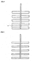
- Fig. 4 through 12 show examples of the agitator blades.
- the agitator blades shown in Fig. 4 comprise five pairs of plate blades, which are arranged in the horizontal direction, and which are arranged on both sides of the rotary shaft at an equal distance.
- the agitator blades repeats projection pattern of A.
- the rate of the projected area of the agitator blade according to the present invention is the rate of the projected area of the agitator blade in the area enveloped by A.
- the agitator blades of Fig. 5 through Fig. 7 have the blade shortened in the width thereof from that in Fig. 4 .
- the agitator blades in Fig. 7 are rods.
- the agitator blades in Fig. 8 are an example of lattice-arrangement of the rod blades.
- the agitator blades in Fig. 9 show an example of rod blades arranged in parallel to each other at 45° tilting angle.
- the agitator blades in Fig. 10 show an example that combines the rods, which are arranged in parallel to each other in the horizontal direction, with the rods, which are arranged in parallel to each other at 45° to the horizontal rods.
- the agitator blades show an example that arranges alternately the rods, which are on the right side and the left side in the horizontal direction.
- the agitator blades show an example that combines the rods arranged in parallel to each other in the horizontal direction, with the rods arranged in parallel to each other at 45° tilted to the horizontal rods.
- the agitator blades of Fig. 10 have the tilted blades in a straight shape. But, the agitator blades of Fig. 12 have the tilted blades folded at the rotary shaft, simultaneously facing the outer direction and facing the upward direction.
- the rotational speed of the agitator blades is in a range approximately from 1 to 200 rpm, preferably approximately from 10 to 100 rpm, and more preferably approximately from 30 to 60 rpm.
- the present invention has a various kind of powdery wasted material other than the exemplary embodiments.
- the adequate mean size of the powdery wasted particle is in a range of approximately from 0.1 to 1000 ⁇ m, normally approximately from 1 to 200 ⁇ m, preferably approximately from 1 to 50 ⁇ m.
- the density of the powdery wasted particle is approximately from 0.1 to 5 g/cm 3 , and normally approximately from 0.5 to 3 g/cm 3 .
- the following materials are described.
- ash wasted and incinerated from refuse or fly ash discharged from waste incineration furnace wasted material such as activated carbon contaminated by adsorbed organic halogen compounds such as dioxin, and sludge and mud generated from water treatment or from sewage treatment process.
- the powdery wasted material comprise sand, soil, river bottom mud, lake bottom mud, sea bottom mud, and slurry of wasted soil generated during digging and constructing a tunnel and the like, which are contaminated by organic matter, organic halide, heavy metal, and the like.
- applicable powdery wasted material contains organic halogen compounds at around 0.1 to 100 ng-TEQ/g, particularly around 1 to 10 ng-TEQ/g determined by the method of JIS K0311.
- the kind of gas used to fluidize the powdery waste may be adequately selected, taking the object of treatment into consideration.
- the gas is, normally, air, incinerator flue gas, nitrogen gas, steam, He, Ar, or the like.
- the heat-treatment apparatus is provided with adequate auxiliary facilities, depending on the object of the treatment.
- an apparatus for thermally decomposing the organic halogen compounds carried by the flue gas, or an apparatus for catalytically decomposing the organic halogen compounds may be additionally installed.
- the dust eliminator may be a bag filter, a cyclone, an electrostatic precipitator, a ceramics filter, and the like. Since the temperature of flue gas is in a range of from around 350°C to around 550°C and since the flue gas is further heated to be thermally decompose, the ceramics filter and the like which are applicable at high temperatures are preferred.
- a thermal decomposition apparatus is connected with.
- the gas which contains harmful organic halogen compounds, is heated to decompose the organic halogen compound.
- the gas is fed and treated in a catalytic reactor.
- the catalytic reactor catalytically decomposes the harmful organic halogen compound.
- the thermal decomposition apparatus has an inlet of gas being thermally decomposed in the closed space and this apparatus has an outlet of thermally decomposed gas.
- This thermal decomposition apparatus may make utilize of the general purpose type devices, which is used in high temperature combustion deodorization devices and the like.
- the present invention can apply the burner, the electric heater, the high frequency wave heater, the infrared heater, and a hot zone of waste incineration furnace, to the thermal decomposition apparatus.
- the catalytic reactor may be fixed bed type, moving bed type, or fluidized bed type.
- the catalyst is selected, depending on the kind of harmful organic halogen compound.
- an applicable catalyst includes: noble metal catalyst of at least one element selected from the group consisting of platinum group elements such as platinum, palladium, rhodium, and ruthenium, and gold; and oxide catalyst of at least one oxide of single or composite oxide of calcium, manganese, cobalt, chromium, iron, nickel, titanium, vanadium, and tungsten.
- the operating condition of the heat-treatment apparatus according to the present invention is influenced by the object of the treatment.
- the heating condition for treating a powdery wasted material contaminated by organic halogen compounds may be within a temperature range of around 350°C to around 550°C, preferably around 400°C to around 450°C.
- the average retention time is for around 5 to around 180 minutes, normally from around 30 to around 120 minutes.
- the organic halogen compounds are subjected to vaporization, and may be decomposed.
- the powdery wasted material after removed organic halogen compounds and the like in the heating apparatus is required to be subjected to the secondary treatment, or to be dumped, or to be further utilized.
- the gas containing vaporized organic halogen compounds is required to be subjected to dust-removal, and then is required to be subjected to decomposing the organic halogen compounds in the thermal decomposition apparatus or in the catalytic reactor.
- the thermal decomposition is carried out within temperatures from 800°C to 1000°C, preferably within temperatures approximately from 850°C to 950°C, in approximate average retention time from 0.5 to 20 seconds, preferably approximately from 1 to 5 seconds.
- the thermal decomposition decomposes the organic halogen compounds to the degree of about 50 to 95%, preferable to the degree of about 80 to 95%.
- the catalytic reaction is carried out within temperature from 150°C to 500°C, preferably approximately from 150°C to 400°C at space velocities of approximately from 1000 to 10000 hr -1 .
- the catalytic reaction decomposes the organic halogen compounds to the degree of about 90% or more, preferably 95% or more.
- the combined and simultaneous use of the thermal decomposition apparatus and the catalytic reactor brings up the increase in decomposing the organic halogen compounds at a high rate.
- space velocity (SV) signifies the amount of the gas volume.
- the condition for SV is regulated by flowing the gas inside the container, simultaneously with placing the solid inside the container.
- the value of the Space Velocity is defined as the amount of the treated gas volume, which is based on per unit solid volume and based on per unit time.
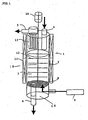
- Figure 1 illustrates the outline of the heat-treatment apparatus used in Example 1, according to the present invention.
- the heat treatment apparatus 1 is provided with a gas outlet opening 3 and a powdery waste inlet opening 4 at the upper portion of a cylindrical and vertical container 2, and with a gas introduction opening 5 and a powdery waste inlet opening 6 at the lower portion.
- the central portion of the container 2 is a powdery waste holding section 7.
- the powdery waste holding section 7 has a distributor 8, in order to distribute the gas at the bottom.
- a heater 11 is located at the outer periphery of the container 1 to heat the inner space of the container 1, while agitator blades 12 are located inside the container 1 to agitate the powdery waste.
- a dust collector 13 is located at the gas outlet opening 3 to remove the dust from the gas.
- a motor 14 is installed in order to rotate the agitator blades 12.
- a fluidization bed model was fabricated by attaching a compressed air cylinder 9 and a pressure gauge 10 to the heat-treatment apparatus, as shown in Fig. 2 .
- the pressure gauge 10 determines the pressure difference between a wind box under the gas distributor 8 and the space above the fluidizing bed of the powdery waste in the powdery waste holding section 7.
- the container 2 was made of acrylic resin, which had the inner diameter 120 mm, and the effective height 300 mm.
- the applied powdery waste was fly ash, which had the mean particle size 15 ⁇ m, sampled from a waste incineration furnace.
- the fly ash was filled in the layer, as a stationary height, 100 mm. Air at room temperature was injected into the container at a linear velocity 13 cm/sec inside the container, in order to fluidize the powdery waste, while rotating the agitator blades 12. The height was measured, resulting from such a fluidized bed.
- Table 1 shows the determined height of the fluidized bed at each mode.
- Table 1 Agitator blades Agitator blades Rate of projected area of agitator blades (%) Height of fluidized bed (Expansion rate) (mm) State of fluidization Tilted rod Symmetry/ Asymmetry
- Fig. 4 Not used Symmetry 50 105 (1.05) Fly ash rotates in the agitator rotary direction, rotary direction, and does not fluidize.
- Fig. 5 Not used Symmetry 30 125 (1.25) Fluidized while the rotation of fly ash in the agitator rotary direction is somewhat suppresses.
- Fig. 4 Not used Symmetry 50 105 (1.05)
- Fig. 11 Not used Asymmetry 5 or less 252 (1.52) Uniformly fluidized with very little move of fly ash in the agitator rotary direction.
- Fig. 12 Used Symmetry 5 or less 143 (1.43) Uniformly fluidized with very little move of fly ash in the agitator rotary direction.
- a waste treatment apparatus shown in Fig. 3 was fabricated by allocating, in line, the thermal decomposition apparatus and the catalytic reactor for decomposing the organic halogen compounds at the exit of the above-described heat-treatment apparatus.
- the electric heater was controlled by heating the gas to the extent of 900°C, and the length of the conduit was adjusted to gain for keeping the retention time of the gas within 2 seconds or more and for keeping the temperature 900°C.
- the catalysts were applied to the catalytic reactor, that is, a catalyst of platinum supported on a silica-alumina-base ceramics, whose catalyst support was in honeycomb shape.
- the quantity of catalyst was selected to ensure the space velocity 2000 hr -1 .
- the catalyst temperature was 400°C.
- the treated amount of the fly ash was 100 kg/h, whose fly ash was treated in the heating apparatus, being submitted at 420°C and for 60 minutes. Air was used as the gas to accelerate vaporization. The fly ash, which was discharged from the heating apparatus after the heat treatment, was detected but the detected amount was so low. The value was sufficiently low concentration level of the harmful organic matter, or 0.004 ng-TEQ/g.
- Dioxin differs in the toxicity, depending each isomer.
- the toxicity coefficient is defined to each dioxin, which coefficient is called the "toxicity equivalent factor".
- TEQ is the sum of the multiplicated results between the product of the concentration of each isomer and the toxicity equivalent factor.
- the flue gas discharged from the heating apparatus via a dust filter was treated by the respective three methods: (I) sole thermal decomposition apparatus, (II) sole catalytic reactor, and (III) combination of the thermal decomposition apparatus and the catalytic reactor.
- (I) sole thermal decomposition apparatus (II) sole catalytic reactor, and (III) combination of the thermal decomposition apparatus and the catalytic reactor.
- the fly ashes having different sludge concentration mutually, the research and the investigation was done, in case that the different dioxin concentrations exist in the flue gas.
- the present invention provides an apparatus for treating a powdery wasted material and a method the same.
- the invention enables the technological world to fluidize the powdery waste efficiently and to heat without inducing adhesion of the powdery waste to the apparatus.
Landscapes
- Engineering & Computer Science (AREA)
- Chemical & Material Sciences (AREA)
- Environmental & Geological Engineering (AREA)
- Combustion & Propulsion (AREA)
- Organic Chemistry (AREA)
- Mechanical Engineering (AREA)
- Thermal Sciences (AREA)
- Chemical Kinetics & Catalysis (AREA)
- Physics & Mathematics (AREA)
- General Engineering & Computer Science (AREA)
- Oil, Petroleum & Natural Gas (AREA)
- Processing Of Solid Wastes (AREA)
- Devices And Processes Conducted In The Presence Of Fluids And Solid Particles (AREA)
- Crucibles And Fluidized-Bed Furnaces (AREA)
- Chimneys And Flues (AREA)
- Gasification And Melting Of Waste (AREA)
- Exhaust Gas Treatment By Means Of Catalyst (AREA)
- Treating Waste Gases (AREA)
Claims (19)
- Vorrichtung zum Behandeln von Pulverabfällen durch Erwärmung (1), enthaltend:einen vertikalen und zylindrischen Heizbehälter (2), der Pulverabfälle aufnimmt;eine Gaseinlassöffnung (5), die an einem Bodenabschnitt des vertikalen und zylindrischen Heizbehälters als Durchgang zum Einleiten eines Gases angeordnet ist, um die Pulverabfälle in einen Fluidzustand zu versetzen;einen Pulverabfall-Aufnahmeabschnitt (7), der sich in einem zentralen Abschnitt des vertikalen und zylindrischen Heizbehälters befindet;einen Verteiler (8), der sich am Bodenabschnitt des vertikalen und zylindrischen Heizbehälters und an einem Ende des Durchgangs für das Einleiten des Gases befindet, um das Gas zu verteilen;einen Gebläsekastenabschnitt (16), der sich am Bodenabschnitt des vertikalen und zylindrischen Heizbehälters und unter dem Gasverteiler befindet;eine Gasauslassöffnung (3), die sich über dem vertikalen und zylindrischen Heizbehälter befindet und mit dem Heizbehälter als Durchgang zum Abgeben des Gases verbunden ist;eine Pulverabfall-Befüllöffnung (4), die sich über dem vertikalen und zylindrischen Heizbehälter befindet und mit dem Heizbehälter als Durchgang verbunden ist, um die Pulverabfälle einzufüllen;eine Pulverabfall-Auslassöffnung (6), die unter dem vertikalen und zylindrischen Heizbehälter angeordnet und mit dem Heizbehälter als Durchgang verbunden ist, um Pulverabfälle auszugeben;eine Rotationswelle (15), die sich im Inneren des vertikalen und zylindrischen Behälters befindet;Rührblätter (12) als Mischblätter, die sich im Inneren des vertikalen und zylindrischen Heizbehälters befinden, um die Pulverabfälle zu durchmischen;einen Motor (14) zum Drehen einer Welle der Mischblätter; undeine Heizeinrichtung (11), die sich an einem Außenrand des vertikalen und zylindrischen Heizbehälters zum Erwärmen der Pulverabfälle befindet;dadurch gekennzeichnet, dass die Mischblätter höchstens 30% des Verhältnisses einer horizontal projizierten Fläche der Mischblätter zu einer Fläche im Inneren der Umhüllung haben, die durch die äußersten Ränder der Mischblätter beschrieben ist.
- Vorrichtung nach Anspruch 1, weiterhin enthaltend Mischblätter, die über mehrere Blätter verfügen, die sich von der Welle in unterschiedliche Richtungen erstrecken.
- Vorrichtung nach Anspruch 1 oder 2, weiterhin enthaltend Mischblätter, die mehrere Stäbe seitlich der Welle ausbilden.
- Vorrichtung nach Anspruch 1 oder 2, weiterhin enthaltend Mischblätter, die durch mehrere Stäbe strukturiert sind, die die Mischblätter diagonal kreuzen.
- Vorrichtung nach Anspruch 1, weiterhin enthaltend eine Vorrichtung zum Behandeln der Pulverabfälle, die durch eine organische Halogenverbindung verunreinigt sind, durch Erwärmen.
- Vorrichtung nach Anspruch 5, weiterhin enthaltend eine Vorrichtung, die mit der Gasauslassöffnung verbunden ist, um das Gas zu entgiften, das aus der Auslassöffnung ausgegeben wird, wobei die Vorrichtung zum Entgiften des Gases wenigstens eine Vorrichtung ist, aus der Gruppe gewählt ist, die aus einer thermischen Zerlegungsvorrichtung zum thermischen Zerlegen des Gases und einem katalytischen Reaktor zum katalytischen Zerlegen des Gases besteht.
- Vorrichtung nach Anspruch 6, weiterhin enthaltend eine Vorrichtung, die mit der Gasauslassöffnung verbunden ist, um Staub aus dem Gas zu entfernen, das aus der Gasauslassöffnung ausgegeben wird, wobei die Vorrichtung zum Entfernen des Staubes mit der Gasauslassöffnung verbunden ist und sich die Vorrichtung zum Entfernen des Staubes auf einer stromaufwärtigen Seite einer thermischen Zerlegungsvorrichtung und eines katalytischen Reaktors befindet.
- Verfahren zum Behandeln von Pulverabfällen durch Erwärmen, umfassend folgende Schritte:Füllen von Pulverabfällen in einen vertikalen und zylindrischen Heizbehälter von einem oberen Abschnitt, um die Pulverabfälle in einem Pulverabfall-Aufnahmeabschnitt aufzunehmen;Fluidisieren der Pulverabfälle in einem vertikalen und zylindrischen Heizbehälter durch Einleiten eines Gases von einem Bodenabschnitt;Erwärmen der Pulverabfälle in dem vertikalen und zylindrischen Heizbehälter;Durchmischen der Pulverabfälle in dem vertikalen und zylindrischen Heizbehälter mit Hilfe von Rührblättern als Mischblätter, die in dem vertikalen und zylindrischen Heizbehälter angebracht sind;Ausgeben der Pulverabfälle, die durch Erwärmen behandelt wurden, aus dem vertikalen und zylindrischen Heizbehälter; undAuslassen des Gases aus dem vertikalen und zylindrischen Heizbehälter;dadurch gekennzeichnet, dass die Mischblätter so bestimmt sind, dass sie höchstens 30% des Verhältnisses einer horizontal projizierten Fläche der Mischblätter zu einer Fläche im Inneren der Umhüllung haben, die durch die äußersten Ränder der Mischblätter beschrieben ist.
- Verfahren nach Anspruch 8, weiterhin umfassend den Schritt des Erwärmens der Pulverabfälle, die mit einer organischen Halogenverbindung verunreinigt sind, um die organische Halogenverbindung zu verdampfen und die verdampfte organische Halogenverbindung zusammen mit dem Gas zu entfernen, das ausgelassen wird.
- Verfahren nach Anspruch 8, bei dem die Rate, mit dem das Gas in den vertikalen und zylindrischen Heizbehälter eingeleitet wird, in einem Bereich von etwa 0,01 bis 2 Nm3/kg der Pulverabfälle liegt.
- Verfahren nach Anspruch 8, bei dem die Geschwindigkeit des Gases, das in den vertikalen und zylindrischen Heizbehälter eingeleitet wird, in einem Bereich von etwa 0,1 bis 30 Ncm/sek liegt.
- Verfahren nach Anspruch 8, bei dem der Schritt des Erwärmens der Pulverabfälle wenigstens einen Schritt umfasst, der aus der Gruppe gewählt ist, die aus dem Erwärmen der Pulverabfälle von einer Außenoberfläche des vertikalen und zylindrischen Heizbehälters und dem Einsetzen von heißem Gas als das Gas zum Fluidisieren der Pulverabfälle besteht.
- Verfahren nach Anspruch 8, bei dem der Schritt des Mischens der Pulverabfälle in dem vertikalen und zylindrischen Heizbehälter eine Rotationsgeschwindigkeit der Mischblätter anwendet, die in einem Bereich von etwa 1 bis 200 U/min liegt.
- Verfahren nach Anspruch 8, bei dem die Pulverabfälle, die in den vertikalen und zylindrischen Heizbehälter eingeleitet werden, eine mittlere Partikelgröße von etwa 0,1 bis 1.000 µm und Dichten von etwa 0,1 bis 5 g/cm3 haben.
- Verfahren nach Anspruch 9, bei dem die Pulverabfälle, die durch eine organische Halogenverbindung verunreinigt sind, auf eine Temperatur von etwa 350°C bis 550°C bei einer durchschnittlichen Verweilzeit von etwa 5 bis 180 min erwärmt werden.
- Verfahren nach Anspruch 8, bei dem die Pulverabfälle, die in den vertikalen und zylindrischen Heizbehälter eingeleitet werden, wenigstens ein Material enthalten, das aus der Gruppe gewählt ist, die aus Verbrennungsasche oder Flugasche, die aus einem Müllverbrennungsofen abgegeben wird, Material, das eine organische Halogenverbindung enthält, Schlamm oder Matsch, die bei der Wasseraufbereitung oder in Kläranlagen entstehen, Sand, Erdreich, Flussbettsand, Seegrundsand, Meerbodensand oder Schlamm von zu entsorgendem Erdreich besteht, das organische Substanzen, organische Halide oder Schwermetalle enthält.
- Verfahren nach Anspruch 9, weiterhin umfassend den Schritt des Entfernens von Staub aus dem Gas, das die verdampfte, schädliche, organische Halogenverbindung enthält, mit Hilfe eines Staubabscheiders vor dem thermischen Zerlegungsschritt und dem katalytischen Reaktionsschritt.
- Verfahren nach Anspruch 9, bei dem die schädliche, organische Halogenverbindung, die in dem ausgelassenen Gas enthalten war, mit Heiztemperaturen von etwa 800°C bis 1.000°C bei einer Verweilzeit von etwa 0,5 bis 20 Sekunden thermisch zerlegt wird.
- Verfahren nach Anspruch 9, bei dem die schädliche Halogenverbindung, die in dem ausgelassenen Gas enthalten war, einer katalytischen Reaktion mit Temperaturen von etwa 150°C bis 400°C bei Raumgeschwindigkeiten von 1.000 bis 10.000 h-1 unterzogen wird.
Applications Claiming Priority (3)
| Application Number | Priority Date | Filing Date | Title |
|---|---|---|---|
| JP2002186459A JP3465708B1 (ja) | 2002-06-26 | 2002-06-26 | 粉状廃棄物の加熱処理装置 |
| JP2002186459 | 2002-06-26 | ||
| PCT/JP2003/003939 WO2004002639A1 (ja) | 2002-06-26 | 2003-03-28 | 粉状廃棄物を加熱処理する装置 |
Publications (3)
| Publication Number | Publication Date |
|---|---|
| EP1518613A1 EP1518613A1 (de) | 2005-03-30 |
| EP1518613A4 EP1518613A4 (de) | 2010-06-30 |
| EP1518613B1 true EP1518613B1 (de) | 2012-02-22 |
Family
ID=29545987
Family Applications (1)
| Application Number | Title | Priority Date | Filing Date |
|---|---|---|---|
| EP03761757A Expired - Lifetime EP1518613B1 (de) | 2002-06-26 | 2003-03-28 | Einrichtung zur wärmebehandlung von pulverabfällen |
Country Status (5)
| Country | Link |
|---|---|
| EP (1) | EP1518613B1 (de) |
| JP (1) | JP3465708B1 (de) |
| KR (1) | KR100753300B1 (de) |
| TW (1) | TW570844B (de) |
| WO (1) | WO2004002639A1 (de) |
Families Citing this family (9)
| Publication number | Priority date | Publication date | Assignee | Title |
|---|---|---|---|---|
| KR100469583B1 (ko) * | 2002-10-28 | 2005-02-02 | 한국전력공사 | 회전 유도날개 장착 연속 운전식 반응로를 이용한 석탄회정제 방법 및 장치 |
| CN101688135A (zh) * | 2007-05-02 | 2010-03-31 | 帕尔公司 | 用于由可气化原料材料产生合成气的气化装置和方法 |
| GB0823362D0 (en) | 2008-12-22 | 2009-01-28 | Morgan Everett Ltd | Processing of off-gas from waste treatment |
| DE102013107311A1 (de) * | 2013-07-10 | 2015-01-15 | Thyssenkrupp Industrial Solutions Ag | Verfahren und Vorrichtung zur Nachbehandlung des bei der Vergasung anfallenden C-haltigen Bodenproduktes |
| KR102295368B1 (ko) * | 2014-12-29 | 2021-09-01 | 삼성에스디아이 주식회사 | 분체 혼합 및 미분 제어 장치 |
| CN106984633B (zh) * | 2017-05-03 | 2019-02-01 | 江苏天楹环保能源成套设备有限公司 | 利用等离子体炬资源化处理垃圾焚烧飞灰的方法 |
| GB2564460B (en) * | 2017-07-12 | 2021-02-17 | Mgh Burners Ltd | Combustion apparatus |
| KR101881012B1 (ko) * | 2018-03-12 | 2018-07-23 | 주식회사 모노리스 | 염소 화합물의 열분해 장치 및 이를 포함하는 장치를 이용한 니켈 광석의 습식 제련 방법 |
| CN112076712A (zh) * | 2020-07-22 | 2020-12-15 | 福州市宏业化工有限公司 | 一种具有温度可控的化工用品加工反应釜 |
Family Cites Families (10)
| Publication number | Priority date | Publication date | Assignee | Title |
|---|---|---|---|---|
| BE632184A (de) * | 1962-05-11 | |||
| JPS5584535A (en) * | 1978-12-20 | 1980-06-25 | Hosokawa Funtai Kogaku Kenkyusho:Kk | Powder material treating unit |
| KR900700824A (ko) * | 1988-03-18 | 1990-08-17 | 원본미기재 | 고체물질로 부터 휘발성 유기 화합물을 박리시키는 방법 및 장치 |
| JP2512665B2 (ja) * | 1992-09-11 | 1996-07-03 | 三造環境エンジニアリング株式会社 | 焼却灰処理方法 |
| DE4303722C1 (de) * | 1993-02-10 | 1994-05-05 | Metallgesellschaft Ag | Verfahren zur thermischen Abtrennung von organischen und/oder anorganischen Stoffen aus kontaminiertem Material |
| JP3103719B2 (ja) * | 1994-06-06 | 2000-10-30 | 三造環境エンジニアリング株式会社 | 集塵灰の加熱脱塩素化処理装置および処理方法 |
| JPH07328595A (ja) * | 1994-06-07 | 1995-12-19 | Ebara Corp | 芳香族ハロゲン化合物で汚染された土壌の浄化方法 |
| JP4069529B2 (ja) * | 1998-12-10 | 2008-04-02 | 株式会社Ihi | 灰の無害化処理方法及び装置 |
| KR20010105393A (ko) * | 2000-02-23 | 2001-11-28 | 야마오카 요지로 | 폐기물의 처리방법 및 그 장치 |
| JP3449356B2 (ja) * | 2000-12-26 | 2003-09-22 | Jfeエンジニアリング株式会社 | 粉状廃棄物加熱処理装置 |
-
2002
- 2002-06-26 JP JP2002186459A patent/JP3465708B1/ja not_active Expired - Fee Related
-
2003
- 2003-03-27 TW TW092106913A patent/TW570844B/zh not_active IP Right Cessation
- 2003-03-28 KR KR1020047003162A patent/KR100753300B1/ko not_active Expired - Fee Related
- 2003-03-28 EP EP03761757A patent/EP1518613B1/de not_active Expired - Lifetime
- 2003-03-28 WO PCT/JP2003/003939 patent/WO2004002639A1/ja not_active Ceased
Also Published As
| Publication number | Publication date |
|---|---|
| TW200400089A (en) | 2004-01-01 |
| TW570844B (en) | 2004-01-11 |
| EP1518613A4 (de) | 2010-06-30 |
| KR20040041595A (ko) | 2004-05-17 |
| EP1518613A1 (de) | 2005-03-30 |
| WO2004002639A1 (ja) | 2004-01-08 |
| JP3465708B1 (ja) | 2003-11-10 |
| KR100753300B1 (ko) | 2007-08-29 |
| JP2004025060A (ja) | 2004-01-29 |
Similar Documents
| Publication | Publication Date | Title |
|---|---|---|
| EP0185931B1 (de) | Verfahren und Vorrichtung zur Behandlung von Abfallmaterial | |
| EP1847313B1 (de) | Katalysatorkreislaufvorrichtung zum Abbauen von Plastikabfällen und organischen Abfällen und System dafür | |
| EP0537637B1 (de) | Schlammtrocknungssystem | |
| EP1518613A1 (de) | Einrichtung zur wärmebehandlung von pulverabfällen | |
| JP4032606B2 (ja) | 廃棄樹脂の減容無害化処理システム | |
| US5810895A (en) | Rotating pack bed filter with continuous cleaning system | |
| CN118142336A (zh) | 干法烟气脱酸系统及工艺 | |
| CA2314146A1 (en) | Raining bed heat exchanger and methods of use | |
| CN222056937U (zh) | 干法烟气脱酸系统 | |
| EP0605719A1 (de) | Vorrichtung zum behandeln von abgas | |
| WO2008010206A1 (en) | Apparatus and method for the removal of gaseous pollutants from an upwardly flowing gas stream | |
| EP0719599A1 (de) | Verfahren und Vorrichtung zur thermische Dechlorierung von angesammelten Staub und Asche | |
| JP3590619B2 (ja) | 燃焼灰の加熱処理装置 | |
| JP3449356B2 (ja) | 粉状廃棄物加熱処理装置 | |
| JPH0523216Y2 (de) | ||
| JP3541841B2 (ja) | 粉状物の流動処理装置 | |
| JP2004121977A (ja) | 粉状廃棄物の加熱処理装置 | |
| JPH10328531A (ja) | ろ過式集塵装置 | |
| JP2002166246A (ja) | 廃棄物処理装置及び処理方法 | |
| JP3351292B2 (ja) | ろ過式集塵装置 | |
| JP3465691B2 (ja) | 粉状廃棄物の加熱処理方法及び装置 | |
| JPH09122423A (ja) | 移動層式集塵装置 | |
| JP3465709B1 (ja) | 粉状廃棄物の加熱処理装置およびその運転方法 | |
| JPS5836626B2 (ja) | 粉粒状吸着剤の加熱再生装置 | |
| JP2004121976A (ja) | 粉状廃棄物の加熱処理装置の運転方法 |
Legal Events
| Date | Code | Title | Description |
|---|---|---|---|
| PUAI | Public reference made under article 153(3) epc to a published international application that has entered the european phase |
Free format text: ORIGINAL CODE: 0009012 |
|
| 17P | Request for examination filed |
Effective date: 20040303 |
|
| AK | Designated contracting states |
Kind code of ref document: A1 Designated state(s): AT BE BG CH CY CZ DE DK EE ES FI FR GB GR HU IE IT LI LU MC NL PT RO SE SI SK TR |
|
| RBV | Designated contracting states (corrected) |
Designated state(s): DE GB |
|
| A4 | Supplementary search report drawn up and despatched |
Effective date: 20100531 |
|
| RIC1 | Information provided on ipc code assigned before grant |
Ipc: B09B 3/00 20060101AFI20040121BHEP Ipc: B01J 8/38 20060101ALI20100521BHEP Ipc: F23J 1/00 20060101ALI20100521BHEP Ipc: F23G 5/24 20060101ALI20100521BHEP |
|
| RIC1 | Information provided on ipc code assigned before grant |
Ipc: B01J 8/38 20060101ALI20110822BHEP Ipc: F23G 5/28 20060101ALI20110822BHEP Ipc: F23J 1/00 20060101ALI20110822BHEP Ipc: B01J 8/18 20060101ALI20110822BHEP Ipc: C10J 3/48 20060101ALI20110822BHEP Ipc: F23G 5/46 20060101ALI20110822BHEP Ipc: B09B 3/00 20060101AFI20110822BHEP Ipc: F23G 5/24 20060101ALI20110822BHEP Ipc: F23G 5/30 20060101ALI20110822BHEP |
|
| GRAP | Despatch of communication of intention to grant a patent |
Free format text: ORIGINAL CODE: EPIDOSNIGR1 |
|
| GRAS | Grant fee paid |
Free format text: ORIGINAL CODE: EPIDOSNIGR3 |
|
| GRAA | (expected) grant |
Free format text: ORIGINAL CODE: 0009210 |
|
| AK | Designated contracting states |
Kind code of ref document: B1 Designated state(s): DE GB |
|
| REG | Reference to a national code |
Ref country code: GB Ref legal event code: FG4D |
|
| REG | Reference to a national code |
Ref country code: DE Ref legal event code: R096 Ref document number: 60340083 Country of ref document: DE Effective date: 20120412 |
|
| PLBE | No opposition filed within time limit |
Free format text: ORIGINAL CODE: 0009261 |
|
| STAA | Information on the status of an ep patent application or granted ep patent |
Free format text: STATUS: NO OPPOSITION FILED WITHIN TIME LIMIT |
|
| 26N | No opposition filed |
Effective date: 20121123 |
|
| REG | Reference to a national code |
Ref country code: DE Ref legal event code: R097 Ref document number: 60340083 Country of ref document: DE Effective date: 20121123 |
|
| PGFP | Annual fee paid to national office [announced via postgrant information from national office to epo] |
Ref country code: DE Payment date: 20160322 Year of fee payment: 14 |
|
| PGFP | Annual fee paid to national office [announced via postgrant information from national office to epo] |
Ref country code: GB Payment date: 20160323 Year of fee payment: 14 |
|
| REG | Reference to a national code |
Ref country code: DE Ref legal event code: R119 Ref document number: 60340083 Country of ref document: DE |
|
| GBPC | Gb: european patent ceased through non-payment of renewal fee |
Effective date: 20170328 |
|
| PG25 | Lapsed in a contracting state [announced via postgrant information from national office to epo] |
Ref country code: DE Free format text: LAPSE BECAUSE OF NON-PAYMENT OF DUE FEES Effective date: 20171003 |
|
| PG25 | Lapsed in a contracting state [announced via postgrant information from national office to epo] |
Ref country code: GB Free format text: LAPSE BECAUSE OF NON-PAYMENT OF DUE FEES Effective date: 20170328 |