EP1518444B1 - Glaskeramikplatte und verfahren zu ihrer herstellung - Google Patents
Glaskeramikplatte und verfahren zu ihrer herstellung Download PDFInfo
- Publication number
- EP1518444B1 EP1518444B1 EP03753631.5A EP03753631A EP1518444B1 EP 1518444 B1 EP1518444 B1 EP 1518444B1 EP 03753631 A EP03753631 A EP 03753631A EP 1518444 B1 EP1518444 B1 EP 1518444B1
- Authority
- EP
- European Patent Office
- Prior art keywords
- plate
- raised portion
- bevel
- beveled edge
- glass
- Prior art date
- Legal status (The legal status is an assumption and is not a legal conclusion. Google has not performed a legal analysis and makes no representation as to the accuracy of the status listed.)
- Expired - Lifetime
Links
- 239000002241 glass-ceramic Substances 0.000 title claims description 12
- 238000000034 method Methods 0.000 title claims description 12
- 238000010438 heat treatment Methods 0.000 claims description 14
- 238000005096 rolling process Methods 0.000 claims description 13
- 238000010411 cooking Methods 0.000 claims description 11
- 238000005520 cutting process Methods 0.000 claims description 6
- 239000006064 precursor glass Substances 0.000 claims description 5
- 238000007493 shaping process Methods 0.000 claims description 5
- 238000005034 decoration Methods 0.000 claims description 2
- 239000011521 glass Substances 0.000 description 7
- 238000002468 ceramisation Methods 0.000 description 5
- 239000000919 ceramic Substances 0.000 description 4
- 229910052736 halogen Inorganic materials 0.000 description 3
- 150000002367 halogens Chemical class 0.000 description 3
- 230000006698 induction Effects 0.000 description 3
- 238000004519 manufacturing process Methods 0.000 description 3
- 239000000463 material Substances 0.000 description 3
- 239000000203 mixture Substances 0.000 description 3
- 230000002411 adverse Effects 0.000 description 2
- 230000015572 biosynthetic process Effects 0.000 description 2
- 238000004140 cleaning Methods 0.000 description 2
- 230000000052 comparative effect Effects 0.000 description 2
- 210000003298 dental enamel Anatomy 0.000 description 2
- 230000000694 effects Effects 0.000 description 2
- 238000003475 lamination Methods 0.000 description 2
- 238000010899 nucleation Methods 0.000 description 2
- 230000006911 nucleation Effects 0.000 description 2
- 230000008569 process Effects 0.000 description 2
- 230000009466 transformation Effects 0.000 description 2
- VYPSYNLAJGMNEJ-UHFFFAOYSA-N Silicium dioxide Chemical compound O=[Si]=O VYPSYNLAJGMNEJ-UHFFFAOYSA-N 0.000 description 1
- 241001639412 Verres Species 0.000 description 1
- 206010000496 acne Diseases 0.000 description 1
- CNLWCVNCHLKFHK-UHFFFAOYSA-N aluminum;lithium;dioxido(oxo)silane Chemical compound [Li+].[Al+3].[O-][Si]([O-])=O.[O-][Si]([O-])=O CNLWCVNCHLKFHK-UHFFFAOYSA-N 0.000 description 1
- 230000004888 barrier function Effects 0.000 description 1
- 239000011324 bead Substances 0.000 description 1
- 230000008901 benefit Effects 0.000 description 1
- 230000005540 biological transmission Effects 0.000 description 1
- 230000008859 change Effects 0.000 description 1
- 239000011248 coating agent Substances 0.000 description 1
- 238000000576 coating method Methods 0.000 description 1
- 238000001816 cooling Methods 0.000 description 1
- 239000013078 crystal Substances 0.000 description 1
- 238000002425 crystallisation Methods 0.000 description 1
- 230000008025 crystallization Effects 0.000 description 1
- 238000000227 grinding Methods 0.000 description 1
- 238000010348 incorporation Methods 0.000 description 1
- 238000007373 indentation Methods 0.000 description 1
- 238000005304 joining Methods 0.000 description 1
- 238000003754 machining Methods 0.000 description 1
- 238000012986 modification Methods 0.000 description 1
- 230000004048 modification Effects 0.000 description 1
- 238000000465 moulding Methods 0.000 description 1
- 238000005498 polishing Methods 0.000 description 1
- 238000003825 pressing Methods 0.000 description 1
- 238000012545 processing Methods 0.000 description 1
- 230000001681 protective effect Effects 0.000 description 1
- 230000035939 shock Effects 0.000 description 1
- 239000007787 solid Substances 0.000 description 1
- 239000000126 substance Substances 0.000 description 1
- 238000012360 testing method Methods 0.000 description 1
- 229910000500 β-quartz Inorganic materials 0.000 description 1
- 229910052644 β-spodumene Inorganic materials 0.000 description 1
Images
Classifications
-
- C—CHEMISTRY; METALLURGY
- C03—GLASS; MINERAL OR SLAG WOOL
- C03B—MANUFACTURE, SHAPING, OR SUPPLEMENTARY PROCESSES
- C03B13/00—Rolling molten glass, i.e. where the molten glass is shaped by rolling
- C03B13/08—Rolling patterned sheets, e.g. sheets having a surface pattern
-
- C—CHEMISTRY; METALLURGY
- C03—GLASS; MINERAL OR SLAG WOOL
- C03B—MANUFACTURE, SHAPING, OR SUPPLEMENTARY PROCESSES
- C03B23/00—Re-forming shaped glass
- C03B23/02—Re-forming glass sheets
-
- H—ELECTRICITY
- H05—ELECTRIC TECHNIQUES NOT OTHERWISE PROVIDED FOR
- H05B—ELECTRIC HEATING; ELECTRIC LIGHT SOURCES NOT OTHERWISE PROVIDED FOR; CIRCUIT ARRANGEMENTS FOR ELECTRIC LIGHT SOURCES, IN GENERAL
- H05B3/00—Ohmic-resistance heating
- H05B3/68—Heating arrangements specially adapted for cooking plates or analogous hot-plates
- H05B3/74—Non-metallic plates, e.g. vitroceramic, ceramic or glassceramic hobs, also including power or control circuits
- H05B3/748—Resistive heating elements, i.e. heating elements exposed to the air, e.g. coil wire heater
-
- Y—GENERAL TAGGING OF NEW TECHNOLOGICAL DEVELOPMENTS; GENERAL TAGGING OF CROSS-SECTIONAL TECHNOLOGIES SPANNING OVER SEVERAL SECTIONS OF THE IPC; TECHNICAL SUBJECTS COVERED BY FORMER USPC CROSS-REFERENCE ART COLLECTIONS [XRACs] AND DIGESTS
- Y10—TECHNICAL SUBJECTS COVERED BY FORMER USPC
- Y10T—TECHNICAL SUBJECTS COVERED BY FORMER US CLASSIFICATION
- Y10T428/00—Stock material or miscellaneous articles
- Y10T428/21—Circular sheet or circular blank
- Y10T428/219—Edge structure
-
- Y—GENERAL TAGGING OF NEW TECHNOLOGICAL DEVELOPMENTS; GENERAL TAGGING OF CROSS-SECTIONAL TECHNOLOGIES SPANNING OVER SEVERAL SECTIONS OF THE IPC; TECHNICAL SUBJECTS COVERED BY FORMER USPC CROSS-REFERENCE ART COLLECTIONS [XRACs] AND DIGESTS
- Y10—TECHNICAL SUBJECTS COVERED BY FORMER USPC
- Y10T—TECHNICAL SUBJECTS COVERED BY FORMER US CLASSIFICATION
- Y10T428/00—Stock material or miscellaneous articles
- Y10T428/24—Structurally defined web or sheet [e.g., overall dimension, etc.]
- Y10T428/24479—Structurally defined web or sheet [e.g., overall dimension, etc.] including variation in thickness
-
- Y—GENERAL TAGGING OF NEW TECHNOLOGICAL DEVELOPMENTS; GENERAL TAGGING OF CROSS-SECTIONAL TECHNOLOGIES SPANNING OVER SEVERAL SECTIONS OF THE IPC; TECHNICAL SUBJECTS COVERED BY FORMER USPC CROSS-REFERENCE ART COLLECTIONS [XRACs] AND DIGESTS
- Y10—TECHNICAL SUBJECTS COVERED BY FORMER USPC
- Y10T—TECHNICAL SUBJECTS COVERED BY FORMER US CLASSIFICATION
- Y10T428/00—Stock material or miscellaneous articles
- Y10T428/24—Structurally defined web or sheet [e.g., overall dimension, etc.]
- Y10T428/24777—Edge feature
Definitions
- the present invention relates to a glass-ceramic plate intended, in particular, to cover heating elements, in particular intended to serve as a cooking plate, the underlying heating elements associated with this plate being, for example, halogen or radiant or induction heating fires. .
- a glass ceramic is originally a glass, said precursor glass, whose specific chemical composition can cause by suitable heat treatments, called ceramization, a controlled crystallization. This specific partly crystallized structure gives the glass ceramic unique properties.
- Ceramic hobs whose appearance may vary depending on the type of heating used or the destination: white or black plate, with or without openings (for example, openings for burners), with local deformations (studs of support, folds (as in the document US 5549100 ), cavities (as in the document US 5885315 etc.), curved or straight forms, inclined edges, etc.
- the present invention has therefore given itself the task of providing plates having a new appearance, in particular having wider bevels than existing ones without the aforementioned problems and without adverse effects on the other desired properties of the plates.
- the plate according to the invention is thus a plate, such as a vitroceramic plate, intended in particular to cover heating elements, this plate having at least one bevel width greater than or equal to 35 mm following an elevation (in particular and preferably an elevation in the form of an extra thickness).
- the present invention also relates to a method of beveling a plate, such as a glass-ceramic plate, comprising forming at least one elevation (in particular an extra thickness) on the plate and beveling from the elevation.
- the present invention also relates to a method of manufacturing a plate such as a vitroceramic plate in which at least one bevel is cut (in particular at least one edge is beveled) according to the previously defined method.
- glass-ceramic plate plates made of glass-ceramic, these plates resistant to high temperature.
- the invention is not limited to the manufacture of cooking plates for stoves or cooktops but may also concern other plates which must have a high insensitivity to temperature variations.
- the plate according to the invention is defined primarily by the fact that it has at least one bevel width greater than or equal to 35 mm.
- the invention also covers a plate having at least one bevel subsequent to an elevation, in connection with the method evidenced by the present invention to obtain a wider bevel as desired, the latter mode does not exclude however to obtain advantageously with bevels smaller (less than 35 mm) ).
- the bevel according to the invention is advantageously turned towards the outside of the plate (in other words the lowest point of the bevel is closer to the edge or the outside of the plate as the highest point), especially for aesthetic reasons and ease of assembly (in particular the bevel can be provided so as to end on the edge of the plate so that it is flush with the work plan on which it is mounted to allow a better assembly).
- the presence of the bevel or turns facing outward edge plate does not weaken the plate to the extent that the bevel is cut in a raised and where a minimum heel is kept at the edge and / or the fact that the part raised is preferably full (extra thickness).
- the bevel has a surface condition different from that of the rest of the plate, particularly polished, shiny, rectilinear, with a well defined ridge line (forming a sharp angle with the rest of the plate and not a rounded), due in particular to the process of obtaining preferred explained later forming an excess thickness, in particular by rolling, then shaping the bevel on the extra thickness.
- the plate according to the invention may have one or more bevels or beveled parts, in particular one or more beveled edges, of greater width than that of the bevels usually practiced on the vitroceramic plates, in particular may present one or more bevels wider than or equal to 35 mm, for a thickness of the plate remaining generally less than 4.5 mm, and preferably less than 4.2 mm, and this for all types of glass-ceramic plate.
- Bevel width means the actual width measured on the plate (width L measured along the slope, from the top to the bottom of the bevel, as shown later in the figures) and not the width projected on the plane of the plaque.
- the elevation adjacent the bevel may further form a protective barrier of said control elements when products are spilled on the plate.
- the size of a wide bevel is in particular made possible by the elevation (especially in the sense that it is an extra thickness or surplus material or material increase) generated at the desired location for form the bevel in the plate.
- the bevel traverses at least a portion of the elevation or thickness and is generally (but not necessarily) continued in a portion of the "standard" thickness (that of the plate devoid of elevation) of the plate.
- the thickness of the plate at the top of the elevation (after beveling, or even beveling if it follows a heat treatment, such as ceramization, of the plate) does not exceed twice, and preferably 1, 5 times, the standard thickness of the plate to avoid problems especially deformation during heat treatments of the plate.
- a bead (or minimum thickness) of at least 2 mm (or even at least 2.5 mm) is left in the plate at the lowest point of the bevel in order to maintain good mechanical strength properties. plate level, especially when the bevel is turned outwards as mentioned above.
- the bevel can be generated at the same time as the elevation for example by a rolling operation.
- This rolling is then generally carried out on the still malleable glass (or "soft") by means of a roller carrying on its periphery the recessed impression (generally of dimensions, in particular at least of depth, of the order of or slightly greater than the dimensions of the elevation - if necessary with bevel - sought, for example by machining, the elevation with desired bevel.
- This lamination may coincide, for example, with the shaping that is usually carried out at the furnace outlet on the still malleable precursor glass.
- the bevel following an elevation is preferentially obtained in at least two stages, the first of which consists in generating an elevation (or relief) on the plate, for example by rolling (with the aid of an appropriate machined roller having the indentation of the elevation, the dimensions of the imprint being generally of the order of or slightly greater than the dimensions of the elevation as mentioned above, this rolling also coinciding for example with the forming lamination), and the second consisting of beveling, by shaping (for example by polishing, by the use of inclined wheels etc.), from of said elevation.
- the bevel obtained having in particular a surface appearance particularly smooth and flat (the bevel obtained directly by rolling according to the previous mode may in turn have a less smooth appearance or a slightly recessed or rounded profile in certain places).
- the raising can also be generated by means other than rolling, in particular by any other means of pressing, or by molding, or possibly by forming a fold.
- the elevation consists of an excess thickness, involving the increase in the thickness and not the stamping of the plate causing a deformation on both sides. Since the presence of bevel (x) is usually only sought on one face of the plate (generally the upper face in the use position), the opposite face is preferably not affected by the forming operation of the one or more elevations for making the bevel or bevels and generally remains approximately flat (smooth or provided with pins to improve its mechanical strength) facing said elevation (s) and said one or more bevels formed from this or these elevations.
- the elevation or elevations may for example be generated at the furnace outlet on the malleable precursor glass during the shaped rolling operation, and after any cutting and shaping of the plates, and if appropriate after decoration ( coating for example by an enamel forming one or more patterns), each plate may be ceramized depending on the case (transformation of the precursor glass into glass ceramic) and then bevelled (in this case bevelling is performed only on the successful parts), or vice versa can be bevelled before being ceramized (in this case the beveling is done on a softer material), the beveling being done at the level or the elevations.
- a bevel according to the invention (“large” bevel, that is to say of width greater than or equal to 35 mm and / or bevel following an elevation) is provided on at least one side (or edge or edge) of the plate (preferably the side to receive the control elements), or on all sides (or edges) of the plate.
- the ratio of the width L of the bevel to the height of the bevel (or height of the beveled portion, this height h "corresponding, in the figures subsequently shown, to the value H - e), expressed in the same unit, is less than 23.3, and preferably less than 22.
- the ridge line (or vertex) of the bevel obtained is particularly straight, in particular the possible corrugations on either side of the straight line joining the two ends of the ridge remain minimal and generally not visible to the naked eye, in contrast to the obvious ripples observed in case of direct beveling over a wide width on the plate not provided with extra thicknesses.
- the bevel extends over the width of the elevation or only part of its width, and possibly also extends over a portion of the width of the plate out of the elevation.
- the ridge On the side of the elevation opposite to the tapered portion, the ridge may be continued by a peak or a slope or an area, for example horizontal, such as a flat, as exemplified hereinafter.
- the invention also relates to cooking and / or high temperature holding devices comprising at least one plate according to the invention (for example stoves and built-in cooking plates) and comprising, where appropriate, one or more heating elements such as one or more radiant and / or halogen elements and / or one or more atmospheric gas burners and / or one or more induction heating means.
- the invention encompasses both single-plate cooking appliances and multi-plate appliances, each of which is single-fired or multi-fired. By the term "fire” is meant a cooking location.
- the invention also relates to mixed cooking appliances whose cooking plate (s) comprise several types of fire (gas fires, radiant, halogen or induction fires).
- the plate according to the invention may also be provided with functional elements or decor, generally reported, such as one or more connectors and / or cables, one or more control elements, etc.
- the plate according to the invention may have a smooth underside or provided with pins increasing its mechanical strength and obtained for example by rolling.
- the plate may also comprise at least one raised zone and / or at least one hollow zone and / or at least one opening, for example, in the case of gas cooking, at least one opening intended to receive a burner atmospheric gas. It can be expected that this opening is shaped and that it is at the top of a local deformation of the plate as described in the patent application. FR 97 061114 filed on May 20, 1997 .
- the glass having for example a composition such as one of those indicated in the patent examples.
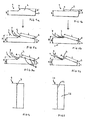
- FR2 657 079 or FR 2,766,816 is melted at around 1650 ° C in an amount such that a ribbon of glass can be laminated, ribbon in which plates 1 of final dimensions of the order of 55 cm x 60 cm and having a standard thickness h of 4 mm are cut out.
- the upper roll used for rolling has a deep recess depth for example of the order of or slightly greater than 2 mm and profile corresponding approximately to the profile of the extra thickness that is to be generated, the lower roll being as for engraved him to form pimples (not shown) on the underside of the plate.
- the excess thickness 2 is generated on the plate a few millimeters from the cutting zone (and therefore the edge of the plate obtained after cutting), and in the case of the figure 1b it is generated in contact with said cutting zone (and therefore on the edge of the plate obtained), the height h 'of the extra thickness being for example of the order of 2 mm.
- the laminated plates can be decorated, for example with the aid of enamel, or drilled for the subsequent incorporation of control elements. After cutting the plates, they can also be shaped, especially their edge 3, to avoid, for example, the presence of sharp edges that can hurt users.
- the glass plate comprises the crystal phase ⁇ quartz and / or ⁇ spodumene.
- a bevelling operation is performed on the excess thickness 2 using an inclined wheel.
- a bevel 5 of height h "corresponding to the value H - e is obtained (H being the thickness of the plate at the top of the bevel and e that at the base of the bevel, this thickness e coinciding here with the thickness of the remaining heel ), for example ranging from 1.5 to 3.5 mm and width L ranging for example from 35 to 82 mm, the ratio L / h "remaining advantageously less than 23.3 and preferably less than 22.
- the bevel present a line of ridge 4 perfectly straight (as schematized in figure 4 ) and can be extended by a flat part 6 and / or by an inclined or straight wall 7 of the excess thickness.
- a heel with a thickness e of at least 2 mm, and preferably at least 2.5 mm, is left at the end of the plate. According to destination of the plate, it can also undergo other operations during its manufacture (deformations to make eg bosses or holes ...) and can also be provided with inserts such as control elements 8 (shown in figure 3a ).
- crest line 14 of a bevel 15 of the same width L made on a similar plate 11 but without excess thickness and keeping the same minimum heel is distinguished from the crest line of the preceding plates obtained according to the invention in that that it is wavy and not perfectly straight as represented in figure 5 .
- the plates according to the invention can in particular be used with advantage to produce a new range of cooking plates for stoves or hobs.
Landscapes
- Chemical & Material Sciences (AREA)
- Engineering & Computer Science (AREA)
- Ceramic Engineering (AREA)
- Materials Engineering (AREA)
- Organic Chemistry (AREA)
- Induction Heating Cooking Devices (AREA)
- Electric Stoves And Ranges (AREA)
- Surface Treatment Of Glass (AREA)
- Baking, Grill, Roasting (AREA)
Claims (13)
- Glaskeramikplatte (1), die insbesondere zur Abdeckung von Heizelementen bestimmt ist und eine Dicke (h) im Allgemeinen von weniger als 4,5 mm aufweist, dadurch gekennzeichnet, dass sie wenigstens eine abgeschrägte Kante (5) mit einer Breite (L) von mehr als oder gleich 35 mm im Anschluss an eine Überdicke (2) aufweist.
- Platte nach Anspruch 1, dadurch gekennzeichnet, dass die abgeschrägte Kante (5) dazu bestimmt ist, ein oder mehrere Mittel zur Steuerung (8) der Heizelemente aufzunehmen.
- Platte nach einem der Ansprüche 1 oder 2, dadurch gekennzeichnet, dass die abgeschrägte Kante (5) sich an eine Überdicke (2) anschließt, wobei die Dicke der Platte (1) am höchsten Punkt der Überdicke (2) kleiner als die oder gleich der zweifache(n) Standarddicke (h) der Platte ist.
- Platte nach einem der Ansprüche 1 bis 3, dadurch gekennzeichnet, dass an der niedrigsten Stelle der abgeschrägten Kante (5) eine Dicke (e) von wenigstens 2 mm in der Platte gelassen ist.
- Platte nach einem der Ansprüche 1 bis 4, dadurch gekennzeichnet, dass die Platte (1) eine die abgeschrägte Kante oder Kanten (5) tragende Seite aufweist und dass die entgegengesetzte Seite gegenüber den abgeschrägten Kanten (5) annähernd eben, glatt oder mit Stiften versehen, bleibt.
- Platte nach einem der Ansprüche 1 bis 5, dadurch gekennzeichnet, dass das Verhältnis der Breite (L) der Abschrägung zur Höhe (h") der Abschrägung kleiner als 23,3 ist.
- Platte nach einem der Ansprüche 1 bis 6, dadurch gekennzeichnet, dass die abgeschrägte Kante (5) sich an eine Überdicke (2) anschließt, abgeschrägte Kante (5), die sich über wenigstens einen Teil der Breite der Überdicke (2) und eventuell über einen Teil der Breite der Platte außerhalb der Überdicke (2) erstreckt.
- Verfahren zum Abschrägen einer Platte (1), wie einer Glaskeramikplatte, das darin besteht, wenigstens eine Überdicke (2) an wenigstens einer Kante der Platte (1) auszubilden und wenigstens ein Abschrägen ab der Überdicke (2) vorzunehmen.
- Verfahren nach Anspruch 8, dadurch gekennzeichnet, dass die Überdicke (2) gleichzeitig mit der abgeschrägten Kante (5) beispielsweise durch einen Walzvorgang erzeugt wird.
- Verfahren nach Anspruch 8, dadurch gekennzeichnet, dass die sich an eine Überdicke (2) anschließende abgeschrägte Kante (5) in wenigstens zwei Schritten erhalten wird, wobei der erste darin besteht, eine Überdicke (2) auf der Platte, beispielsweise durch Walzen, zu erzeugen und der zweite darin besteht, ein Abschrägen ab der Überdicke (2) vorzunehmen.
- Verfahren nach einem der Ansprüche 8 bis 10, dadurch gekennzeichnet, dass die abgeschrägte Kante (5) sich auf einer Seite der Platte (1) befindet, wobei die entgegengesetzte Seite gegenüber der abgeschrägten Kante (5) annähernd eben, glatt oder mit Stiften versehen, bleibt.
- Verfahren nach Anspruch 8, dadurch gekennzeichnet, dass die Überdicke oder Überdicken (2) bei Verlassen des Ofens auf dem formbaren Vorläuferglas während des Formwalzvorganges erzeugt werden, wobei jede Platte (1) nach eventuellem Zuschneiden und eventueller Formgebung, sowie gegebenenfalls nach Verzieren, keramisiert, anschließend abgeschrägt wird oder, umgekehrt, abgeschrägt wird, bevor sie keramisiert wird, wobei das Abschrägen im Bereich der Überdicke oder Überdicken (2) erfolgt.
- Vorrichtung zum Kochen und/oder zum Halten auf hoher Temperatur, umfassend eine Glaskeramikplatte nach einem der Ansprüche 1 bis 7.
Applications Claiming Priority (3)
| Application Number | Priority Date | Filing Date | Title |
|---|---|---|---|
| FR0208291A FR2841970B1 (fr) | 2002-07-03 | 2002-07-03 | Plaque vitroceramique et son procede de fabrication |
| FR0208291 | 2002-07-03 | ||
| PCT/FR2003/001952 WO2004008807A2 (fr) | 2002-07-03 | 2003-06-25 | Plaque vitroceramique et son procede de fabrication |
Publications (2)
| Publication Number | Publication Date |
|---|---|
| EP1518444A2 EP1518444A2 (de) | 2005-03-30 |
| EP1518444B1 true EP1518444B1 (de) | 2014-08-06 |
Family
ID=29725106
Family Applications (1)
| Application Number | Title | Priority Date | Filing Date |
|---|---|---|---|
| EP03753631.5A Expired - Lifetime EP1518444B1 (de) | 2002-07-03 | 2003-06-25 | Glaskeramikplatte und verfahren zu ihrer herstellung |
Country Status (8)
| Country | Link |
|---|---|
| US (1) | US8216662B2 (de) |
| EP (1) | EP1518444B1 (de) |
| JP (4) | JP2006508318A (de) |
| CN (1) | CN100569029C (de) |
| AU (1) | AU2003271796A1 (de) |
| ES (1) | ES2519792T3 (de) |
| FR (1) | FR2841970B1 (de) |
| WO (1) | WO2004008807A2 (de) |
Families Citing this family (7)
| Publication number | Priority date | Publication date | Assignee | Title |
|---|---|---|---|---|
| DE10344439B3 (de) * | 2003-09-25 | 2005-02-10 | Schott Ag | Verfahren zum Herstellen von breit facettierten Glas-/Glaskeramikplatten und Glas-/Glaskeramikplatten mit breitem Facettenschliff |
| CA2465407C (en) * | 2004-04-28 | 2012-11-13 | Rui Resendes | Peroxide curable butyl formulations |
| DE102005036388A1 (de) * | 2005-08-03 | 2007-02-08 | Schott Ag | Kochfeld mit einer Glaskeramikplatte als Kochfläche |
| JP2008004252A (ja) * | 2006-05-26 | 2008-01-10 | Tdk Corp | 情報媒体用基板および情報媒体 |
| JP5435395B2 (ja) * | 2008-02-06 | 2014-03-05 | 日本電気硝子株式会社 | ガラス物品の製造方法 |
| DE102013102130B4 (de) * | 2013-03-05 | 2017-11-16 | Schott Ag | Glaskeramik-Kochfeld mit Noppenstruktur |
| EP3836755B1 (de) * | 2019-12-12 | 2025-06-04 | BSH Hausgeräte GmbH | Kochfeldvorrichtung |
Family Cites Families (14)
| Publication number | Priority date | Publication date | Assignee | Title |
|---|---|---|---|---|
| FR657079A (fr) | 1927-08-08 | 1929-05-16 | Mécanisme de freinage commandé par un fluide | |
| US2414162A (en) * | 1943-05-18 | 1947-01-14 | Westinghouse Electric Corp | Electric range |
| US3674983A (en) * | 1971-04-08 | 1972-07-04 | Gen Electric | Smooth surface electric cooktop |
| JPS62155493U (de) * | 1986-03-25 | 1987-10-02 | ||
| US5812332A (en) * | 1989-09-28 | 1998-09-22 | Ppg Industries, Inc. | Windshield for head-up display system |
| DE4333334C2 (de) * | 1993-09-30 | 1996-10-17 | Schott Glaswerke | Platte aus Glaskeramik als Bestandteil eines Kochgerätes |
| JP3042376B2 (ja) * | 1995-08-03 | 2000-05-15 | 松下電器産業株式会社 | 加熱調理器 |
| FR2741335B1 (fr) * | 1995-11-22 | 1998-01-16 | Corning Inc | Procede et dispositif de formage d'une feuille en un materiau vitreux, par pressage de la feuille a l'etat pateux entre des rouleaux contrarotatifs |
| DE19633706C2 (de) * | 1996-08-21 | 2000-01-13 | Bsh Bosch Siemens Hausgeraete | Glaskeramik-Kochfeld mit noppenlosem Randstreifen |
| DE19649767A1 (de) * | 1996-11-30 | 1998-06-04 | Schott Glaswerke | Anordnung zum Anbringen von Glaskeramik-Kochflächen mit einem zu einer dünnen Kante verjüngten Randbereich an einer Arbeitsplatte |
| FR2766816B1 (fr) | 1997-08-01 | 1999-08-27 | Eurokera | Plaque vitroceramique et son procede de fabrication |
| DE10041006C2 (de) * | 2000-08-22 | 2002-10-31 | Schott Glas | Glas- oder Glaskeramikscheibe mit einem Kantenschutz und Verfahren zu ihrer Herstellung |
| DE10061366A1 (de) * | 2000-12-09 | 2002-07-04 | Schott Glas | Schleifscheibe und Verfahren zum Schleifen von Flachfacetten an Glasscheiben, insbesondere an Glaskeramikscheiben |
| DE10344441A1 (de) * | 2003-09-25 | 2005-05-04 | Schott Ag | Verfahren zum Herstellen von gewalzten Glas- oder Glaskeramikplatten mit partiell umgeformten Teil-Bereichen |
-
2002
- 2002-07-03 FR FR0208291A patent/FR2841970B1/fr not_active Expired - Fee Related
-
2003
- 2003-06-25 JP JP2004520712A patent/JP2006508318A/ja not_active Withdrawn
- 2003-06-25 AU AU2003271796A patent/AU2003271796A1/en not_active Abandoned
- 2003-06-25 ES ES03753631.5T patent/ES2519792T3/es not_active Expired - Lifetime
- 2003-06-25 US US10/516,512 patent/US8216662B2/en not_active Expired - Fee Related
- 2003-06-25 CN CNB038156628A patent/CN100569029C/zh not_active Expired - Fee Related
- 2003-06-25 WO PCT/FR2003/001952 patent/WO2004008807A2/fr not_active Ceased
- 2003-06-25 EP EP03753631.5A patent/EP1518444B1/de not_active Expired - Lifetime
-
2009
- 2009-09-28 JP JP2009223078A patent/JP2010034068A/ja not_active Withdrawn
-
2012
- 2012-11-16 JP JP2012252050A patent/JP2013058492A/ja not_active Withdrawn
-
2014
- 2014-09-05 JP JP2014181017A patent/JP2015043324A/ja active Pending
Also Published As
| Publication number | Publication date |
|---|---|
| JP2015043324A (ja) | 2015-03-05 |
| FR2841970B1 (fr) | 2004-12-24 |
| US20050118382A1 (en) | 2005-06-02 |
| US8216662B2 (en) | 2012-07-10 |
| EP1518444A2 (de) | 2005-03-30 |
| CN100569029C (zh) | 2009-12-09 |
| AU2003271796A8 (en) | 2004-02-02 |
| WO2004008807A3 (fr) | 2004-04-08 |
| WO2004008807A2 (fr) | 2004-01-22 |
| JP2006508318A (ja) | 2006-03-09 |
| AU2003271796A1 (en) | 2004-02-02 |
| CN1666574A (zh) | 2005-09-07 |
| JP2013058492A (ja) | 2013-03-28 |
| ES2519792T3 (es) | 2014-11-07 |
| JP2010034068A (ja) | 2010-02-12 |
| FR2841970A1 (fr) | 2004-01-09 |
Similar Documents
| Publication | Publication Date | Title |
|---|---|---|
| EP0834044B1 (de) | Glaskeramik-kochplatte und verfahren zu ihrer herstellung | |
| FR2777559A1 (fr) | Fabrication de plaques vitroceramiques a ouverture(s) au pourtour deforme ; plaques vitroceramiques deformees | |
| EP2766184B1 (de) | Herstellung einer verbundglasscheibe | |
| EP1979278B1 (de) | Glas-keramik-platten, verfahren zu ihrer herstellung und kochtöpfe mit diesen platten | |
| EP2864266B1 (de) | Glaskeramikartikel und herstellungsverfahren | |
| EP1518444B1 (de) | Glaskeramikplatte und verfahren zu ihrer herstellung | |
| EP0826489B1 (de) | Verfahren zur Herstellung eines dekorierten Fassadenelements eines Haushaltselektrogeräts | |
| EP0930806B1 (de) | Glaskeramikkochplatte mit Erhebungen zur taktilen Orientierung | |
| FR2860225A1 (fr) | Procede de fabrication de plaques laminees de verre ou de vitroceramique comportant des zones partiellement faconnees | |
| EP1493306A1 (de) | Glas-keramik-platten, verfahren zu deren herstellung und damit ausgestattete kochoberfläche | |
| FR2778422A3 (fr) | Carreau adhesif ayant une couche de verre transparente | |
| FR2866642A1 (fr) | Procede de fabrication d'elements en vitroceramique, dispositif pour la mise en oeuvre dudit procede et elements en vitroceramique ainsi obtenus | |
| EP4126780B1 (de) | Glaskeramikartikel | |
| WO2019086789A1 (fr) | Article vitroceramique et procédé d'obtention | |
| EP3891106B1 (de) | Oberflächentexturierter glaskeramikartikel und verfahren zu seiner herstellung | |
| EP3449189B1 (de) | Glaskeramikplatte für eine arbeitsplatte oder ein möbelstück | |
| FR2860228A1 (fr) | Procede pour deformer partiellement des plaques de verre et plaque de verre ou de vitroceramique presentant des zones partiellement deformees | |
| FR3093950A1 (fr) | ARTICLE vitrocéramique | |
| FR2866872A1 (fr) | Plaque vitroceramique et son procede de fabrication | |
| FR2846074A1 (fr) | Plaque vitroceramique et son procede de fabrication | |
| EP3941885B1 (de) | Glaskeramikteil | |
| FR3108326A1 (fr) | Article vitrocéramique | |
| FR2790067A1 (fr) | Plaque en vitroceramique presentant sur sa face inferieure une structure bosselee, et procede de fabrication d'une telle plaque | |
| FR2810581A1 (fr) | Procede de realisation d'une imitation de facade metallique d'appareil electromenager | |
| BE886956A (fr) | Procede de polisage thermique d'articles en verre a dessin sculpte |
Legal Events
| Date | Code | Title | Description |
|---|---|---|---|
| PUAI | Public reference made under article 153(3) epc to a published international application that has entered the european phase |
Free format text: ORIGINAL CODE: 0009012 |
|
| 17P | Request for examination filed |
Effective date: 20041110 |
|
| AK | Designated contracting states |
Kind code of ref document: A2 Designated state(s): AT BE BG CH CY CZ DE DK EE ES FI FR GB GR HU IE IT LI LU MC NL PT RO SE SI SK TR |
|
| AX | Request for extension of the european patent |
Extension state: AL LT LV MK |
|
| RIN1 | Information on inventor provided before grant (corrected) |
Inventor name: HARMAND, HELENE Inventor name: VILATO, PABLO Inventor name: RENAULT, ALAIN Inventor name: HOBON, CAROL |
|
| DAX | Request for extension of the european patent (deleted) | ||
| RBV | Designated contracting states (corrected) |
Designated state(s): DE ES FR GB IT |
|
| GRAP | Despatch of communication of intention to grant a patent |
Free format text: ORIGINAL CODE: EPIDOSNIGR1 |
|
| INTG | Intention to grant announced |
Effective date: 20140221 |
|
| RAP1 | Party data changed (applicant data changed or rights of an application transferred) |
Owner name: EUROKERA S.N.C. |
|
| GRAS | Grant fee paid |
Free format text: ORIGINAL CODE: EPIDOSNIGR3 |
|
| GRAA | (expected) grant |
Free format text: ORIGINAL CODE: 0009210 |
|
| AK | Designated contracting states |
Kind code of ref document: B1 Designated state(s): DE ES FR GB IT |
|
| REG | Reference to a national code |
Ref country code: GB Ref legal event code: FG4D Free format text: NOT ENGLISH |
|
| REG | Reference to a national code |
Ref country code: DE Ref legal event code: R096 Ref document number: 60346597 Country of ref document: DE Effective date: 20140918 |
|
| REG | Reference to a national code |
Ref country code: ES Ref legal event code: FG2A Ref document number: 2519792 Country of ref document: ES Kind code of ref document: T3 Effective date: 20141107 |
|
| REG | Reference to a national code |
Ref country code: DE Ref legal event code: R097 Ref document number: 60346597 Country of ref document: DE |
|
| PLBE | No opposition filed within time limit |
Free format text: ORIGINAL CODE: 0009261 |
|
| STAA | Information on the status of an ep patent application or granted ep patent |
Free format text: STATUS: NO OPPOSITION FILED WITHIN TIME LIMIT |
|
| 26N | No opposition filed |
Effective date: 20150507 |
|
| GBPC | Gb: european patent ceased through non-payment of renewal fee |
Effective date: 20150625 |
|
| PG25 | Lapsed in a contracting state [announced via postgrant information from national office to epo] |
Ref country code: GB Free format text: LAPSE BECAUSE OF NON-PAYMENT OF DUE FEES Effective date: 20150625 |
|
| REG | Reference to a national code |
Ref country code: FR Ref legal event code: PLFP Year of fee payment: 14 |
|
| REG | Reference to a national code |
Ref country code: FR Ref legal event code: PLFP Year of fee payment: 15 |
|
| REG | Reference to a national code |
Ref country code: FR Ref legal event code: PLFP Year of fee payment: 16 |
|
| PGFP | Annual fee paid to national office [announced via postgrant information from national office to epo] |
Ref country code: FR Payment date: 20180625 Year of fee payment: 16 |
|
| PGFP | Annual fee paid to national office [announced via postgrant information from national office to epo] |
Ref country code: IT Payment date: 20180625 Year of fee payment: 16 Ref country code: ES Payment date: 20180702 Year of fee payment: 16 |
|
| PGFP | Annual fee paid to national office [announced via postgrant information from national office to epo] |
Ref country code: DE Payment date: 20190612 Year of fee payment: 17 |
|
| PG25 | Lapsed in a contracting state [announced via postgrant information from national office to epo] |
Ref country code: IT Free format text: LAPSE BECAUSE OF NON-PAYMENT OF DUE FEES Effective date: 20190625 |
|
| PG25 | Lapsed in a contracting state [announced via postgrant information from national office to epo] |
Ref country code: FR Free format text: LAPSE BECAUSE OF NON-PAYMENT OF DUE FEES Effective date: 20190630 |
|
| REG | Reference to a national code |
Ref country code: ES Ref legal event code: FD2A Effective date: 20201029 |
|
| REG | Reference to a national code |
Ref country code: DE Ref legal event code: R119 Ref document number: 60346597 Country of ref document: DE |
|
| PG25 | Lapsed in a contracting state [announced via postgrant information from national office to epo] |
Ref country code: ES Free format text: LAPSE BECAUSE OF NON-PAYMENT OF DUE FEES Effective date: 20190626 |
|
| PG25 | Lapsed in a contracting state [announced via postgrant information from national office to epo] |
Ref country code: DE Free format text: LAPSE BECAUSE OF NON-PAYMENT OF DUE FEES Effective date: 20210101 |