EP1517822B1 - Messung des maximalen haftungskoeffizients aus der belastungsmessung an einer reifenwulst - Google Patents
Messung des maximalen haftungskoeffizients aus der belastungsmessung an einer reifenwulst Download PDFInfo
- Publication number
- EP1517822B1 EP1517822B1 EP03735652A EP03735652A EP1517822B1 EP 1517822 B1 EP1517822 B1 EP 1517822B1 EP 03735652 A EP03735652 A EP 03735652A EP 03735652 A EP03735652 A EP 03735652A EP 1517822 B1 EP1517822 B1 EP 1517822B1
- Authority
- EP
- European Patent Office
- Prior art keywords
- tire
- tyre
- contact area
- azimuths
- bead
- Prior art date
- Legal status (The legal status is an assumption and is not a legal conclusion. Google has not performed a legal analysis and makes no representation as to the accuracy of the status listed.)
- Expired - Lifetime
Links
- 238000005259 measurement Methods 0.000 title claims abstract description 35
- 239000011324 bead Substances 0.000 title claims abstract description 34
- 238000000034 method Methods 0.000 claims abstract description 27
- 238000012546 transfer Methods 0.000 claims description 22
- 238000013528 artificial neural network Methods 0.000 claims description 7
- 238000005096 rolling process Methods 0.000 claims description 5
- 238000012360 testing method Methods 0.000 claims description 5
- 230000006870 function Effects 0.000 description 17
- 230000000694 effects Effects 0.000 description 12
- 238000013459 approach Methods 0.000 description 8
- 230000008901 benefit Effects 0.000 description 7
- 235000021183 entrée Nutrition 0.000 description 5
- 238000006073 displacement reaction Methods 0.000 description 4
- 230000006399 behavior Effects 0.000 description 2
- 230000008602 contraction Effects 0.000 description 2
- 230000007423 decrease Effects 0.000 description 2
- 238000009826 distribution Methods 0.000 description 2
- 238000011156 evaluation Methods 0.000 description 2
- 238000002513 implantation Methods 0.000 description 2
- 210000002569 neuron Anatomy 0.000 description 2
- 239000007787 solid Substances 0.000 description 2
- 241001080024 Telles Species 0.000 description 1
- 230000001133 acceleration Effects 0.000 description 1
- 238000004873 anchoring Methods 0.000 description 1
- 230000033228 biological regulation Effects 0.000 description 1
- 230000005540 biological transmission Effects 0.000 description 1
- 238000004364 calculation method Methods 0.000 description 1
- 238000013461 design Methods 0.000 description 1
- 238000010586 diagram Methods 0.000 description 1
- 230000004069 differentiation Effects 0.000 description 1
- 239000012467 final product Substances 0.000 description 1
- 230000001939 inductive effect Effects 0.000 description 1
- 238000004519 manufacturing process Methods 0.000 description 1
- 238000007620 mathematical function Methods 0.000 description 1
- 230000007246 mechanism Effects 0.000 description 1
- 238000012986 modification Methods 0.000 description 1
- 230000004048 modification Effects 0.000 description 1
- 238000012544 monitoring process Methods 0.000 description 1
- 238000012545 processing Methods 0.000 description 1
- 229920006395 saturated elastomer Polymers 0.000 description 1
- 238000000926 separation method Methods 0.000 description 1
- 238000010008 shearing Methods 0.000 description 1
Images




Classifications
-
- B—PERFORMING OPERATIONS; TRANSPORTING
- B60—VEHICLES IN GENERAL
- B60T—VEHICLE BRAKE CONTROL SYSTEMS OR PARTS THEREOF; BRAKE CONTROL SYSTEMS OR PARTS THEREOF, IN GENERAL; ARRANGEMENT OF BRAKING ELEMENTS ON VEHICLES IN GENERAL; PORTABLE DEVICES FOR PREVENTING UNWANTED MOVEMENT OF VEHICLES; VEHICLE MODIFICATIONS TO FACILITATE COOLING OF BRAKES
- B60T8/00—Arrangements for adjusting wheel-braking force to meet varying vehicular or ground-surface conditions, e.g. limiting or varying distribution of braking force
- B60T8/17—Using electrical or electronic regulation means to control braking
- B60T8/172—Determining control parameters used in the regulation, e.g. by calculations involving measured or detected parameters
-
- B—PERFORMING OPERATIONS; TRANSPORTING
- B60—VEHICLES IN GENERAL
- B60T—VEHICLE BRAKE CONTROL SYSTEMS OR PARTS THEREOF; BRAKE CONTROL SYSTEMS OR PARTS THEREOF, IN GENERAL; ARRANGEMENT OF BRAKING ELEMENTS ON VEHICLES IN GENERAL; PORTABLE DEVICES FOR PREVENTING UNWANTED MOVEMENT OF VEHICLES; VEHICLE MODIFICATIONS TO FACILITATE COOLING OF BRAKES
- B60T2210/00—Detection or estimation of road or environment conditions; Detection or estimation of road shapes
- B60T2210/10—Detection or estimation of road conditions
- B60T2210/12—Friction
Definitions
- the present invention relates to the evaluation of the adhesion of a vehicle on a roadway. It relates more particularly to the determination of adhesion characteristics between the roadway and a vehicle wheel, equipped with an elastic bandage such as an inflated tire or a non-pneumatic elastic bandage which rolls on the roadway.
- the present invention also relates to the various electronic assistance devices used for example for the anti-lock brake system of a vehicle or the anti-skid regulation of the driving wheels, the control of the trajectory of a vehicle or for other forms control or monitoring such as tire pressure. It is known that such devices reconstruct by calculation the coefficient of adhesion ( ⁇ ) of the tires on the road, without having made any measurement of the coefficient of adhesion or the forces developed in the contact of the tires on the ground. Even if these devices provide outstanding assistance and extra safety, their operation would greatly benefit from using a measured value, or estimated from actual measurements made on the tire in operation.
- the objective of the present invention is to propose an evaluation of the adhesion of a vehicle on a road surface, more specifically of its wheels or tires or elastic tires, terms considered equivalent in the context of the present invention. . It relates more particularly to the determination of adhesion characteristics between the roadway and a vehicle wheel, equipped with an elastic bandage such as an inflated tire or a non-tire elastic bandage which rolls on the roadway.
- the various electronic assistance devices mentioned above would therefore benefitfully use "real-time” indications on the conditions of adhesion likely to affect the behavior of a vehicle, especially in the case where it undergoes acceleration by effort motor or braking effort or by changing the direction of travel.
- the invention aims to provide a method of achieving this effectively.
- maximum adhesion potential means the ratio between the maximum tangential force (transverse or longitudinal or both combined) and the normal force that the wheel can undergo. In the text, it is also referred to as the "maximum adhesion coefficient" or the letter ⁇ .
- global forces means the three force components Fx, Fy and Fz applied to the center of the wheel and the self-aligning torque N around the Z axis.
- the aim is to estimate the maximum adhesion potential of the wheel, it must be determined from the measured local potential.
- the document US Patent 5864056 discloses a method for determining the coefficient of adhesion in the contact area of a tire on a roadway, in which several points are selected in the tread of the tire, as many measurements of stress variation are made at these points when the tire rolls on the road and the measurement signals are processed so as to extract said coefficient of adhesion.
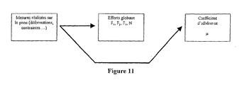
- the invention detailed here differs from these local approaches. It proposes to use a measurement of the stresses generated by the overall deformations of the tire so as to obtain information on the maximum grip potential of the wheel on the ground. Indeed, when the tire is subjected to a stress, the point of application of the forces applied in the contact area depends inter alia on the coefficient of adhesion maxi because, as soon as a part of the contact area of the wheel on the road is slipping, its contribution to tangential efforts is saturated at a level that depends on the coefficient of adhesion.
- the deformations of the tire themselves are sensitive to the displacement of this point of application. In particular, these deformations create constraints in the bead. These constraints, which are sensitive to the forces applied, are also sensitive to the displacement of the point of application of the forces in the contact area.
- the proposed method uses stress measurements in the bead (s) at certain azimuths of the tire to allow an estimation of the maximum coefficient of adhesion.
- the method requires that there be a slip zone in the contact area, whether created by a special design of the tire or by a sufficient level of stress applied to the tire.
- the invention proposes to estimate, in addition to the maximum adhesion potential, the percentage of potential used. This size indeed has the advantage of being more easily estimated in absolute value even for low stresses.
- said coefficient of adhesion ⁇ is deduced from at least 5 stress measurements made in at least one bead of the tire, at 5 fixed points in space (that is to say fixed in the frame linked to the vehicle), located at different azimuths along the circumference.
- the method of the invention is based on the observation that the forces acting between the tread of the tire and the road cause deformation of the tire sidewalls which are the cause of the occurrence of sensitive stresses and reproducible in the bead.
- the invention proposes to estimate the shear stress in the circumferential direction.
- each force applied to the tire in the contact area causes a deformation of the sidewalls of the tire which reverberates in the bead in the form of a shear stress.
- the self-aligning torque N (moment around the vertical axis) is not strictly speaking another force acting between the tread of the tire and the roadway. Rather, it is a consequence of how the Fx, Fy and Fz components are applied in the contact area. If the point of application of the resultant having components Fx, Fy and Fz is not the center of the contact area, this resultant generates a moment around Oz that is called self-alignment torque. The presence of this moment is reflected mainly by a rotation of the contact area around Oz. This effect has the effect of inducing a shear in one direction on the first sidewall and in the other direction on the second side, near the contact area.
- One of the advantages of the proposed method is to allow a separation of the contributions of each component of the applied stress, so as to allow an estimation of each of these components.
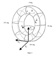
- FIG. 5 illustrates this operation by comparing a section of the tire part in the contact area without camber and camber ⁇ . This also results in a slight lateral displacement of the contact area which results in a thrust in the Y direction.
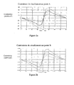
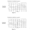
- Figures 6a and 6b show the evolution of the circumferential shear stress in the two beads. On the overloaded bead (points A), the evolution is similar to that of an increase in the load. On the other bead (points B), there is an evolution compatible with a decrease in the load carried. This evolution of the signals corresponds to a rotation of the contact area around the Ox axis.
- the azimuth ⁇ as the angle at which the shear stress in the bead is analyzed.
- the origin of the azimuth is taken opposite the center of the contact area.
- the center of the contact area therefore has the 180 ° azimuth.
- the apparent rigidity of a tire comes from both its pneumatic operation (its inflation pressure) and its structural rigidity (rigidity of its architecture).
- the measured shear stress signals also contain a pneumatic component and a structural component.
- the shear signals of a tire inflated to 2 bar and loaded at 400 daN following Z are not identical to those delivered by the same tire at 2.5 bar and loaded at 500 daN. This difference is the structural contribution and can be used to estimate the inflation pressure of the tire.
- the invention is based on the following remark:
- a simplified tire with a continuous single rib The Figures 7 and 8 represent such a tire.
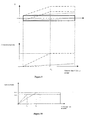
- the rib In the area of the contact area, the rib is subjected to a vertical stress which places it against the ground. We often talk about laying flat in the footprint of the tire on the ground.
- a line formed by reference points taken from the rib so that they are aligned in the ground contact pattern are then, during the rotation of the tire, included in a plane that contains said defined straight line when the points were in the contact footprint. If a drift angle is applied to the rolling tire, the plane containing the said reference points when sufficiently far from the ground contact pattern forms an angle equal to the drift angle with the reference points.
- the lateral force Fy 1 generated by the tire is equal to the integral in the contact area of the lateral stress.
- the lateral forces are the same (same area under the curve) but the point of application of the force Fy has moved.
- the measurement of the shear stress in the bead 1 on one side or on both sides of the tire can be done in any way, by an external device or a device internal to the tire.
- an external device or a device internal to the tire By way of example, it is described here to measure the circumferential shear stress in the bead 1.
- This or these sensors 3 integrated in the tire and locally measuring the circumferential shear stress of the or beads can appeal to any physical principle of measurement. It may for example be a test body 30 equipped with strain gauges 31, for example resistive. Deformation of the test body results in a modification of the resistance of the strain gauges 31 glued to its surface ( Figures 12, 13 and 14 ). The two gauges 31 placed on either side of the test body 30 then provide via a Wheatstone bridge a signal strongly related to the shear stress. If it is active, the sensor 3 can be powered either by the vehicle by remote power supply or by a battery on board the wheel or in the tire or by any other means. Everything is also possible regarding the transmission of information to the vehicle, by radio or otherwise. The sensor 3 itself must be able to provide information continuously or with a refresh rate sufficiently fast relative to the period of rotation of the wheel.
- This approach using a sensor 3 integrated in the tire has the advantage of allowing knowledge of the shear stress in the bead on one or both sides, at all azimuths of the tire since a sensor 3, driven by the tire, explores all the azimuths during a rotation of the wheel.
- An alternative to increase the accuracy or robustness of the method is to use a multi-dimensional measurement instead of a one-dimensional measurement.
- a multi-dimensional measurement instead of a one-dimensional measurement.
- the inputs of the transfer function consist of a mix of measures of one or the other or different types of constraints at different azimuths.
- exactly the same approach is used to determine the transfer function. This approach can be very interesting because in terms of the realization of the final product, it can be much simpler and less expensive to equip only one bead even if the sensor is itself more expensive to manufacture.
- tire pressure measuring systems are now available and make it possible to measure tire pressure. If such a system is available, the pressure can be used as an additional input to the transfer function as indicated by the figure 16 . Of course, other quantities can be introduced at the input of the transfer function so as to improve performance (for example and without limitation, camber, speed of the vehicle ).
- a transfer function is sought using this database, where ⁇ is the output of the transfer function.
- ⁇ is the output of the transfer function.
- the third step is to check that the transfer function obtained is working correctly in the entire desired domain, ie to verify that it is generalizable.
- the first step is to create a database containing the values of the shear stresses at the selected azimuths (or any representative value) that will represent the inputs of the transfer function, and containing p u (transfer function output) for a set of solicitations. It is possible to build such a database either using a measuring machine (the advantage is to be able to solicit the tire by independent forces Fx, Fy, Fz and to vary the coefficient of adhesion) either on a vehicle using for example a dynamometer wheel (to measure the forces) and by rolling on different grounds.
- a transfer function is sought using this database, where pu is the output of the transfer function.
- pu is the output of the transfer function.
- it is the learning phase.
- the third step is to check that the transfer function obtained is working correctly in the entire desired domain, ie to verify that it is generalizable.
- the proposed percentage has the advantage of being more easily accurately estimated in absolute size regardless of the stress, even low, applied to the tire. It is obtained directly for example by a neural network by applying the approach presented for the estimation of ⁇ .
- the figure 17 presents an example of reconstruction of the maximum adhesion potential and the percentage of potential used.
- the engine or braking torque (slip linked to Fx) and the transverse force (drift related to Fy) vary over time as well as the ground on which the vehicle rolls.
- the load Fz is imposed. When the tire load is low (low Fx and Fy simultaneously) in the vicinity of 4 s, the quality of the estimate of the maximum grip potential drops. The estimate of the percentage of potential used remains entirely correct.
Landscapes
- Engineering & Computer Science (AREA)
- Transportation (AREA)
- Mechanical Engineering (AREA)
- Tires In General (AREA)
- Motor Or Generator Current Collectors (AREA)
- Brushes (AREA)
- Investigating Strength Of Materials By Application Of Mechanical Stress (AREA)
- Regulating Braking Force (AREA)
Claims (11)
- Verfahren zum Bestimmen des Haftkoeffizienten µ auf der Aufstandsfläche eines Reifens auf einer Fahrbahn, wobei mehrere feste Punkte im Raum ausgewählt werden, die sich an verschiedenen Azimutwinkeln längs des Umfangs wenigstens in einem Wulst des Reifens befinden, ebensoviele Messungen der Beanspruchungsveränderung an diesen festen Punkten ausgeführt werden, wenn der Reifen auf der Fahrbahn rollt, und die Messsignale verarbeitet werden, um den Haftkoeffizient µ daraus zu extrahieren.
- Verfahren nach Anspruch 1, dadurch gekennzeichnet, dass der Haftkoeffizient µ aus wenigstens 5 Messungen der Scherbeanspruchungsveränderung abgeleitet wird, die wenigstens in einem Wulst des Reifens an 5 festen Punkten im Raum ausgeführt werden, die sich an verschiedenen Azimutwinkeln längs des Umfangs befinden.
- Verfahren nach Anspruch 1 oder 2, dadurch gekennzeichnet, dass die Messung der Scherbeanspruchung durch wenigstens einen in einen Wulst des Reifens integrierten Sensor ausgeführt wird, wobei das von diesem Sensor gelieferte Signal verarbeitet wird, um seinen Wert an verschiedenen Azimutwinkeln, die diesen festen Punkten entsprechen, zu entnehmen.
- Verfahren nach Anspruch 1 oder 2, dadurch gekennzeichnet, dass die Messung der Scherbeanspruchung durch ebenso viele Sensoren ausgeführt wird, wie Azimutwinkel beobachtet werden sollen, wobei sich die Sensoren außerhalb des Reifens befinden und im festen Raum angeordnet sind.
- Verfahren nach einem der Ansprüche 1 bis 4, dadurch gekennzeichnet, dass eine Messung an drei Azimutwinkeln auf jeder der beiden Flanken, bei einem Azimutwinkel, der am Anfang der Aufstandsfläche gewählt ist, bei 180° und bei einem Azimutwinkel, der am Austritt der Aufstandsfläche gewählt ist und ein Azimutwinkel ist, der zu jenem, der am Anfang verwendet wird, symmetrisch ist, ausgeführt wird.
- Verfahren nach einem der Ansprüche 1 bis 5, dadurch gekennzeichnet, dass eine Messung an sieben Azimutwinkeln auf einer einzigen Flanke ausgeführt wird, wobei sich die drei ersten Azimutwinkel am Anfang der Aufstandsfläche befinden, der Vierte sich bei 180° im Zentrum der Aufstandsfläche befindet und die drei Letzteren zu den drei Ersteren in Bezug auf das Zentrum der Aufstandsfläche symmetrisch sind.
- Verfahren nach einem der Ansprüche 1 bis 6, dadurch gekennzeichnet, dass eine Übertragungsfunktion zwischen den Messungen und dem maximalen Haftkoeffizienten durch die folgenden Schritte gebildet wird:- Erzeugen einer Datenbank, die die Scherbeanspruchungswerte an den gewählten Azimutwinkeln und die zugeordneten Werte von µ enthält, wobei die Gesamtheit der Werte experimentell gewonnen wird,- Suchen einer Übertragungsfunktion mit Hilfe dieser Datenbank, wobei µ der Ausgang der Übertragungsfunktion ist.
- Verfahren nach Anspruch 7, die ein neuronales Netz des Perzeptron-Typs mit verborgener Schicht, das als eine Approximierungseinrichtung verwendet wird, verwendet.
- Verfahren nach einem der Ansprüche 1 bis 8, dadurch gekennzeichnet, dass die Scherbeanspruchung durch die Messung der Biegung eines in den Wulst eingesetzten Prüfkörpers geschätzt wird.
- Verfahren nach einem der Ansprüche 1 bis 8, dadurch gekennzeichnet, dass die Scherbeanspruchung durch die Messung der Biegung eines Prüfkörpers mit Hilfe von Verformungslehren geschätzt wird.
- Verfahren nach einem der Ansprüche 1 bis 10, dadurch gekennzeichnet, dass der verwendete Haftpotential-Prozentsatz, der definiert ist durch

auf die folgende Weise bestimmt wird:- Erzeugen einer Datenbank, die die Werte der Scherbeanspruchungen an den gewählten Azimutwinkeln enthält, für eine Gesamtheit von Belastungen des Reifens,- Suchen einer Übertragungsfunktion mit Hilfe dieser Datenbank, wobei pu der Ausgang der Übertragungsfunktion ist und die Scherbeanspruchungswerte die Eingänge der Übertragungsfunktion sind,- Verifizieren, dass die erhaltene Übertragungsfunktion im gesamten gewünschten Bereich von Belastungen korrekt arbeitet.
Applications Claiming Priority (3)
| Application Number | Priority Date | Filing Date | Title |
|---|---|---|---|
| FR0207809 | 2002-06-24 | ||
| FR0207809A FR2841336A1 (fr) | 2002-06-24 | 2002-06-24 | Mesure du coefficient d'adherence maximal a partir de la mesure de contraintes dans un bourrelet d'un pneu |
| PCT/EP2003/006510 WO2004000620A1 (fr) | 2002-06-24 | 2003-06-20 | Mesure du coefficient d’adherence maximal a partir de la mesure de contraintes dans un bourrelet d’un pneu |
Publications (2)
| Publication Number | Publication Date |
|---|---|
| EP1517822A1 EP1517822A1 (de) | 2005-03-30 |
| EP1517822B1 true EP1517822B1 (de) | 2011-02-23 |
Family
ID=29720000
Family Applications (1)
| Application Number | Title | Priority Date | Filing Date |
|---|---|---|---|
| EP03735652A Expired - Lifetime EP1517822B1 (de) | 2002-06-24 | 2003-06-20 | Messung des maximalen haftungskoeffizients aus der belastungsmessung an einer reifenwulst |
Country Status (9)
| Country | Link |
|---|---|
| EP (1) | EP1517822B1 (de) |
| JP (1) | JP2005530649A (de) |
| KR (1) | KR20050014862A (de) |
| CN (1) | CN1288015C (de) |
| AT (1) | ATE499255T1 (de) |
| AU (1) | AU2003237963A1 (de) |
| DE (1) | DE60336135D1 (de) |
| FR (1) | FR2841336A1 (de) |
| WO (1) | WO2004000620A1 (de) |
Families Citing this family (15)
| Publication number | Priority date | Publication date | Assignee | Title |
|---|---|---|---|---|
| JP4653435B2 (ja) * | 2004-07-26 | 2011-03-16 | 住友電気工業株式会社 | タイヤに作用する力の検出装置 |
| EP1763663A1 (de) | 2004-06-30 | 2007-03-21 | Societe de Technologie Michelin | System zur berechnung des maximalen haftkoeffizienten mittels belastungsmessung bei einem reifenprofil |
| KR100725864B1 (ko) * | 2005-11-15 | 2007-06-08 | 한국타이어 주식회사 | 타이어의 전단변형 측정장치 |
| JP4914179B2 (ja) * | 2006-11-07 | 2012-04-11 | 住友ゴム工業株式会社 | 空気入りタイヤ、及びそれに作用する力の検出方法 |
| FR2909946B1 (fr) * | 2006-12-13 | 2010-09-17 | Soc Tech Michelin | Procede d'estimation d'un risque de defaut de liaison au sol d'un vehicule automobile |
| WO2009003846A1 (fr) * | 2007-07-04 | 2009-01-08 | Societe De Technologie Michelin | Procede de detection d'un glissement local d'un pain de sculpture et application à l'estimation de l'adherence maximale du pneumatique. |
| FR2918454B1 (fr) * | 2007-07-04 | 2009-10-09 | Michelin Soc Tech | Procede d'estimation de l'adherence globale maximale d'un pneumatique. |
| FR2918478B1 (fr) * | 2007-07-04 | 2009-08-21 | Michelin Soc Tech | Procede d'estimation de la marge d'adherence disponible d'un pneumatique en roulage. |
| ITTO20110255A1 (it) * | 2011-03-24 | 2012-09-25 | Bridgestone Corp | Metodo per determinare le sollecitazioni che devono venire applicate ad un pneumatico durante una prova di durata al coperto svolta in un banco di prova |
| CN103863278B (zh) * | 2014-03-12 | 2016-05-18 | 刘振国 | 车辆防滑转与防抱死系统 |
| DE102016214065A1 (de) * | 2016-07-29 | 2018-02-01 | Zf Friedrichshafen Ag | Bestimmung einer maximalen Kraftschlussgrenze |
| JP6775753B2 (ja) * | 2018-01-10 | 2020-10-28 | Azapa株式会社 | 路面摩擦係数の推定方法、推定システム及び推定プログラム |
| CN111366383B (zh) * | 2020-04-16 | 2021-07-06 | 东风汽车集团有限公司 | 汽车整车为试验载体的轮胎与路面最大附着系数测试方法 |
| CN114166659B (zh) * | 2021-12-07 | 2024-04-12 | 长沙学院 | 一种废旧轮胎-土竖直界面剪切特性测试装置 |
| CN115683666B (zh) * | 2022-10-20 | 2025-09-30 | 中策橡胶集团股份有限公司 | 轮胎接地面滑移区与粘着区的识别及可视化方法、应用和程序产品 |
Family Cites Families (12)
| Publication number | Priority date | Publication date | Assignee | Title |
|---|---|---|---|---|
| US3852993A (en) * | 1972-08-01 | 1974-12-10 | M Bronovets | Method of determining the frictional and mechanical properties of materials and a device for the realization thereof |
| WO1985002592A1 (fr) * | 1983-12-16 | 1985-06-20 | Robert Bosch Gmbh | Procede pour determiner une valeur de glissement optimale |
| DE3667945D1 (de) * | 1985-06-04 | 1990-02-08 | Bosch Gmbh Robert | Verfahren zur einstellung eines optimierten bremsschlupfs. |
| EP0363570B1 (de) * | 1988-10-13 | 1996-02-21 | Japan Electronics Industry, Ltd. | Strassenoberflächen-Reibungsaufnehmer und Strassenoberflächen-Reibungskoeffizienten-Aufnehmer und Fahrzeug-Blockierschutz-Bremsanlage |
| DE4435448B4 (de) * | 1993-10-13 | 2007-10-11 | Volkswagen Ag | Verfahren zur permanenten Ermittlung des Fahrbahnreibwerts |
| DE19646235C1 (de) * | 1996-11-08 | 1998-04-02 | Continental Ag | Fahrzeugreifen mit einer Einrichtung zur Bestimmung der Kraftschlußverhältnisse |
| US5864056A (en) * | 1998-02-17 | 1999-01-26 | Bell; Larry D. | Method and apparatus for monitoring the coefficient of friction between a tire and rolling surface, particularly to provide the vehicle operator with coefficient of friction, tire tread wear out and skid warning indications |
| ATE381004T1 (de) * | 1998-04-07 | 2007-12-15 | Pirelli | Verfahren zur bestimmung des strassenverhaltens eines fahrzeugreifens |
| DE69924464T2 (de) * | 1998-09-07 | 2006-03-16 | Bridgestone Corp. | Methode zur voraussage der leistungsfähigkeit eines reifens |
| US7267148B2 (en) * | 1999-08-10 | 2007-09-11 | Michelin Recherche Et Technique S.A. | Measurement of adherence between a vehicle wheel and the roadway |
| JP4272317B2 (ja) * | 1999-10-25 | 2009-06-03 | 株式会社ブリヂストン | タイヤ設計方法、タイヤ用加硫金型設計方法、タイヤ用加硫金型製造方法、空気入りタイヤの製造方法、タイヤ設計プログラムを記録した記録媒体 |
| EP1230115B1 (de) * | 1999-11-18 | 2005-02-16 | PIRELLI PNEUMATICI Società per Azioni | Methode und vorrichtung zur momentanen überwachung eines reifenverhaltens während der fahrt eines kraftfahrzeuges |
-
2002
- 2002-06-24 FR FR0207809A patent/FR2841336A1/fr not_active Withdrawn
-
2003
- 2003-06-20 DE DE60336135T patent/DE60336135D1/de not_active Expired - Lifetime
- 2003-06-20 KR KR10-2004-7020409A patent/KR20050014862A/ko not_active Withdrawn
- 2003-06-20 AU AU2003237963A patent/AU2003237963A1/en not_active Abandoned
- 2003-06-20 WO PCT/EP2003/006510 patent/WO2004000620A1/fr not_active Ceased
- 2003-06-20 CN CNB038149532A patent/CN1288015C/zh not_active Expired - Fee Related
- 2003-06-20 AT AT03735652T patent/ATE499255T1/de not_active IP Right Cessation
- 2003-06-20 EP EP03735652A patent/EP1517822B1/de not_active Expired - Lifetime
- 2003-06-20 JP JP2004514807A patent/JP2005530649A/ja active Pending
Also Published As
| Publication number | Publication date |
|---|---|
| KR20050014862A (ko) | 2005-02-07 |
| ATE499255T1 (de) | 2011-03-15 |
| DE60336135D1 (de) | 2011-04-07 |
| AU2003237963A1 (en) | 2004-01-06 |
| CN1288015C (zh) | 2006-12-06 |
| JP2005530649A (ja) | 2005-10-13 |
| FR2841336A1 (fr) | 2003-12-26 |
| WO2004000620A1 (fr) | 2003-12-31 |
| EP1517822A1 (de) | 2005-03-30 |
| CN1662408A (zh) | 2005-08-31 |
Similar Documents
| Publication | Publication Date | Title |
|---|---|---|
| EP1476339B1 (de) | Schätzung des maximalen haftungskoeffiezienten anhand der kräfte und des moments der selbstausrichtung in der aufstandsfläche eines reifens | |
| EP1417465B1 (de) | Verfahren zur bestimmung der eigenschaften eines reifens aus belastungen | |
| EP1517822B1 (de) | Messung des maximalen haftungskoeffizients aus der belastungsmessung an einer reifenwulst | |
| EP3083360B1 (de) | Schätzung des haftpotenzials durch beurteilung des rollradius | |
| EP1327131B1 (de) | Verfahren und system oder zentrale zur überwachung des reifenzustandes und zur feststellung der anwesenheit von ketten oder spikes am fahrzeug | |
| EP1476338B1 (de) | Maximalreibwertermittlung anhand der messung der umfangausdehnung in einer reifenseitenwand | |
| EP1977942B1 (de) | Verfahren zur Erkennung und Abschätzung eines Aquaplaning-Phänomens eines Reifens auf einer nassen Fahrbahn | |
| EP1417470A1 (de) | Verfahren zur bestimmung der beanspruchungskomponenten auf einen luftreifen und ein selbst-ausrichtungspaar | |
| EP2758257B1 (de) | Verfahren zur schätzung des rollwiderstandes eines fahrzeugrades | |
| EP2408651B1 (de) | Verfahren zur bestimmung eines radhaftungskoeffizienten durch gleichzeitiges festklemmen | |
| WO2001090714A2 (fr) | Methode de determination de composantes d'efforts subis par un pneumatique | |
| EP1763663A1 (de) | System zur berechnung des maximalen haftkoeffizienten mittels belastungsmessung bei einem reifenprofil | |
| EP1953052B1 (de) | Verfahren zur Quantifizierung der Verwendung einer potenziellen maximalen Bodenhaftung eines Reifens | |
| US7398146B2 (en) | Measurement of the maximum adhesion coefficient by measuring stress in a bead of a tire | |
| FR2915802A1 (fr) | Procede et systeme de determination d'adherence pour vehicule automobile | |
| EP1560086B1 (de) | Reifentestsysrem mit einem Algorithmus der die durchschnittliche Steigung der Variation eines Parameters, der von einem anderen abhängt, vergleicht | |
| FR2924661A1 (fr) | Procede d'estimation d'un angle de derive d'un pneumatique. |
Legal Events
| Date | Code | Title | Description |
|---|---|---|---|
| PUAI | Public reference made under article 153(3) epc to a published international application that has entered the european phase |
Free format text: ORIGINAL CODE: 0009012 |
|
| 17P | Request for examination filed |
Effective date: 20050124 |
|
| AK | Designated contracting states |
Kind code of ref document: A1 Designated state(s): AT BE BG CH CY CZ DE DK EE ES FI FR GB GR HU IE IT LI LU MC NL PT RO SE SI SK TR |
|
| AX | Request for extension of the european patent |
Extension state: AL LT LV MK |
|
| DAX | Request for extension of the european patent (deleted) | ||
| GRAP | Despatch of communication of intention to grant a patent |
Free format text: ORIGINAL CODE: EPIDOSNIGR1 |
|
| RIC1 | Information provided on ipc code assigned before grant |
Ipc: B60T 8/172 20060101ALI20100716BHEP Ipc: G01M 17/02 20060101ALI20100716BHEP Ipc: B60T 8/00 20060101AFI20100716BHEP |
|
| GRAS | Grant fee paid |
Free format text: ORIGINAL CODE: EPIDOSNIGR3 |
|
| GRAA | (expected) grant |
Free format text: ORIGINAL CODE: 0009210 |
|
| AK | Designated contracting states |
Kind code of ref document: B1 Designated state(s): AT BE BG CH CY CZ DE DK EE ES FI FR GB GR HU IE IT LI LU MC NL PT RO SE SI SK TR |
|
| REG | Reference to a national code |
Ref country code: GB Ref legal event code: FG4D Free format text: NOT ENGLISH |
|
| REG | Reference to a national code |
Ref country code: CH Ref legal event code: EP |
|
| REG | Reference to a national code |
Ref country code: IE Ref legal event code: FG4D Free format text: LANGUAGE OF EP DOCUMENT: FRENCH |
|
| REF | Corresponds to: |
Ref document number: 60336135 Country of ref document: DE Date of ref document: 20110407 Kind code of ref document: P |
|
| REG | Reference to a national code |
Ref country code: DE Ref legal event code: R096 Ref document number: 60336135 Country of ref document: DE Effective date: 20110407 |
|
| REG | Reference to a national code |
Ref country code: NL Ref legal event code: VDEP Effective date: 20110223 |
|
| PG25 | Lapsed in a contracting state [announced via postgrant information from national office to epo] |
Ref country code: GR Free format text: LAPSE BECAUSE OF FAILURE TO SUBMIT A TRANSLATION OF THE DESCRIPTION OR TO PAY THE FEE WITHIN THE PRESCRIBED TIME-LIMIT Effective date: 20110524 Ref country code: SE Free format text: LAPSE BECAUSE OF FAILURE TO SUBMIT A TRANSLATION OF THE DESCRIPTION OR TO PAY THE FEE WITHIN THE PRESCRIBED TIME-LIMIT Effective date: 20110223 Ref country code: PT Free format text: LAPSE BECAUSE OF FAILURE TO SUBMIT A TRANSLATION OF THE DESCRIPTION OR TO PAY THE FEE WITHIN THE PRESCRIBED TIME-LIMIT Effective date: 20110623 Ref country code: ES Free format text: LAPSE BECAUSE OF FAILURE TO SUBMIT A TRANSLATION OF THE DESCRIPTION OR TO PAY THE FEE WITHIN THE PRESCRIBED TIME-LIMIT Effective date: 20110603 |
|
| PG25 | Lapsed in a contracting state [announced via postgrant information from national office to epo] |
Ref country code: FI Free format text: LAPSE BECAUSE OF FAILURE TO SUBMIT A TRANSLATION OF THE DESCRIPTION OR TO PAY THE FEE WITHIN THE PRESCRIBED TIME-LIMIT Effective date: 20110223 Ref country code: AT Free format text: LAPSE BECAUSE OF FAILURE TO SUBMIT A TRANSLATION OF THE DESCRIPTION OR TO PAY THE FEE WITHIN THE PRESCRIBED TIME-LIMIT Effective date: 20110223 Ref country code: BG Free format text: LAPSE BECAUSE OF FAILURE TO SUBMIT A TRANSLATION OF THE DESCRIPTION OR TO PAY THE FEE WITHIN THE PRESCRIBED TIME-LIMIT Effective date: 20110523 Ref country code: SI Free format text: LAPSE BECAUSE OF FAILURE TO SUBMIT A TRANSLATION OF THE DESCRIPTION OR TO PAY THE FEE WITHIN THE PRESCRIBED TIME-LIMIT Effective date: 20110223 Ref country code: NL Free format text: LAPSE BECAUSE OF FAILURE TO SUBMIT A TRANSLATION OF THE DESCRIPTION OR TO PAY THE FEE WITHIN THE PRESCRIBED TIME-LIMIT Effective date: 20110223 Ref country code: CY Free format text: LAPSE BECAUSE OF FAILURE TO SUBMIT A TRANSLATION OF THE DESCRIPTION OR TO PAY THE FEE WITHIN THE PRESCRIBED TIME-LIMIT Effective date: 20110223 |
|
| REG | Reference to a national code |
Ref country code: IE Ref legal event code: FD4D |
|
| PG25 | Lapsed in a contracting state [announced via postgrant information from national office to epo] |
Ref country code: DK Free format text: LAPSE BECAUSE OF FAILURE TO SUBMIT A TRANSLATION OF THE DESCRIPTION OR TO PAY THE FEE WITHIN THE PRESCRIBED TIME-LIMIT Effective date: 20110223 Ref country code: EE Free format text: LAPSE BECAUSE OF FAILURE TO SUBMIT A TRANSLATION OF THE DESCRIPTION OR TO PAY THE FEE WITHIN THE PRESCRIBED TIME-LIMIT Effective date: 20110223 Ref country code: IE Free format text: LAPSE BECAUSE OF FAILURE TO SUBMIT A TRANSLATION OF THE DESCRIPTION OR TO PAY THE FEE WITHIN THE PRESCRIBED TIME-LIMIT Effective date: 20110223 |
|
| PG25 | Lapsed in a contracting state [announced via postgrant information from national office to epo] |
Ref country code: SK Free format text: LAPSE BECAUSE OF FAILURE TO SUBMIT A TRANSLATION OF THE DESCRIPTION OR TO PAY THE FEE WITHIN THE PRESCRIBED TIME-LIMIT Effective date: 20110223 Ref country code: CZ Free format text: LAPSE BECAUSE OF FAILURE TO SUBMIT A TRANSLATION OF THE DESCRIPTION OR TO PAY THE FEE WITHIN THE PRESCRIBED TIME-LIMIT Effective date: 20110223 Ref country code: RO Free format text: LAPSE BECAUSE OF FAILURE TO SUBMIT A TRANSLATION OF THE DESCRIPTION OR TO PAY THE FEE WITHIN THE PRESCRIBED TIME-LIMIT Effective date: 20110223 |
|
| PLBE | No opposition filed within time limit |
Free format text: ORIGINAL CODE: 0009261 |
|
| STAA | Information on the status of an ep patent application or granted ep patent |
Free format text: STATUS: NO OPPOSITION FILED WITHIN TIME LIMIT |
|
| BERE | Be: lapsed |
Owner name: SOC. DE TECHNOLOGIE MICHELIN Effective date: 20110630 Owner name: MICHELIN RECHERCHE ET TECHNIQUE S.A. Effective date: 20110630 |
|
| REG | Reference to a national code |
Ref country code: CH Ref legal event code: PL |
|
| 26N | No opposition filed |
Effective date: 20111124 |
|
| GBPC | Gb: european patent ceased through non-payment of renewal fee |
Effective date: 20110620 |
|
| REG | Reference to a national code |
Ref country code: DE Ref legal event code: R097 Ref document number: 60336135 Country of ref document: DE Effective date: 20111124 |
|
| PG25 | Lapsed in a contracting state [announced via postgrant information from national office to epo] |
Ref country code: BE Free format text: LAPSE BECAUSE OF NON-PAYMENT OF DUE FEES Effective date: 20110630 |
|
| PG25 | Lapsed in a contracting state [announced via postgrant information from national office to epo] |
Ref country code: LI Free format text: LAPSE BECAUSE OF NON-PAYMENT OF DUE FEES Effective date: 20110630 Ref country code: CH Free format text: LAPSE BECAUSE OF NON-PAYMENT OF DUE FEES Effective date: 20110630 |
|
| PG25 | Lapsed in a contracting state [announced via postgrant information from national office to epo] |
Ref country code: IT Free format text: LAPSE BECAUSE OF FAILURE TO SUBMIT A TRANSLATION OF THE DESCRIPTION OR TO PAY THE FEE WITHIN THE PRESCRIBED TIME-LIMIT Effective date: 20110223 |
|
| PG25 | Lapsed in a contracting state [announced via postgrant information from national office to epo] |
Ref country code: GB Free format text: LAPSE BECAUSE OF NON-PAYMENT OF DUE FEES Effective date: 20110620 |
|
| PG25 | Lapsed in a contracting state [announced via postgrant information from national office to epo] |
Ref country code: MC Free format text: LAPSE BECAUSE OF NON-PAYMENT OF DUE FEES Effective date: 20110630 |
|
| PG25 | Lapsed in a contracting state [announced via postgrant information from national office to epo] |
Ref country code: LU Free format text: LAPSE BECAUSE OF NON-PAYMENT OF DUE FEES Effective date: 20110620 |
|
| PG25 | Lapsed in a contracting state [announced via postgrant information from national office to epo] |
Ref country code: TR Free format text: LAPSE BECAUSE OF FAILURE TO SUBMIT A TRANSLATION OF THE DESCRIPTION OR TO PAY THE FEE WITHIN THE PRESCRIBED TIME-LIMIT Effective date: 20110223 |
|
| PG25 | Lapsed in a contracting state [announced via postgrant information from national office to epo] |
Ref country code: HU Free format text: LAPSE BECAUSE OF FAILURE TO SUBMIT A TRANSLATION OF THE DESCRIPTION OR TO PAY THE FEE WITHIN THE PRESCRIBED TIME-LIMIT Effective date: 20110223 |
|
| REG | Reference to a national code |
Ref country code: FR Ref legal event code: PLFP Year of fee payment: 14 |
|
| REG | Reference to a national code |
Ref country code: FR Ref legal event code: PLFP Year of fee payment: 15 |
|
| REG | Reference to a national code |
Ref country code: FR Ref legal event code: PLFP Year of fee payment: 16 |
|
| PGFP | Annual fee paid to national office [announced via postgrant information from national office to epo] |
Ref country code: DE Payment date: 20180625 Year of fee payment: 16 |
|
| PGFP | Annual fee paid to national office [announced via postgrant information from national office to epo] |
Ref country code: FR Payment date: 20180626 Year of fee payment: 16 |
|
| REG | Reference to a national code |
Ref country code: DE Ref legal event code: R119 Ref document number: 60336135 Country of ref document: DE |
|
| PG25 | Lapsed in a contracting state [announced via postgrant information from national office to epo] |
Ref country code: DE Free format text: LAPSE BECAUSE OF NON-PAYMENT OF DUE FEES Effective date: 20200101 |
|
| PG25 | Lapsed in a contracting state [announced via postgrant information from national office to epo] |
Ref country code: FR Free format text: LAPSE BECAUSE OF NON-PAYMENT OF DUE FEES Effective date: 20190630 |