EP1517279A2 - Vorrichtung zum Anhalten eines Motors, die verwendbar in einem Spielautomaten ist, und Spielautomat mit einer solchen Vorrichtung - Google Patents
Vorrichtung zum Anhalten eines Motors, die verwendbar in einem Spielautomaten ist, und Spielautomat mit einer solchen Vorrichtung Download PDFInfo
- Publication number
- EP1517279A2 EP1517279A2 EP04022041A EP04022041A EP1517279A2 EP 1517279 A2 EP1517279 A2 EP 1517279A2 EP 04022041 A EP04022041 A EP 04022041A EP 04022041 A EP04022041 A EP 04022041A EP 1517279 A2 EP1517279 A2 EP 1517279A2
- Authority
- EP
- European Patent Office
- Prior art keywords
- motor
- stop
- reel
- main cpu
- voltage value
- Prior art date
- Legal status (The legal status is an assumption and is not a legal conclusion. Google has not performed a legal analysis and makes no representation as to the accuracy of the status listed.)
- Withdrawn
Links
Images


Classifications
-
- G—PHYSICS
- G07—CHECKING-DEVICES
- G07F—COIN-FREED OR LIKE APPARATUS
- G07F17/00—Coin-freed apparatus for hiring articles; Coin-freed facilities or services
- G07F17/32—Coin-freed apparatus for hiring articles; Coin-freed facilities or services for games, toys, sports, or amusements
- G07F17/3202—Hardware aspects of a gaming system, e.g. components, construction, architecture thereof
- G07F17/3204—Player-machine interfaces
- G07F17/3211—Display means
- G07F17/3213—Details of moving display elements, e.g. spinning reels, tumbling members
Definitions
- the present invention relates to a motor stop control device utilized in a reel-type gaming machine and a gaming machine using the motor stop control device, the motor stop control device having a motor as a drive source of a reel on which a plurality of symbols are formed and stopping the motor corresponding to a stop instruction from an external.
- a symbol variable rotation device for a reel-type gaming machine for example, a Japanese Pachi-slot machine
- a reel directly connected to a rotor of a stepping motor (abbreviated as "direct drive manner") as shown in Japanese Unexamined Publication No. 10-71240.
- direct drive manner a reel directly connected to a rotor of a stepping motor
- all phases of the stepping motor are excited and a detent torque occurs in the stepping motor, thereby smooth stop of the reel is realized.
- the assembler in order to make the stop position of the stepping motor more precise, in other words, in order that imbalance of the detent torque does not affect the stop position, the assembler has to prepare the inertia of the reel by attaching a weight to the reel which is attached to the stepping motor and to prepare balance between the detent torque and the inertia in the combination of the stepping motor and the reel. Accordingly, there is a problem that cost of the stepping motor is further increased.
- the present invention has been done to dissolve the above problems and has an object to provide a motor stop control device by which the reel can be smoothly stopped without depending upon a large detent torque and preciseness of the stop position of the reel can be raised without increasing cost of the stepping motor due to imbalance of the detent torque.
- a motor stop control device utilizable for a gaming machine with a reel on which a plurality of symbols are formed, the motor stop control device having a motor with a plurality of excitation phases to rotate the reel and a motor stop controller for stopping the motor based on a stop instruction, wherein the motor stop controller decreases a first voltage value added to the motor rotating at a constant speed to a second voltage value lower than the first voltage value when the stop instruction occurs and executes a stop control process of the motor by 2-phase excitation.
- the motor stop controller decreases a first voltage value added to the motor rotating at a constant speed to a second voltage value lower than the first voltage value when the stop instruction occurs and executes a stop control process of the motor by 2-phase excitation.
- the reel can be smoothly stopped without depending upon the detent torque and preciseness of a stop position of the reel can be raised without increasing cost due to imbalance of the detent torque.
- a gaming machine comprising:
- the motor stop controller in the motor stop control device decreases a first voltage value added to the motor rotating at a constant speed to a second voltage value lower than the first voltage value when the stop instruction occurs and executes a stop control process of the motor by 2-phase excitation.
- the reel can be smoothly stopped without depending upon the detent torque and preciseness of a stop position of the reel can be raised without increasing cost due to imbalance of the detent torque.
- the reel can be smoothly stopped without depending upon the large detent torque and preciseness of the reel stop position can be raised without increasing cost thereof due to imbalance of the detent torque.
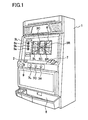
- Fig. 1 is a perspective view of a reel-type gaming machine according to the embodiment.
- Fig. 1 in front of a cabinet forming a whole construction of the reel-type gaming machine 1, three panel display windows 5L, 5C, 5R are formed. Reels 3L, 3C, 3R constructing a reel unit are seen and recognized through the panel display windows 5L, 5C, 5R, respectively. And on the panel display windows 5L, 5C, 5R, three pay lines 6 are described along three horizontal directions and two pay lines 6 are described along two oblique directions. These pay lines 6 are made effective according to the number of coins inserted through an insertion slot 7 and the number of pay lines 6 are determined.
- Each of the reels 3L, 3C, 3R starts to rotate when a player inserts coins in the insertion slot 7 and operates a start lever 9. And when the player presses stop buttons 7L, 7C, 7R arranged corresponding to the reels 3L, 3C, 3R respectively, rotation of the reels 3L, 3C, 3R is stopped. Further, based on a symbol combination of each of reels 3L, 3C, 3R which are seen and recognized through each of the panel display windows 5L, 5C, 5R when rotation of the reels 3L, 3C, 3R is stopped, a winning mode is determined. And when winning is obtained, coins the number of which corresponds to the winning mode are paid out to a coin tray 8.
- the left panel display window 5L (merely abbreviated as “the panel display window 5" hereinafter), the left reel 3L (merely abbreviated as “the reel 3” hereinafter), the left support plate 80L (merely abbreviated as “the support plate 80 hereinafter), the left stepping motor 49L (merely abbreviated as “the stepping motor 49 hereinafter), among three panel display windows 5L, 5C, 5R, three reels 3L, 3C, 3R, three support plates 80L, 80C, 80R, three stepping motors 49L, 49C, 49R, the other panel display windows 5C, 5R, the other reels 3C, 3R, the other support plates 80C, 80R, the other stepping motors 49C, 49R have the same construction as those of the panel display window 5L, the reel 3L, the support plate 80L, the stepping motor 49L, so long as explanation is not especially referred.
- Fig. 2 is a perspective view showing the construction of the reel unit arranged within the panel display windows 5L, 5C, 5R.
- the reel 3 is supported to the frame 40 through the support plate 80.
- a reel strip 34 is adhered.
- a plurality of symbols are described.
- the stepping motor 49 is arranged and the reel 3 is rotated based on that the stepping motor 49 is driven.
- a drive shaft of the stepping motor 49 according to the embodiment is directly pressed in a center hole of the reel 3 (direct drive manner).
- Fig. 3 is an explanatory view showing a construction of the reel 3.
- a lamp case 51 is arranged in the reel drum 43 positioned behind the reel strip 34.
- a back lamp 52a is arranged in each of three parts formed in the lamp case 51.
- the back lamp 52a is constructed from a full-color LED (Light-emitting diode) capable of emitting large light quantity, and is assembled on a circuit board 53.
- This circuit board 53 is arranged behind the lamp case 51.
- a photosensor 54 is arranged on the support plate 80.
- the photosensor 54 detects that a sensor plate 50 formed in the reel drum 43 passes the photosensor 54 according to rotation of the reel drum 43.
- Each of the back lamps 52a is controlled so as to turn on and off by a lamp drive circuit 45. Based on that each of the back lamps 52a is turned on, three symbols, which are positioned in front of the back lamps 52a, among plural symbols described on the reel strip 34, are independently illuminated from the behind thereof. Thereby, three symbols are projected on each of the panel display windows 5L, 5C, 5R.
- each of the back lamps 52a is independently arranged in each of three parts partitioned by three partition walls 51a, the partition walls 51a may not be formed as shown in Fig. 3B.
- the partition walls 51a may not be formed as shown in Fig. 3B.
- Fig. 4 is a block diagram indicating an electrical construction of the reel-type gaming machine 1, including the motor stop control device.
- the motor stop control device is provided with the stepping motor 49, as the drive source of the reel 3 having a plurality of symbols, and drives or stops the stepping motor 49 corresponding to an instruction command (for example, press of the stop buttons 71, 7C, 7R) transmitted from an external.
- an instruction command for example, press of the stop buttons 71, 7C, 7R
- a main CPU 31 functioning as a main controller for mainly controlling and calculating
- a main ROM 32 for storing programs and various data
- a main RAM 33 utilized for data reading and writing
- a random number generator (not shown) for generating predetermined random number values.
- Input parts such as a start switch 6S for detecting operation of the start lever 9, a reel stop signal circuit 46 for detecting operation of the stop buttons 7L, 7C, 7R, an input part 2 including BET switches 11 ⁇ 13 for betting credited coins by pressing thereof and output parts such as a motor drive circuit 39, a lamp drive circuit 45, a hopper drive circuit 41 and a display drive circuit 48 are connected to the main CPU 31.
- the main CPU 31 functions as the winning combination determination device for determining (conducting the lottery process) a predetermined symbol combination as the winning combination. Concretely, the main CPU 31 determines the predetermined symbol combination (for example, the symbol combination of "BELLS") as the winning combination when operation of the start lever 9 is detected by the start switch 6S.
- the predetermined symbol combination for example, the symbol combination of "BELLS"
- the main CPU 31 functions as a game value giving device for giving a specific game value to the player in a case that a specific winning mode (for example, the winning combination of "Replay-Replay-Replay” and the like) is stopped and displayed on the reel 3 based on that the determined winning combination is a specific winning combination (for example, the winning combination of "BB", "RB").
- a specific winning mode for example, the winning combination of "Replay-Replay-Replay” and the like
- the main CPU 31 drops the voltage value added to the stepping motor 49 which is rotating at a constant speed to a lower voltage value than such voltage value and executes stop control (reel stop control process) of the stepping motor 49 by 2-phase excitation.
- stop control stop control process
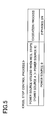
- Fig. 5 is an explanatory view showing the reel stop control process.
- the reel stop control process includes the drive power source selection process for the stepping motor 49 which is utilized when the reel 3 is stopped and the excitation process corresponding the process which is done till the reel 3 is completely stopped from termination of the stop process shown in Fig 6.
- This stop process shown in Fig. 6 means the process which is done till the excitation process is started after any one of the stop buttons 7 is pressed.
- the stop process includes the symbol process in which the draw-in process that the main CPU 31 draws the predetermined symbols internally won in the pay line or the slide process that the main CPU 31 slides the predetermined number of symbols so that the predetermined winning combination do not stop along the pay line is done till just before the reel 3 is stopped at the target stop position after the stop buttons 7 are pressed.
- the drive power source is selected when the stop process is terminated.
- Fig. 6 is an explanatory view showing a timing chart of the reel stop control process.
- Fig. 6A is an explanatory view indicating pulses in each phase, the pulses being transmitted from the main CPU 31 to the motor drive circuit 39 during the stop process and the excitation process.
- Each of the control signals 1-1 to 1-4 corresponds to a current running to the bases of the transistors TR1 to TR4 in the motor drive circuit 39 mentioned later.
- Fig. 6B is an explanatory view indicating the rotation speed of the reel 3 against time when the motor drive circuit 39 drives the stepping motor 49 based on the pulses in each phase received from the main CPU 31.
- the time indicated in Fig. 6B corresponds to the time indicated in Fig. 6A.
- the main CPU 31 changes the power source A (for example, 12V) utilized for the stepping motor 49 rotating at the constant speed to the power source B (for example, 5V) lower than the power source A, at the time that the stop process is terminated (drive power source change process). Thereafter, the main CPU 31 executes the stop control of the stepping motor 49 by 2-phase excitation.
- the power source A for example, 12V
- the power source B for example, 5V
- the main CPU 31 executes the stop process including the drive power source change process. And the main CPU 31 executes the excitation process by 2-phase excitation, thereafter the reel 3 is stopped.
- the main CPU 31 for example, outputs pulses (control signal 1-3 and the control signal 1-4) to the bases of the transistors TR3 and TR4 arranged in the motor drive circuit 39 in order to excite the C-phase and the D-phase after the stop process is terminated.
- the transistors TR3 and TR4 for example, excite the C-phase and the D-phase (2-phase excitation) for only a predetermined time interval. Based on that this excitation process is continued for the predetermined time interval, the stepping motor 49 is completely stopped.
- the line described between the stop process completion and the target stop position does not depend upon the detent torque different from the stop process conventionally done only by all phase excitation, therefore the target stop position is not fluctuated.
- the stepping motor 49 does not depend upon the detent torque with imbalance based on that the above drive power source change process is executed and the excitation process is executed by 2-phase excitation.
- the power source is changed to the power source B in which the voltage value added to each phase (L1 to L4) is lower than that in the power source A, thereby the current value running in each phase becomes lower than that in the power source A. Accordingly, corresponding to that the current value running in the excitation phases of the stepping motor 49 becomes lower, the excitation process is executed and the rotation speed of the reel 3 is decreased. Thus, since the drive power source change process and the excitation process are executed, the reel 3 is smoothly stopped by a smaller braking force than the detent torque by the power source A.
- the motor drive circuit 39 drives or stops the stepping motor 49 based on commands from the main CPU 31.
- the stepping motor 49 is 4-phase motor and has four drive coils through A-phase to D-phase.
- each phase is defined so as to stand in order A-phase, B-phase, C-phase and D-phase in anticlockwise direction.
- A-phase and C-phase or B-phase and D-phase form one pair and current running in one phase in the one pair of two phases has the reverse phase different from current running in the other phase in the one pair.
- the motor drive circuit 39 serially excites the drive coil in each phase based on commands from the main CPU 31, thereby the rotor in the stepping motor 49 is driven to rotate.
- Fig. 7 is a circuit diagram showing an inner construction of the motor drive circuit 39.
- the power source A the power source B, the diode D0 an anode of which is connected to the power source B and the transistor TR0 an emitter of which is connected to the power source A and a collector of which is connected to a cathode of the diode D0.
- the power source A is added to the point P.
- the power source B is added to the point P.
- the transistor TR0 is turned off, the transistor TR0 being turned on while the stepping motor 49 is rotated by the power source A at the constant speed, thus the power source is changed from the power A to the power B at the point P (drive power source change process).
- a reel stop unit U1 constructed from a resistor R1 one end of which connected to the collector of the transistor TR0, an reactance L1 one end of which is connected to the collector of the transistor TR0, a diode D1 a cathode of which is connected to the other end of the resistor R1 and an anode of which is connected to the other end of the reactance L1 and a transistor TR1 a collector of which is connected to the other end of the reactance L1 and an emitter of which is grounded.
- the reel stop units U2 to U4 each of which has the same construction as the reel stop unit U1 are connected parallel to the reel stop unit U1, respectively.
- control signals 1-1 to 1-4 respectively run to each of the bases of transistors TR1 to TR4 which are provided in the reel stop units U1 to U4, the phase corresponding to each of the transistors TR1 to TR4 is excited.
- the excitation process by 2-phase excitation is, for example, the process that the main CPU 31 runs the control signals 1-3 and 1-4 to the transistors TR3 and TR4, respectively.
- the excitation process by all phase excitation is the process that the main CPU 31 runs the control signals 1-1 to 1-4 to the transistors TR1 to TR4, respectively.
- the excitation phase is changed (phase change process) based on that the main CPU 31 changes the present control signal to the other control signal.
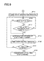
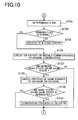
- Figs. 8 to 10 are flowcharts showing operation of the motor drive control device.
- step 1 the main CPU 31 initializes predetermined data (data stored in the main RAM 33, transmission data and the like).
- the main CPU 31 erases the data stored in the main RAM 33 at the time that the previous game is terminated. Concretely, the main CPU 31 erases parameters utilized in the previous game from the main RAM 33 and writes parameters utilized in the next game in the main RAM 33.
- the main CPU 31 determines whether or not 30 seconds are elapsed since the previous game is terminated (all reels 3L, 3C, 3R are stopped). In a case that 30 seconds are elapsed, the main CPU 31 executes the process in ST4, and on the other hand, if 30 seconds are not elapsed, the main CPU 31 executes the process in ST5.
- the main CPU 31 transmits "demonstration display command" to display demonstration image to a sub-control circuit 47.
- the main CPU 31 determines whether or not the "replay", which is one of the winning combinations, is won in the previous game. In a case that the "replay" is won, the main CPU 31 executes the process in ST6, and if the "replay" is not won, the main CPU 31 executes the process in ST7.
- the main CPU 31 automatically inserts a predetermined number of medals based on that the "replay" is won.
- the main CPU 31 determines whether or not medals are inserted by the player. Concretely, the main CPU 31 determines whether or not the switch signal is input from the medal sensor 22S or one of the BET switches 2a ⁇ 2c. And in a case that such switch signal is input to the main CPU 31, the main CPU 31 executes the process in ST8. On the other hand, in a case that such switch signal is not input to the main CPU 31, the main CPU 31 executes the process in ST3.
- the main CPU 31 determines whether or not the star lever 9 is operated by the player. Concretely, the main CPU 31 determines whether or not the switch signal is input from the start switch 6S. And in a case that the switch signal is input from the start switch 6S, the main CPU 31 executes the process in ST9.
- the main CPU 31 determines whether or not 4.1 seconds are elapsed since the previous game is started. And in a case that 4.1 seconds are elapsed, the main CPU 31 executes the process in ST11, and on the other hand, in a case that 4.1 seconds are not elapsed, the main CPU 31 executes the process in ST10.
- the main CPU 31 invalidates the input from the start switch 6S till 4.1 seconds are elapsed since the previous game is started.
- the main CPU 31 determines the predetermined symbol combination as the winning combination based on a lottery result.
- the main CPU 31 transmits the instruction command to the motor drive circuit 39 so that the reels 3 are rotated.
- the main CPU 31 extracts the random number which is utilized for various determinations.
- the main CPU 31 sets a predetermined time to the 1 game observation timer.
- the 1 game observation timer includes an automatic stop timer to which a predetermined time is set in order to automatically stop the reels 3 without stop operation by the player.
- the main CPU 31 determines whether or not the stop buttons 7L, 7C, 7R are operated by the player. Concretely, the main CPU 31 determines whether or not the input from the reel stop signal circuit 46 is "on”. And if such input from the reel stop signal circuit 46 is "on”, the main CPU 31 shifts the procedure to ST 18. On the other hand, if the input from the reel stop signal circuit 46 is "off", the main CPU 31 shifts the procedure to ST17.
- the main CPU 31 determines whether or not the value of the automatic stop timer is "0". And if such value is "0", the main CPU 31 conducts the process in ST18. On the other hand, if such value is not "0", the main CPU 31 conducts the process in ST17.
- the main CPU 31 determines the number of slide symbols.
- the main CPU 31 conducts the process to stop the reels 3. Detailed description thereof will be done hereinafter.
- the main CPU 31 determines whether or not all reels 3 are stopped. And if all reels 3 are stopped, the main CPU 31 conducts the process in ST21. On the other hand, if all reels 3 are not stopped, the main CPU 31 conducts the process in ST16.
- the main CPU 31 sets the command indicating that all reels 3 are stopped.
- the main CPU 31 conducts determination of a win (the winning combination).
- the determination of the win means that the winning flag is set in order to distinguish the winning combination based on the stop mode of the symbols along the panel display windows 5L, 5C, 5R.
- the main CPU 31 distinguish the winning combination based on the code numbers of the symbols stopped along the center pay line and the winning combination determination table (not shown).
- the main CPU 31 determines whether or not the winning flag is normal. And if the winning flag is normal, the main CPU 31 conducts the process in ST26. On the other hand, if the winning flag is not normal, the main CPU 31 conducts the process in ST 25.
- the main CPU 31 stores or pays out the medals corresponding to the winning combination.
- the main CPU 31 determines whether game condition is the "BB general game state” or the "RB game state”. And if game condition is the "BB general game state” or the "RB game state”, the main CPU 31 conducts the process in ST28. On the other hand, if game condition is not the "BB general game state” or the "RB game state", the main CPU 31 terminates procedure.
- the main CPU 31 checks the number of the BB game and the number of the RB game number. In this process, for example, the game number of the "BB general game state”, the occurrence number of the “RB game state” in the “BB general game state”, the game number in the "RB game state” and the winning number of times in the "RB game state” are checked.
- the main CPU 31 determines whether or not the "BB general game state” or the "RB game state” is terminated. And if games in the "BB general game state” or the "RB game state” are terminated, the main CPU 31 conducts the process in ST30. On the other hand, if games in the "BB general game state” or the "RB game state” are not terminated, the main CPU 31 conducts the process in ST2.
- the main CPU 31 clears the work area in the main RAM 33, the work area being used in the "BB general game state" or the "RB game state".
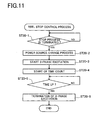
- Fig. 11 is a flowchart showing procedures in the reel stop control process in ST20.
- the main CPU 31 determines whether or not the stop process is terminated. And when the main CPU 31 determines that the stop process is not terminated, the main CPU 31 again conducts the process in ST20-1. And when the main CPU 31 determines that the stop process is terminated, procedure shifts to ST20-2.
- the main CPU 31 changes the power source A added to the stepping motor 49 which is rotating at the constant speed, to the power source B the voltage value of which is lower than that of the power source A.
- the main CPU 31 counts the time during which the excitation process by 2-phase excitation is executed.
- the main CPU 31 determines whether or not the time counted in ST20-4 exceeds a predetermined time. When the main CPU 31 determines that the counted time does not exceed the predetermined time, the main CPU 31 repeats this process in ST20-5. And when the main CPU 31 determines that the counted time exceeds the predetermined time, procedure shifts to ST20-6.
- the main CPU 31 terminates the excitation process by 2-phase excitation.
- the present invention is not limited to the above embodiment and various modifications may be done within the scope of the present invention.
- the stop control of the reels 3L, 3C, 3R (the stop control of the stepping motor 49) is conducted based on the signal output from the reel stop signal circuit 46 when any one of the stop buttons 7L, 7C, 7R is pressed
- the present invention is not limited.
- various triggers may be utilized.
- the main CPU 31 drops the voltage value added to the stepping motor rotating at the constant speed to the voltage value lower than such voltage value and executes the stop control of the stepping motor 49 by 2-phase excitation, thereby the reel 3 can be smoothly stopped and cost of the stepping motor 49 can be reduced.
- the motor stop control device can weak the holding torque even by utilizing the excitation process by 2-phase excitation. Accordingly, when the reel 3 is stopped, the process for changing to the lower power source and the excitation process by 2-phase excitation are executed, thereby the motor stop control device can smoothly stop the reel 3 without depending upon the stop by the detent torque.
Landscapes
- Physics & Mathematics (AREA)
- General Physics & Mathematics (AREA)
- Slot Machines And Peripheral Devices (AREA)
- Control Of Stepping Motors (AREA)
Applications Claiming Priority (2)
| Application Number | Priority Date | Filing Date | Title |
|---|---|---|---|
| JP2003324446A JP2005094910A (ja) | 2003-09-17 | 2003-09-17 | モータ停止制御装置 |
| JP2003324446 | 2003-09-17 |
Publications (2)
| Publication Number | Publication Date |
|---|---|
| EP1517279A2 true EP1517279A2 (de) | 2005-03-23 |
| EP1517279A3 EP1517279A3 (de) | 2005-08-03 |
Family
ID=34191300
Family Applications (1)
| Application Number | Title | Priority Date | Filing Date |
|---|---|---|---|
| EP04022041A Withdrawn EP1517279A3 (de) | 2003-09-17 | 2004-09-16 | Vorrichtung zum Anhalten eines Motors, die verwendbar in einem Spielautomaten ist, und Spielautomat mit einer solchen Vorrichtung |
Country Status (6)
| Country | Link |
|---|---|
| US (1) | US7199546B2 (de) |
| EP (1) | EP1517279A3 (de) |
| JP (1) | JP2005094910A (de) |
| CN (1) | CN100380414C (de) |
| AU (1) | AU2004212573A1 (de) |
| ZA (1) | ZA200407448B (de) |
Families Citing this family (8)
| Publication number | Priority date | Publication date | Assignee | Title |
|---|---|---|---|---|
| JP2007117257A (ja) * | 2005-10-26 | 2007-05-17 | Aruze Corp | 遊技機 |
| AU2008229938A1 (en) * | 2007-10-17 | 2009-05-07 | Aristocrat Technologies Australia Pty Limited | A gaming system and a method of gaming |
| US10363811B2 (en) * | 2013-06-13 | 2019-07-30 | Ford Global Technologies, Llc | Vehicle speed controlled active grille shutter system |
| JP6394099B2 (ja) * | 2014-06-18 | 2018-09-26 | オムロン株式会社 | 操作ユニット |
| JP2016171928A (ja) * | 2015-03-17 | 2016-09-29 | 株式会社大一商会 | 遊技機 |
| JP2016171930A (ja) * | 2015-03-17 | 2016-09-29 | 株式会社大一商会 | 遊技機 |
| KR101890201B1 (ko) * | 2016-09-12 | 2019-01-16 | 주식회사 엘코스 | 플렉서블 디스플레이를 이용한 릴 게임기 |
| JP7050266B2 (ja) * | 2018-03-23 | 2022-04-08 | 株式会社サンセイアールアンドディ | 遊技機 |
Family Cites Families (18)
| Publication number | Priority date | Publication date | Assignee | Title |
|---|---|---|---|---|
| GB1471866A (en) | 1974-06-27 | 1977-04-27 | Shaw A | Gaming machine |
| JPS58215997A (ja) | 1982-06-07 | 1983-12-15 | Diesel Kiki Co Ltd | ステツピングモ−タ駆動方法 |
| JPS59144398A (ja) * | 1983-02-02 | 1984-08-18 | West Electric Co Ltd | ステツピングモ−タの駆動制御装置 |
| JPS6083678U (ja) | 1983-11-14 | 1985-06-10 | 株式会社ユニバーサル | スロツトマシン |
| GB8403360D0 (en) * | 1984-02-08 | 1984-03-14 | Erba Farmitalia | Pharmaceutical compositions |
| US4697129A (en) | 1985-02-15 | 1987-09-29 | Teac Corporation | Stepping motor drive system and method capable of stopping the rotor in a required angular position |
| JPH0545337Y2 (de) * | 1985-03-25 | 1993-11-18 | ||
| JPH0532145Y2 (de) | 1985-08-23 | 1993-08-18 | ||
| US4858932A (en) * | 1988-04-21 | 1989-08-22 | Bally Manufacturing Corporation | Nonuniform probability reel stop mechanism for gaming machines |
| JP2693483B2 (ja) * | 1988-05-17 | 1997-12-24 | キヤノン株式会社 | シート搬送装置及びその装置を備えたフアクシミリ装置 |
| JPH02136097A (ja) | 1988-11-17 | 1990-05-24 | Canon Inc | 電源装置 |
| JPH02188196A (ja) | 1989-01-13 | 1990-07-24 | Copal Co Ltd | ステッピングモータの駆動制御方法 |
| CN1093841A (zh) * | 1993-04-14 | 1994-10-19 | 刘建强 | 脉冲调制式步进电机驱动电源 |
| US5627443A (en) | 1994-04-06 | 1997-05-06 | Unisia Jecs Corporation | Method of driving stepping motor |
| JPH0998599A (ja) | 1995-09-29 | 1997-04-08 | Nec Corp | ステップモータ用駆動装置 |
| JP3897840B2 (ja) | 1996-08-30 | 2007-03-28 | アルゼ株式会社 | リールユニット |
| US5938529A (en) * | 1997-03-17 | 1999-08-17 | Unislot, Inc. | Reel type slot machine having stepper motor monitoring system |
| US5988638A (en) * | 1997-06-13 | 1999-11-23 | Unislot, Inc. | Reel type slot machine utilizing random number generator for selecting game result |
-
2003
- 2003-09-17 JP JP2003324446A patent/JP2005094910A/ja active Pending
-
2004
- 2004-09-15 US US10/940,754 patent/US7199546B2/en not_active Expired - Lifetime
- 2004-09-16 EP EP04022041A patent/EP1517279A3/de not_active Withdrawn
- 2004-09-16 ZA ZA2004/07448A patent/ZA200407448B/en unknown
- 2004-09-17 CN CNB2004100797570A patent/CN100380414C/zh not_active Expired - Fee Related
- 2004-09-17 AU AU2004212573A patent/AU2004212573A1/en not_active Abandoned
Also Published As
| Publication number | Publication date |
|---|---|
| US7199546B2 (en) | 2007-04-03 |
| CN1608702A (zh) | 2005-04-27 |
| JP2005094910A (ja) | 2005-04-07 |
| AU2004212573A1 (en) | 2005-04-07 |
| CN100380414C (zh) | 2008-04-09 |
| EP1517279A3 (de) | 2005-08-03 |
| US20050083007A1 (en) | 2005-04-21 |
| ZA200407448B (en) | 2005-09-28 |
Similar Documents
| Publication | Publication Date | Title |
|---|---|---|
| EP1521221A2 (de) | Vorrichtung zum Anhalten eine Motors, die in einem Spielautomaten verwendbar ist, und Spielautomat, in dem sie verwendet wird | |
| US20020094862A1 (en) | Slot machine having a plurality of game lines | |
| EP1533764A2 (de) | Vorrichtung zur Steuerung des Anhaltens eines Motors für einen Spielautomaten und Spielautomaten mit einer solchen Vorrichtung | |
| EP1517279A2 (de) | Vorrichtung zum Anhalten eines Motors, die verwendbar in einem Spielautomaten ist, und Spielautomat mit einer solchen Vorrichtung | |
| US20070004495A1 (en) | Gaming machine and method | |
| JP4139728B2 (ja) | 遊技機及びプログラム及び記憶媒体 | |
| JP2002000795A (ja) | 遊技機 | |
| JP5283892B2 (ja) | 遊技機 | |
| JP2001070515A (ja) | 遊技機 | |
| JP2005245701A (ja) | 遊技機 | |
| US20070026931A1 (en) | Gaming machine | |
| JP2006204624A (ja) | 遊技機 | |
| EP1515286A2 (de) | Vorrichtung für Motorsteuerung, die verwendbar in einem Spielautomaten ist, und Spielautomat mit einer solchen Vorrichtung | |
| EP1752940A1 (de) | Spielautomat | |
| JP4139729B2 (ja) | 遊技機及びプログラム及び記憶媒体 | |
| JP2007117258A (ja) | 遊技機 | |
| JP4437412B2 (ja) | 遊技機 | |
| JP4292023B2 (ja) | 遊技機の制御装置 | |
| JP6300966B2 (ja) | 遊技機 | |
| JP6087408B2 (ja) | 遊技機 | |
| JP5818845B2 (ja) | 遊技機 | |
| JP2005124750A (ja) | 遊技機、プログラム及び記録媒体 | |
| JP2002306678A (ja) | 遊技機 | |
| JP2002360764A (ja) | 遊技機及びプログラム及び記憶媒体 | |
| JP2002210081A (ja) | 遊技機 |
Legal Events
| Date | Code | Title | Description |
|---|---|---|---|
| PUAI | Public reference made under article 153(3) epc to a published international application that has entered the european phase |
Free format text: ORIGINAL CODE: 0009012 |
|
| AK | Designated contracting states |
Kind code of ref document: A2 Designated state(s): AT BE BG CH CY CZ DE DK EE ES FI FR GB GR HU IE IT LI LU MC NL PL PT RO SE SI SK TR |
|
| AX | Request for extension of the european patent |
Extension state: AL HR LT LV MK |
|
| PUAL | Search report despatched |
Free format text: ORIGINAL CODE: 0009013 |
|
| AK | Designated contracting states |
Kind code of ref document: A3 Designated state(s): AT BE BG CH CY CZ DE DK EE ES FI FR GB GR HU IE IT LI LU MC NL PL PT RO SE SI SK TR |
|
| AX | Request for extension of the european patent |
Extension state: AL HR LT LV MK |
|
| 17P | Request for examination filed |
Effective date: 20060103 |
|
| AKX | Designation fees paid |
Designated state(s): AT BE BG CH CY CZ DE DK EE ES FI FR GB GR HU IE IT LI LU MC NL PL PT RO SE SI SK TR |
|
| 17Q | First examination report despatched |
Effective date: 20101020 |
|
| STAA | Information on the status of an ep patent application or granted ep patent |
Free format text: STATUS: THE APPLICATION IS DEEMED TO BE WITHDRAWN |
|
| 18D | Application deemed to be withdrawn |
Effective date: 20110301 |