EP1517130B1 - Messung der Permeabilität eines umlaufenden Bandes - Google Patents
Messung der Permeabilität eines umlaufenden Bandes Download PDFInfo
- Publication number
- EP1517130B1 EP1517130B1 EP04104197.1A EP04104197A EP1517130B1 EP 1517130 B1 EP1517130 B1 EP 1517130B1 EP 04104197 A EP04104197 A EP 04104197A EP 1517130 B1 EP1517130 B1 EP 1517130B1
- Authority
- EP
- European Patent Office
- Prior art keywords
- belt
- nozzle
- measuring head
- contact pressure
- measuring
- Prior art date
- Legal status (The legal status is an assumption and is not a legal conclusion. Google has not performed a legal analysis and makes no representation as to the accuracy of the status listed.)
- Expired - Lifetime
Links
- 230000035699 permeability Effects 0.000 title claims description 8
- 238000005259 measurement Methods 0.000 title description 15
- 238000000034 method Methods 0.000 claims description 16
- 239000012530 fluid Substances 0.000 claims description 14
- 238000005299 abrasion Methods 0.000 claims description 2
- 239000000463 material Substances 0.000 claims description 2
- 239000000523 sample Substances 0.000 description 3
- 231100000681 Certain safety factor Toxicity 0.000 description 1
- 229910010293 ceramic material Inorganic materials 0.000 description 1
- 238000010276 construction Methods 0.000 description 1
Images

Classifications
-
- G—PHYSICS
- G01—MEASURING; TESTING
- G01N—INVESTIGATING OR ANALYSING MATERIALS BY DETERMINING THEIR CHEMICAL OR PHYSICAL PROPERTIES
- G01N15/00—Investigating characteristics of particles; Investigating permeability, pore-volume or surface-area of porous materials
- G01N15/08—Investigating permeability, pore-volume, or surface area of porous materials
- G01N15/082—Investigating permeability by forcing a fluid through a sample
Definitions
- the invention relates to a method for measuring the permeability of a circulating belt, in particular a dewatering belt in a paper machine, with a nozzle, from which a measuring fluid flows onto the belt.
- Permeability measurements on circulating belts must usually be carried out with a high pressure of the measuring fluid, so that the flow of the measuring fluid can penetrate the belt. Therefore, it is necessary to press the nozzle correspondingly strong against the belt, since the volume flow of the measuring fluid generates a correspondingly high reaction force to the nozzle, and thus pushes the nozzle away from the belt. In particular, when pressure fluctuations in the flow of the measuring fluid occur, there is a risk that the nozzle is lifted from the force acting on them reaction force from the tape, resulting in a faulty permeability measurement can result.
- Such a device is eg in the US 4,880,499 described.
- the invention therefore has the object to improve a method of the type mentioned in that a lifting of the nozzle from the belt at pressure peaks due to pressure fluctuations in the measuring fluid is avoided.
- the invention achieves the stated object by the use of a device in which, according to the invention, the nozzle can be pressed against the circulating belt with a constant contact pressure. Consequently, pressure fluctuations in the measuring fluid due to the constant contact pressure of the nozzle against the circulating belt can no longer affect the measuring accuracy of the device. This is in a broader sense also a prerequisite for making several measurements comparable, in particular also with regard to different types of clothing and different systems.
- the required contact pressure increases with the increasing discharge pressure of the measuring fluid from the nozzle, with the belt speed and with the belt tension. Therefore, it is expedient if the contact pressure in dependence on the outlet pressure of the measuring fluid from the nozzle and / or from the belt speed and / or from the belt tension is adjustable. It makes sense for the contact pressure to be at least equal to the nozzle outlet pressure in order to be able to carry out a permeability measurement providing trouble-free and accurate measurement results.
- the nozzle is integrated in a measuring head.
- This measuring head ensures a defined surface, with which the tape is in contact during the measurement. It also ensures that the nozzle is always placed in the same way on the felt. So that the volume flow can penetrate the band best, it makes sense if the nozzle is positioned perpendicular to the tape during the measurement.
- Facilities for measuring the belt speed, the nozzle outlet speed and the nozzle outlet pressure can be connected to the measuring head.
- the measuring head can be pressed against the belt with a specific contact pressure and / or the nozzle can additionally be pressed against the belt within the measuring head independently of the contact pressure of the measuring head.
- the opening of the nozzle has a defined area.
- the nozzle is preferably designed such that possible leakage losses are minimized.
- the measuring head may have a contact surface which can be pressed on the strip. In this way, the defined area described above is ensured during the measurement.
- the measuring head is designed as a frame. This construction also limits the defined measuring area for the measurement.
- the frame can be provided with slide rails and / or rollers.
- the measuring head is made of an abrasion-resistant material, in particular of a ceramic material, this has a particularly long service life.
- the contact force required to produce the contact pressure can be provided with a certain safety factor.
- This safety factor for the contact pressure can be in an interval of 1 to 20.
- a particularly good contact pressure of the nozzle against the tape is achieved when the contact pressure of the measuring head against the tape in the range of 200 to 1,500 N / m 2 . Taking into account the lowest possible friction at the highest possible belt speed, good measuring results are achieved, in particular with a contact pressure in the range of 400 to 800 N / m 2 . In general, the contact pressure of the nozzle is >> than the contact pressure of the measuring head.
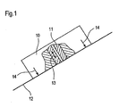
- the FIG. 1 shows a measuring head 10, in which a nozzle 11 with a preferred nozzle opening diameter of 1 mm and with a preferred Nozzle outer diameter of 10 mm is arranged.
- a circulating belt 12 which is a dewatering belt of a paper machine, passes through.
- a permeability measurement of the belt 12 is to be performed.
- a volume flow of a measuring fluid provided with a high pressure is pressed out of the nozzle 11 through the band 12. Due to the high nozzle outlet pressure of the measuring fluid, the high belt speed of the belt 12 and the high tension of the belt, the nozzle 11 must be pressed against the belt 12 with as high a contact pressure as possible.
- the nozzle 11 is pressed against the belt 12 with a contact pressure represented by the arrow 13.
- This contact pressure depends, among other things, on the nozzle shape and on the strip surface.
- the measuring head 10 is additionally pressed against the belt 12 by a contact pressure represented by the arrows 14.
- This contact pressure is preferably in a range of 200 to 1,500 N / m 2 . In this way, a maximum contact pressure of the nozzle 11 and the measuring head 10 can be ensured against the belt 12. Since the nozzle 11 should be arranged perpendicular to the belt 12 for an optimum measurement result, it is important that the measuring head 10 is strongly pressed against the belt 12. This ensures that the nozzle 11 is always placed vertically on the belt 12.
- the FIG. 2 shows a measuring head 20, in which a nozzle 11 is arranged.
- the measuring head 20 has a flat contact surface 21.
- the measuring head 20 is placed with the flat contact surface 21 on the belt 12.
- the flat contact surface 21 ensures that the nozzle 11 is always positioned perpendicular to the band 12 during the measuring process.
- the flat contact surface 21 forms a defined measuring surface for the measuring process.
- FIGS. 4 and 5 show a measuring head 30 which is provided with rollers 31 and the nozzle 11.
- the rollers 31 are interconnected by connecting elements 32.
- the rollers 31 and the connecting elements 32 thus form a frame 33.
- the frame 33 forms a defined measuring surface for the measuring process. It also ensures that the nozzle 11 is always pressed perpendicularly against the belt 12.
- the rollers 31 are placed on the belt 12. As a result, a low friction between the measuring head 30 and the belt 12 is ensured.
- the contact pressure of the measuring heads 10, 20 and 30 can be adjusted. To ensure error-free permeability measurement, it must be ensured that the contact pressure is at least equal to the nozzle outlet pressure.
Landscapes
- Chemical & Material Sciences (AREA)
- Dispersion Chemistry (AREA)
- Physics & Mathematics (AREA)
- Health & Medical Sciences (AREA)
- Life Sciences & Earth Sciences (AREA)
- Analytical Chemistry (AREA)
- Biochemistry (AREA)
- General Health & Medical Sciences (AREA)
- General Physics & Mathematics (AREA)
- Immunology (AREA)
- Pathology (AREA)
- Paper (AREA)
- Treatment Of Fiber Materials (AREA)
Description
- Die Erfindung betrifft ein Verfahren zur Messung der Permeabilität eines umlaufenden Bandes, insbesondere eines Entwässerungsbandes in einer Papiermaschine, mit einer Düse, aus der ein Messfluid auf das Band strömt.
- Permeabilitätsmessungen an umlaufenden Bändern müssen in der Regel mit einem hohen Druck des Messfluids durchgeführt werden, damit der Strom des Messfluids das Band durchdringen kann. Deshalb ist es erforderlich, die Düse entsprechend stark gegen das Band zu pressen, da der Volumenstrom des Messfluids eine entsprechend hohe Reaktionskraft auf die Düse erzeugt, und somit die Düse vom Band weg drückt. Insbesondere dann, wenn Druckschwankungen im Volumenstrom des Messfluids auftreten, besteht die Gefahr, dass die Düse von der auf sie wirkenden Reaktionskraft vom Band abgehoben wird, woraus eine fehlerhafte Permeabilitätsmessung resultieren kann.
- Eine derartige Vorrichtung wird z.B. in der
US 4,880,499 beschrieben. - Die Erfindung hat deshalb die Aufgabe ein Verfahren der eingangs genannten Art dahingehend zu verbessern, dass ein Abheben der Düse vom Band bei Druckspitzen infolge von Druckschwankungen im Messfluid vermieden wird.
- Die Erfindung löst die gestellte Aufgabe durch die Verwendung einer Vorrichtung, bei der erfindungsgemäß die Düse mit einem konstanten Anpressdruck auf das umlaufende Band anpressbar ist. Folglich können Druckschwankungen im Messfluid durch den stets konstanten Anpressdruck der Düse gegen das umlaufende Band die Messgenauigkeit der Vorrichtung nicht mehr beeinflussen. Dies ist im weiteren Sinne auch eine Voraussetzung dafür, dass mehrere Messungen miteinander vergleichbar werden, insbesondere auch im Hinblick auf verschiedene Bespannungen und verschiedene Anlagen.
- Der erforderliche Anpressdruck steigt mit dem zunehmenden Austrittsdruck des Messfluids aus der Düse, mit der Bandgeschwindigkeit und mit der Bandspannung. Deshalb ist es zweckmäßig, wenn der Anpressdruck in Abhängigkeit vom Austrittsdruck des Messfluids aus der Düse und/oder von der Bandgeschwindigkeit und/oder von der Bandspannung einstellbar ist. Sinnvollerweise entspricht der Anpressdruck mindestens dem Düsenaustrittsdruck, um eine störungsfreie und genaue Messergebnisse liefernde Permeabilitätsmessung durchführen zu können.
- In der Vorrichtung ist die Düse in einem Messkopf integriert. Dieser Messkopf gewährleistet eine definierte Fläche, mit der das Band während der Messung in Berührung ist. Er gewährleistet außerdem, dass die Düse immer in gleicher Weise auf den Filz aufgesetzt wird. Damit der Volumenstrom das Band am besten durchdringen kann, ist es sinnvoll, wenn die Düse während der Messung senkrecht zum Band positioniert ist. Mit dem Messkopf können Einrichtungen zur Messung der Bandgeschwindigkeit, der Düsenaustrittsgeschwindigkeit und des Düsenaustrittsdruckes verbunden sein.
- Um eine optimale Anpressung der Düse während der Messung gegen das Band sicherstellen zu können, kann der Messkopf mit einem bestimmten Anpressdruck gegen das Band angepresst werden und/oder die Düse innerhalb des Messkopfes unabhängig vom Anpressdruck des Messkopfes zusätzlich gegen das Band angepresst werden. Die Auftrittsöffnung der Düse weist dabei eine definierte Fläche auf. Die Düse ist bevorzugt derart gestaltet, dass mögliche Leckageverlust möglichst gering sind.
- In einer bestimmten Ausführungsform kann der Messkopf eine auf dem Band anpressbare Kontaktfläche aufweisen. Auf diese Weise wird die oben beschriebene definierte Fläche während der Messung sichergestellt.
- In einer alternativen Ausführungsform ist es jedoch auch möglich, dass der Messkopf als ein Rahmen ausgebildet ist. Auch diese Konstruktion grenzt für die Messung die definierte Messfläche ab.
- Um während der Messung die Reibungsverhältnisse zwischen dem Messkopf und dem umlaufenden Band möglichst gering zu halten, kann der Rahmen mit Gleitschienen und/oder Rollen versehen sein.
- Wenn der Messkopf aus einem abriebfesten Material, insbesondere aus einem Keramikwerkstoff, gefertigt ist, weist dieser besonders hohe Standzeiten auf.
- Abhängig von der Größe der Düse kann die zur Erzeugung des Anpressdruckes erforderliche Anpresskraft mit einem bestimmten Sicherheitsfaktor versehen werden. Dieser Sicherheitsfaktor für die Anpresskraft kann in einem Intervall von 1 bis 20 liegen.
- Eine besonders gute Anpressung der Düse gegen das Band wird erzielt, wenn der Anpressdruck des Messkopfes gegen das Band im Bereich von 200 bis 1.500 N/m2 liegt. Berücksichtigt man eine möglichst geringe Reibung bei einer möglichst hohen Bandgeschwindigkeit, so werden insbesondere bei einem Anpressdruck im Bereich von 400 bis 800 N/m2 gute Messergebnisse erzielt. Im allgemeinen ist der Anpressdruck der Düse >> als der Anpressdruck des Messkopfes.
- Nachfolgend wird ein Ausführungsbeispiel der Verwendeten Vorrichtung anhand der beiliegenden Zeichnungen näher erläutert.
- Im Einzelnen zeigen:
- Figur 1
- eine Seitenansicht mit einem teilweisen Schnitt auf einen Messkopf mit Düse;
- Figur 2
- eine Draufsicht auf eine erste Ausführungsform eines Messkopfes;
- Figur 3
- eine Seitenansicht auf den Messkopf aus
Figur 1 ; - Figur 4
- eine Draufsicht auf eine weitere Ausführungsform eines Messkopfes;
- Figur 5
- eine Seitenansicht auf den Messkopf aus
Figur 4 . - Die
Figur 1 zeigt einen Messkopf 10, in dem eine Düse 11 mit einem vorzugsweisen Düsenöffnungsdurchmesser von 1 mm und mit einem vorzugsweisen Düsenaußendurchmesser von 10 mm angeordnet ist. Unter dem Messkopf 10 läuft ein umlaufendes Band 12, das ein Entwässerungsband einer Papiermaschine ist, durch. Mit dem Messkopf 10 und der Düse 11 soll eine Permeabilitätsmessung des Bandes 12 durchgeführt werden. Zu diesem Zweck wird aus der Düse 11 ein mit einem hohen Druck versehener Volumenstrom eines Messfluids durch das Band 12 gepresst. Aufgrund des hohen Düsenaustrittsdruckes des Messfluids, der hohen Bandgeschwindigkeit des Bandes 12 und der hohen Spannung des Bandes muss die Düse 11 mit einem möglichst hohen Anpressdruck gegen das Band 12 gedrückt werden. Um einen maximalen Anpressdruck der Düse 11 gegen das Band 12 sicherzustellen, wird die Düse 11 mit einem durch den Pfeil 13 dargestellten Anpressdruck gegen das Band 12 gedrückt. Dieser Anpressdruck ist unter anderem abhängig von der Düsenform und von der Bandoberfläche. Unabhängig vom Anpressdruck 13 der Düse 11 wird der Messkopf 10 zusätzlich durch einen mit den Pfeilen 14 dargestellten Anpressdruck gegen das Band 12 gedrückt. Dieser Anpressdruck liegt vorzugsweise in einem Bereich von 200 bis 1.500 N/m2. Auf diese Weise kann ein maximaler Anpressdruck der Düse 11 und des Messkopfes 10 gegen das Band 12 gewährleistet werden. Da die Düse 11 für ein optimales Messergebnis senkrecht auf dem Band 12 angeordnet werden sollte, ist es wichtig, dass der Messkopf 10 stark gegen das Band 12 gedrückt wird. Somit ist sichergestellt, dass die Düse 11 immer senkrecht auf das Band 12 aufgesetzt wird. - Die
Figur 2 zeigt einen Messkopf 20, in dem eine Düse 11 angeordnet ist. Der Messkopf 20 weist eine ebene Kontaktfläche 21 auf. Während des Messvorganges wird der Messkopf 20 mit der ebenen Kontaktfläche 21 auf das Band 12 aufgesetzt. Die ebene Kontaktfläche 21 stellt sicher, dass während des Messvorganges die Düse 11 immer senkrecht zum Band 12 positioniert ist. Außerdem bildet die ebene Kontaktfläche 21 eine definierte Messfläche für den Messvorgang. - Die
Figuren 4 und 5 zeigen einen Messkopf 30, der mit Rollen 31 und der Düse 11 versehen ist. Die Rollen 31 sind durch Verbindungselemente 32 miteinander verbunden. Die Rollen 31 und die Verbindungselemente 32 bilden somit einen Rahmen 33. Der Rahmen 33 bildet für den Messvorgang eine definierte Messfläche. Er stellt außerdem sicher, dass die Düse 11 immer senkrecht gegen das Band 12 gepresst wird. Während des Messvorganges sind die Rollen 31 auf das Band 12 aufgesetzt. Dadurch wird eine geringe Reibung zwischen dem Messkopf 30 und dem Band 12 sichergestellt. Abhängig vom Düsenaustrittsdruck des Messfluids aus der Düse 11, von der Geschwindigkeit des Bandes 12 und von der Spannung des Bandes 12 kann der Anpressdruck der Messköpfe 10, 20 und 30 eingestellt werden. Um eine fehlerfreie Permeabilitätsmessung zu gewährleisten, ist darauf zu achten, dass der Anpressdruck mindestens dem Düsenaustrittsdruck entspricht. -
- 10
- Messkopf
- 11
- Düse
- 12
- Band
- 13
- Pfeil
- 14
- Pfeil
- 20
- Messkopf
- 21
- Kontaktfläche
- 30
- Messkopf
- 31
- Rolle
- 32
- Verbindungselement
- 33
- Rahmen
Claims (9)
- Verfahren zur Messung der Permeabilität eines umlaufendes Bandes (12), insbesondere eines Entwässerungsbandes in einer Papiermaschine, mit einer Düse (11), aus der ein Messfluid auf das Band (12) strömt, wobei die Düse (11) mit einem konstanten Anpressdruck (13) auf das umlaufende Band (12) angepresst wird
dadurch gekennzeichnet,
dass die Düse (11) in einem Messkopf (10, 20, 30) integriert ist, der mit einem bestimmten Anpressdruck (14) gegen das Band (12) anpressbar ist und/oder die Düse (11) innerhalb des Messkopfes (10, 20, 30) unabhängig vom Anpressdruck (14) des Messkopfes (10, 20, 30) zusätzlich gegen das Band (12) angepresst wird. - Verfahren nach Anspruch 1,
dadurch gekennzeichnet,
dass der Anpressdruck (13) in Abhängigkeit vom Austrittsdruck des Messfluids aus der Düse (11) und/oder von der Bandgeschwindigkeit und/oder von der Bandspannung einstellbar ist. - Verfahren nach Anspruch 2,
dadurch gekennzeichnet,
dass der Anpressdruck (13) mindestens dem Düsenaustrittsdruck entspricht. - Verfahren nach Anspruch 1,
dadurch gekennzeichnet,
dass der Messkopf (10, 20, 30) eine auf dem Band (12) anpressbare Kontaktfläche (21) aufweist. - Verfahren nach Anspruch 1,
dadurch gekennzeichnet,
dass der Messkopf (10, 20, 30) als ein Rahmen (33) ausgebildet ist. - Verfahren nach Anspruch 5,
dadurch gekennzeichnet,
dass der Rahmen (33) mit Gleitschuhen und/oder Rollen (31) versehen ist. - Verfahren nach einem der Ansprüche 1 oder 4 bis 6,
dadurch gekennzeichnet,
dass der Messkopf (10, 20, 30) aus einem abriebfesten Material gefertigt ist. - Verfahren nach einem der Ansprüche 1 bis 7,
dadurch gekennzeichnet,
dass die Anpresskraft (13) zur Erzeugung des Anpressdruckes einen Sicherheitsfaktor von 1 bis 20 aufweist. - Verfahren nach einem der Ansprüche 1 bis 8,
dadurch gekennzeichnet,
dass der Anpressdruck (14) des Messkopfes (10) gegen das Band (12) im Bereich von 200 bis 1.500 N/m2 liegt.
Applications Claiming Priority (2)
| Application Number | Priority Date | Filing Date | Title |
|---|---|---|---|
| DE10343417A DE10343417A1 (de) | 2003-09-19 | 2003-09-19 | Vorrichtung zur Messung der Permeabilität eines umlaufenden Bandes |
| DE10343417 | 2003-09-19 |
Publications (2)
| Publication Number | Publication Date |
|---|---|
| EP1517130A1 EP1517130A1 (de) | 2005-03-23 |
| EP1517130B1 true EP1517130B1 (de) | 2015-08-19 |
Family
ID=34177836
Family Applications (1)
| Application Number | Title | Priority Date | Filing Date |
|---|---|---|---|
| EP04104197.1A Expired - Lifetime EP1517130B1 (de) | 2003-09-19 | 2004-09-02 | Messung der Permeabilität eines umlaufenden Bandes |
Country Status (3)
| Country | Link |
|---|---|
| US (1) | US7249491B2 (de) |
| EP (1) | EP1517130B1 (de) |
| DE (1) | DE10343417A1 (de) |
Families Citing this family (1)
| Publication number | Priority date | Publication date | Assignee | Title |
|---|---|---|---|---|
| AT518417B1 (de) * | 2016-04-25 | 2017-10-15 | Klaus Ing Bartelmuss | Verfahren und Vorrichtung zur Messung der Feuchtigkeit des auf einem Siebband befindlichen Pulpematerials |
Family Cites Families (7)
| Publication number | Priority date | Publication date | Assignee | Title |
|---|---|---|---|---|
| US3762211A (en) * | 1972-01-28 | 1973-10-02 | O Poulsen | Method and apparatus for continuously measuring the porosity of a moving wet porous continuous sheet |
| CA1292891C (en) * | 1986-05-20 | 1991-12-10 | Ivan I. Pikulik | Method and apparatus for measurement of the permeability to water |
| US4991425A (en) * | 1990-02-20 | 1991-02-12 | Appleton Mills | Portable gauge for measuring air flow in a papermaking machine |
| US5725737A (en) * | 1996-09-18 | 1998-03-10 | Pulp And Paper Research Institute Of Canada | Apparatus for the detection of holes and plugged spots |
| SE512011C3 (sv) * | 1998-04-23 | 2000-01-31 | Lorentzen & Wettre Ab | Foerfarande och apparat foer maetning av permeabiliteiten foer vatten hos genomtraenglia skikt |
| DE10343913A1 (de) * | 2003-09-19 | 2005-06-09 | Voith Paper Patent Gmbh | Vorrichtung und Verfahren zur Bestimmung der Permeabilität eines umlaufenden Bandes |
| DE10343516A1 (de) * | 2003-09-19 | 2005-05-04 | Voith Paper Patent Gmbh | Verfahren und Vorrichtung zur Bestimmung wenigstens einer Eigenschaft einer bewegten Bespannung |
-
2003
- 2003-09-19 DE DE10343417A patent/DE10343417A1/de not_active Withdrawn
-
2004
- 2004-09-02 EP EP04104197.1A patent/EP1517130B1/de not_active Expired - Lifetime
- 2004-09-16 US US10/942,385 patent/US7249491B2/en not_active Expired - Fee Related
Also Published As
| Publication number | Publication date |
|---|---|
| US7249491B2 (en) | 2007-07-31 |
| EP1517130A1 (de) | 2005-03-23 |
| US20050092069A1 (en) | 2005-05-05 |
| DE10343417A1 (de) | 2005-04-21 |
Similar Documents
| Publication | Publication Date | Title |
|---|---|---|
| DE2448794C2 (de) | Doppelbandpresse | |
| EP0682728B1 (de) | Dosiersystem für vorrichtung zum beschichten von materialbahnen, insbesondere papier- oder kartonbahnen | |
| DE3012732A1 (de) | Hydrostatisches stuetzelement, insbesondere fuer eine durchbiegungseinstellwalze | |
| DE60308970T2 (de) | Band für eine Papiermaschine | |
| DE3020669A1 (de) | Verfahren zur steuerung der liniendruckverteilung in einer walzeinrichtung sowie entsprechende walzeinrichtung | |
| DE2827495C2 (de) | ||
| DE2343427A1 (de) | Kontinuierlich arbeitende press- und kalibriervorrichtung zur herstellung von spanplatten | |
| DE2357388C2 (de) | Vorrichtung zur Messung und/oder Überwachung der Planlage eines Flächengebildes | |
| DE2555669A1 (de) | Vorrichtung zum abstreifen ueberschuessiger streichmasse | |
| DE3241939C2 (de) | Ablaßventil für ein Blutdruckmeßgerät | |
| DE1241642B (de) | Vorrichtung zum Messen der Spannung in einer sich bewegenden Bahn | |
| DE3007452A1 (de) | Verfahren zur steuerung oder regelung des auf eine materialbahn ausgeuebten druckes im walzenspalt eines walzwerkes, insbesondere eines kalanders, und walzwerk mit einer vorrichtung zur durchfuehrung des verfahrens | |
| CH649942A5 (de) | Querperforiermesser. | |
| DE19725726C2 (de) | Verfahren zur Planheitsmessung von Bändern, insbesondere Metallbändern | |
| DE3036794A1 (de) | Foerdervorrichtung fuer band- und folienmaterial fuer bandbearbeitungsmaschinen | |
| DE69203860T2 (de) | Pressanordnung für eine fortlaufende bahn. | |
| EP0629494B1 (de) | Kontinuierlich arbeitende Materialpresse | |
| DE2857504C2 (de) | Vorrichtung zur Regelung der Dicke von thermoplastischen Folien | |
| EP0538771A1 (de) | Verfahren zur Diagnose des Verschleisses von bewegten Maschinenteilen | |
| DE3605613C2 (de) | ||
| EP1517130A1 (de) | Vorrichtung zur Messung der Permeabilität eines umlaufenden Bandes | |
| EP1260633A2 (de) | Maschine zur Herstellung einer Faserstoffbahn aus einer Faserstoffsuspension sowie Verfahren und System zur Überwachung eines Entwässerungselements | |
| DE2653875C3 (de) | Vorrichtung für die Ultrafiltration | |
| DE2812946C3 (de) | Vorrichtung zum Beschichten einer endlosen Bahn | |
| DE69217073T2 (de) | Entwasserungseinheit mit automatischer schlitzdüse |
Legal Events
| Date | Code | Title | Description |
|---|---|---|---|
| PUAI | Public reference made under article 153(3) epc to a published international application that has entered the european phase |
Free format text: ORIGINAL CODE: 0009012 |
|
| AK | Designated contracting states |
Kind code of ref document: A1 Designated state(s): AT BE BG CH CY CZ DE DK EE ES FI FR GB GR HU IE IT LI LU MC NL PL PT RO SE SI SK TR |
|
| AX | Request for extension of the european patent |
Extension state: AL HR LT LV MK |
|
| 17P | Request for examination filed |
Effective date: 20050923 |
|
| AKX | Designation fees paid |
Designated state(s): AT BE BG CH CY CZ DE DK EE ES FI FR GB GR HU IE IT LI LU MC NL PL PT RO SE SI SK TR |
|
| RAP1 | Party data changed (applicant data changed or rights of an application transferred) |
Owner name: VOITH PATENT GMBH |
|
| 17Q | First examination report despatched |
Effective date: 20100414 |
|
| GRAP | Despatch of communication of intention to grant a patent |
Free format text: ORIGINAL CODE: EPIDOSNIGR1 |
|
| INTG | Intention to grant announced |
Effective date: 20150424 |
|
| GRAS | Grant fee paid |
Free format text: ORIGINAL CODE: EPIDOSNIGR3 |
|
| GRAA | (expected) grant |
Free format text: ORIGINAL CODE: 0009210 |
|
| AK | Designated contracting states |
Kind code of ref document: B1 Designated state(s): AT BE BG CH CY CZ DE DK EE ES FI FR GB GR HU IE IT LI LU MC NL PL PT RO SE SI SK TR |
|
| REG | Reference to a national code |
Ref country code: GB Ref legal event code: FG4D Free format text: NOT ENGLISH |
|
| REG | Reference to a national code |
Ref country code: CH Ref legal event code: EP |
|
| REG | Reference to a national code |
Ref country code: IE Ref legal event code: FG4D Free format text: LANGUAGE OF EP DOCUMENT: GERMAN |
|
| REG | Reference to a national code |
Ref country code: AT Ref legal event code: REF Ref document number: 744154 Country of ref document: AT Kind code of ref document: T Effective date: 20150915 |
|
| REG | Reference to a national code |
Ref country code: DE Ref legal event code: R096 Ref document number: 502004014996 Country of ref document: DE |
|
| REG | Reference to a national code |
Ref country code: NL Ref legal event code: MP Effective date: 20150819 |
|
| PG25 | Lapsed in a contracting state [announced via postgrant information from national office to epo] |
Ref country code: GR Free format text: LAPSE BECAUSE OF FAILURE TO SUBMIT A TRANSLATION OF THE DESCRIPTION OR TO PAY THE FEE WITHIN THE PRESCRIBED TIME-LIMIT Effective date: 20151120 |
|
| PG25 | Lapsed in a contracting state [announced via postgrant information from national office to epo] |
Ref country code: ES Free format text: LAPSE BECAUSE OF FAILURE TO SUBMIT A TRANSLATION OF THE DESCRIPTION OR TO PAY THE FEE WITHIN THE PRESCRIBED TIME-LIMIT Effective date: 20150819 Ref country code: PL Free format text: LAPSE BECAUSE OF FAILURE TO SUBMIT A TRANSLATION OF THE DESCRIPTION OR TO PAY THE FEE WITHIN THE PRESCRIBED TIME-LIMIT Effective date: 20150819 Ref country code: SE Free format text: LAPSE BECAUSE OF FAILURE TO SUBMIT A TRANSLATION OF THE DESCRIPTION OR TO PAY THE FEE WITHIN THE PRESCRIBED TIME-LIMIT Effective date: 20150819 Ref country code: PT Free format text: LAPSE BECAUSE OF FAILURE TO SUBMIT A TRANSLATION OF THE DESCRIPTION OR TO PAY THE FEE WITHIN THE PRESCRIBED TIME-LIMIT Effective date: 20151221 |
|
| PG25 | Lapsed in a contracting state [announced via postgrant information from national office to epo] |
Ref country code: NL Free format text: LAPSE BECAUSE OF FAILURE TO SUBMIT A TRANSLATION OF THE DESCRIPTION OR TO PAY THE FEE WITHIN THE PRESCRIBED TIME-LIMIT Effective date: 20150819 |
|
| PG25 | Lapsed in a contracting state [announced via postgrant information from national office to epo] |
Ref country code: SK Free format text: LAPSE BECAUSE OF FAILURE TO SUBMIT A TRANSLATION OF THE DESCRIPTION OR TO PAY THE FEE WITHIN THE PRESCRIBED TIME-LIMIT Effective date: 20150819 Ref country code: CZ Free format text: LAPSE BECAUSE OF FAILURE TO SUBMIT A TRANSLATION OF THE DESCRIPTION OR TO PAY THE FEE WITHIN THE PRESCRIBED TIME-LIMIT Effective date: 20150819 Ref country code: DK Free format text: LAPSE BECAUSE OF FAILURE TO SUBMIT A TRANSLATION OF THE DESCRIPTION OR TO PAY THE FEE WITHIN THE PRESCRIBED TIME-LIMIT Effective date: 20150819 Ref country code: EE Free format text: LAPSE BECAUSE OF FAILURE TO SUBMIT A TRANSLATION OF THE DESCRIPTION OR TO PAY THE FEE WITHIN THE PRESCRIBED TIME-LIMIT Effective date: 20150819 Ref country code: IT Free format text: LAPSE BECAUSE OF FAILURE TO SUBMIT A TRANSLATION OF THE DESCRIPTION OR TO PAY THE FEE WITHIN THE PRESCRIBED TIME-LIMIT Effective date: 20150819 |
|
| REG | Reference to a national code |
Ref country code: CH Ref legal event code: PL |
|
| REG | Reference to a national code |
Ref country code: DE Ref legal event code: R097 Ref document number: 502004014996 Country of ref document: DE |
|
| PG25 | Lapsed in a contracting state [announced via postgrant information from national office to epo] |
Ref country code: RO Free format text: LAPSE BECAUSE OF FAILURE TO SUBMIT A TRANSLATION OF THE DESCRIPTION OR TO PAY THE FEE WITHIN THE PRESCRIBED TIME-LIMIT Effective date: 20150819 Ref country code: MC Free format text: LAPSE BECAUSE OF FAILURE TO SUBMIT A TRANSLATION OF THE DESCRIPTION OR TO PAY THE FEE WITHIN THE PRESCRIBED TIME-LIMIT Effective date: 20150819 |
|
| PLBE | No opposition filed within time limit |
Free format text: ORIGINAL CODE: 0009261 |
|
| STAA | Information on the status of an ep patent application or granted ep patent |
Free format text: STATUS: NO OPPOSITION FILED WITHIN TIME LIMIT |
|
| REG | Reference to a national code |
Ref country code: IE Ref legal event code: MM4A |
|
| REG | Reference to a national code |
Ref country code: FR Ref legal event code: ST Effective date: 20160531 |
|
| 26N | No opposition filed |
Effective date: 20160520 |
|
| GBPC | Gb: european patent ceased through non-payment of renewal fee |
Effective date: 20151119 |
|
| PG25 | Lapsed in a contracting state [announced via postgrant information from national office to epo] |
Ref country code: CH Free format text: LAPSE BECAUSE OF NON-PAYMENT OF DUE FEES Effective date: 20150930 Ref country code: IE Free format text: LAPSE BECAUSE OF NON-PAYMENT OF DUE FEES Effective date: 20150902 Ref country code: LI Free format text: LAPSE BECAUSE OF NON-PAYMENT OF DUE FEES Effective date: 20150930 |
|
| PG25 | Lapsed in a contracting state [announced via postgrant information from national office to epo] |
Ref country code: SI Free format text: LAPSE BECAUSE OF FAILURE TO SUBMIT A TRANSLATION OF THE DESCRIPTION OR TO PAY THE FEE WITHIN THE PRESCRIBED TIME-LIMIT Effective date: 20150819 Ref country code: FR Free format text: LAPSE BECAUSE OF NON-PAYMENT OF DUE FEES Effective date: 20151019 |
|
| PG25 | Lapsed in a contracting state [announced via postgrant information from national office to epo] |
Ref country code: GB Free format text: LAPSE BECAUSE OF NON-PAYMENT OF DUE FEES Effective date: 20151119 |
|
| PG25 | Lapsed in a contracting state [announced via postgrant information from national office to epo] |
Ref country code: HU Free format text: LAPSE BECAUSE OF FAILURE TO SUBMIT A TRANSLATION OF THE DESCRIPTION OR TO PAY THE FEE WITHIN THE PRESCRIBED TIME-LIMIT; INVALID AB INITIO Effective date: 20040902 Ref country code: BG Free format text: LAPSE BECAUSE OF FAILURE TO SUBMIT A TRANSLATION OF THE DESCRIPTION OR TO PAY THE FEE WITHIN THE PRESCRIBED TIME-LIMIT Effective date: 20150819 |
|
| PG25 | Lapsed in a contracting state [announced via postgrant information from national office to epo] |
Ref country code: CY Free format text: LAPSE BECAUSE OF FAILURE TO SUBMIT A TRANSLATION OF THE DESCRIPTION OR TO PAY THE FEE WITHIN THE PRESCRIBED TIME-LIMIT Effective date: 20150819 |
|
| PG25 | Lapsed in a contracting state [announced via postgrant information from national office to epo] |
Ref country code: BE Free format text: LAPSE BECAUSE OF NON-PAYMENT OF DUE FEES Effective date: 20150930 |
|
| PG25 | Lapsed in a contracting state [announced via postgrant information from national office to epo] |
Ref country code: TR Free format text: LAPSE BECAUSE OF FAILURE TO SUBMIT A TRANSLATION OF THE DESCRIPTION OR TO PAY THE FEE WITHIN THE PRESCRIBED TIME-LIMIT Effective date: 20150819 |
|
| PG25 | Lapsed in a contracting state [announced via postgrant information from national office to epo] |
Ref country code: LU Free format text: LAPSE BECAUSE OF NON-PAYMENT OF DUE FEES Effective date: 20150902 |
|
| PGFP | Annual fee paid to national office [announced via postgrant information from national office to epo] |
Ref country code: FI Payment date: 20230920 Year of fee payment: 20 Ref country code: AT Payment date: 20230921 Year of fee payment: 20 |
|
| PGFP | Annual fee paid to national office [announced via postgrant information from national office to epo] |
Ref country code: DE Payment date: 20230920 Year of fee payment: 20 |
|
| REG | Reference to a national code |
Ref country code: DE Ref legal event code: R071 Ref document number: 502004014996 Country of ref document: DE |
|
| REG | Reference to a national code |
Ref country code: AT Ref legal event code: MK07 Ref document number: 744154 Country of ref document: AT Kind code of ref document: T Effective date: 20240902 |