EP1516976B1 - Multilayered floor covering element with grooves for connecting profiles - Google Patents
Multilayered floor covering element with grooves for connecting profiles Download PDFInfo
- Publication number
- EP1516976B1 EP1516976B1 EP04021868A EP04021868A EP1516976B1 EP 1516976 B1 EP1516976 B1 EP 1516976B1 EP 04021868 A EP04021868 A EP 04021868A EP 04021868 A EP04021868 A EP 04021868A EP 1516976 B1 EP1516976 B1 EP 1516976B1
- Authority
- EP
- European Patent Office
- Prior art keywords
- grooves
- resistant
- material layer
- floor
- elements
- Prior art date
- Legal status (The legal status is an assumption and is not a legal conclusion. Google has not performed a legal analysis and makes no representation as to the accuracy of the status listed.)
- Expired - Lifetime
Links
- 239000003562 lightweight material Substances 0.000 claims description 34
- 238000005299 abrasion Methods 0.000 claims description 10
- 230000001070 adhesive effect Effects 0.000 claims description 7
- 239000000853 adhesive Substances 0.000 claims description 6
- 239000004743 Polypropylene Substances 0.000 claims description 3
- -1 polypropylene Polymers 0.000 claims description 3
- 229920001155 polypropylene Polymers 0.000 claims description 3
- 239000010410 layer Substances 0.000 description 53
- 239000004575 stone Substances 0.000 description 10
- 238000007789 sealing Methods 0.000 description 8
- 239000004918 carbon fiber reinforced polymer Substances 0.000 description 6
- 239000004033 plastic Substances 0.000 description 6
- 230000002787 reinforcement Effects 0.000 description 6
- 239000004744 fabric Substances 0.000 description 5
- 239000000463 material Substances 0.000 description 5
- 238000010438 heat treatment Methods 0.000 description 4
- 239000002184 metal Substances 0.000 description 4
- 239000004570 mortar (masonry) Substances 0.000 description 4
- 230000003014 reinforcing effect Effects 0.000 description 4
- 238000004026 adhesive bonding Methods 0.000 description 3
- 238000010276 construction Methods 0.000 description 3
- 230000008719 thickening Effects 0.000 description 3
- 239000002023 wood Substances 0.000 description 3
- 229920006328 Styrofoam Polymers 0.000 description 2
- 239000000919 ceramic Substances 0.000 description 2
- 230000005494 condensation Effects 0.000 description 2
- 238000009833 condensation Methods 0.000 description 2
- 239000006260 foam Substances 0.000 description 2
- 239000011888 foil Substances 0.000 description 2
- 239000011521 glass Substances 0.000 description 2
- 239000011229 interlayer Substances 0.000 description 2
- 239000000123 paper Substances 0.000 description 2
- 239000008261 styrofoam Substances 0.000 description 2
- 239000000758 substrate Substances 0.000 description 2
- XLYOFNOQVPJJNP-UHFFFAOYSA-N water Substances O XLYOFNOQVPJJNP-UHFFFAOYSA-N 0.000 description 2
- 239000011324 bead Substances 0.000 description 1
- 230000005540 biological transmission Effects 0.000 description 1
- 239000012876 carrier material Substances 0.000 description 1
- 239000011093 chipboard Substances 0.000 description 1
- 239000002131 composite material Substances 0.000 description 1
- 150000001875 compounds Chemical class 0.000 description 1
- 239000004567 concrete Substances 0.000 description 1
- 230000001419 dependent effect Effects 0.000 description 1
- 238000006073 displacement reaction Methods 0.000 description 1
- 230000000694 effects Effects 0.000 description 1
- 239000013013 elastic material Substances 0.000 description 1
- 239000003822 epoxy resin Substances 0.000 description 1
- 238000009408 flooring Methods 0.000 description 1
- 239000003365 glass fiber Substances 0.000 description 1
- 238000009434 installation Methods 0.000 description 1
- 238000009413 insulation Methods 0.000 description 1
- 210000001503 joint Anatomy 0.000 description 1
- 238000000034 method Methods 0.000 description 1
- 230000000149 penetrating effect Effects 0.000 description 1
- 229920000647 polyepoxide Polymers 0.000 description 1
- 230000003763 resistance to breakage Effects 0.000 description 1
- 239000004753 textile Substances 0.000 description 1
Images

Classifications
-
- E—FIXED CONSTRUCTIONS
- E04—BUILDING
- E04F—FINISHING WORK ON BUILDINGS, e.g. STAIRS, FLOORS
- E04F15/00—Flooring
- E04F15/02—Flooring or floor layers composed of a number of similar elements
- E04F15/08—Flooring or floor layers composed of a number of similar elements only of stone or stone-like material, e.g. ceramics, concrete; of glass or with a top layer of stone or stone-like material, e.g. ceramics, concrete or glass
-
- E—FIXED CONSTRUCTIONS
- E04—BUILDING
- E04F—FINISHING WORK ON BUILDINGS, e.g. STAIRS, FLOORS
- E04F15/00—Flooring
- E04F15/02—Flooring or floor layers composed of a number of similar elements
-
- E—FIXED CONSTRUCTIONS
- E04—BUILDING
- E04F—FINISHING WORK ON BUILDINGS, e.g. STAIRS, FLOORS
- E04F15/00—Flooring
- E04F15/02—Flooring or floor layers composed of a number of similar elements
- E04F15/02005—Construction of joints, e.g. dividing strips
- E04F15/02016—Construction of joints, e.g. dividing strips with sealing elements between flooring elements
-
- E—FIXED CONSTRUCTIONS
- E04—BUILDING
- E04F—FINISHING WORK ON BUILDINGS, e.g. STAIRS, FLOORS
- E04F15/00—Flooring
- E04F15/18—Separately-laid insulating layers; Other additional insulating measures; Floating floors
- E04F15/185—Underlayers in the form of studded or ribbed plates
-
- E—FIXED CONSTRUCTIONS
- E04—BUILDING
- E04F—FINISHING WORK ON BUILDINGS, e.g. STAIRS, FLOORS
- E04F2201/00—Joining sheets or plates or panels
- E04F2201/05—Separate connectors or inserts, e.g. pegs, pins, keys or strips
- E04F2201/0511—Strips or bars, e.g. nailing strips
-
- E—FIXED CONSTRUCTIONS
- E04—BUILDING
- E04F—FINISHING WORK ON BUILDINGS, e.g. STAIRS, FLOORS
- E04F2201/00—Joining sheets or plates or panels
- E04F2201/05—Separate connectors or inserts, e.g. pegs, pins, keys or strips
- E04F2201/0517—U- or C-shaped brackets and clamps
Definitions
- the invention relates to a laminar, multi-layer element for floors, with a thin pressure and abrasion resistant cover plate, which forms the top of the multilayer element, and in which at the bottom of the thin pressure and abrasion resistant cover plate attached to this by an adhesive bond, pressure-resistant carrier element is located, wherein in vertical edge surfaces grooves are arranged and in the grooves for connecting adjacent laid multilayer elements connecting strips are attached.
- the invention is particularly intended for removable and thus reusable floors.
- removable and reusable floors which are needed for example for exhibitions, it has not been possible to make flat and high quality floor surfaces with high load capacity, especially using thin and thus lightweight natural stone slabs.
- the floor element is also suitable for laying on underfloor heating systems.
- abrasion-resistant cover plate arranged on the upper side.
- stone especially natural stone, ceramic, glass or plastic and wood are suitable.
- a method is provided in which a plastic layer is arranged on both sides of a carrier material, of which at least one is adhesive-friendly, impermeable to adhesive and waterproof.
- Natural stone slabs are in the usual way to achieve the required strength thick and heavy and thus cumbersome to transport and therefore not suitable for multiple use. Natural stone slabs in thin and thus easily transportable versions must be glued on the basis of their risk of breakage on a flat bottom layer or laid in a mortar bed and are therefore also not suitable for multiple use.
- the WO 02/077389 A1 describes a floor of individual, planar elements in the form of multi-layer plates, at the top of each a thin pressure and abrasion resistant plate is arranged and in which Underneath the plate is a pressure-resistant lightweight material layer fastened by an adhesive bond. On vertical edge surfaces of the lightweight material layer grooves may be arranged, can be mounted in the connecting strips between a plurality of plates.
- the invention has for its object to provide a floor design high strength with individual elements that is both easy and easy to transport and their components are easily removable and thus reusable, which are also pleasant to walk on and allow use on underfloor heating.
- the invention has a number of advantages.
- the abrasion-resistant cover plate attached to the upper side consists of strip-shaped individual elements, preferably in the form of wooden strips.
- strips of an elastic material for example made of rubber, can be arranged between the strip-shaped individual elements in order to achieve good tightness between individual cover plates as well as slip resistance, in particular when walking on moist surfaces.
- the elements for removing and carrying out condensation and air humidity and for supplying hot air from a floor heating are suitable.
- grooves in the bottom of the lightweight material layer the drainage of moisture is possible.
- crossed grooves are used.
- the grooves are arranged in two mutually orthogonal directions and have a depth of 1 to 10 mm.
- the invention also provides that the grooves are shorter than the element width, so that the corners of the cover plates and the lightweight material layer have a flat contact and terminate flush.
- Vertical apertures on the lightweight material layer allow the supply of hot air from below the floor located heat sources, with grooves in the bottom and / or top of the lightweight material layer that touch or cross these recesses, allow a large-scale distribution of hot air. Conveniently, these openings are at least partially attached to the crossing points of the grooves.
- the intermediate layer can be glued over the entire surface or in some areas. It can be designed as a reinforcing element with high strength and high modulus of elasticity, so that even when using very thin cover plates and thus very light floor elements a very high strength of the floor elements is achieved, the sufficient resistance to breakage even at high punctual loads, for example when installing from point-based shelving or cabinets, without requiring laying of the floor elements in a mortar bed or gluing of the floor elements with a sub-layer.
- the reinforcing element can be arranged over the entire surface or in strips and made of CFRP, CFRP fabric, glass fiber or Metal exist. It is also possible that the reinforcement is arranged within the lightweight material layer. For this purpose, slits or grooves for receiving strip-like reinforcements are advantageously incorporated in the lightweight material layer.
- the intermediate layer can also be designed as a layer of fleece, paper and the like bonded to the lightweight material layer.
- the lightweight material layer is treated on its upper side by the action of heat, so that a partial layer is formed, on which the cover plates can be glued good adhesion in a simple manner.
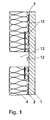
- FIG. 1 Section shown by a multilayer element according to the invention shows a thin cover plate 1 made of natural stone, on the underside of a CFRP fabric of small thickness executed as a planar reinforcement intermediate layer 2 is adhesively bonded by means of an epoxy resin.
- the thin cover plate 1 may also be made of glass, wood, metal or other stable material.
- the CFRP fabric has a high modulus of elasticity compared to the natural stone slab; The tensile and compressive strength of the CFRP fabric is significantly greater than the compressive strength of natural stone.
- a pressure-resistant foam layer made of expanded polypropylene is adhesively bonded to the surface.
- the illustrated multilayer construction achieves a high flexural strength at low weight of the multilayered element.
- An expedient embodiment provides that the reinforcement is arranged within the lightweight material layer 4.
- the introduction of reinforcing elements can advantageously also be carried out by incorporating slots or grooves for receiving strip-shaped reinforcements 2 into the lightweight material layer 4.
- the grooves can, for example, in prefabricated Lightweight panels are already incorporated before the connection with the thin cover plate 1, to subsequently glued strip-shaped reinforcements in these grooves. Slits can be achieved, for example, by gluing the lightweight panels in smaller parts with appropriate distances between them with the cover plate. 1 At all four edges of the lightweight material layer 4 of the square floor element grooves 3 are arranged, which serve to receive connecting strips 9.
- the floor elements may have edge lengths of 200 to 2200 mm, preferably squares with an edge length of 300 to 500 mm and a thickness of 10 to 40 mm are used.
- the grooves 3 are shorter than the edges of the plates, so that the lightweight material layer 4 terminates flush with the cover plate 1 at the corners.
- the grooves can be arranged directly at the interface of the cover plate 1 and the lightweight material layer 4 or also in the lightweight material layer 4 and be spaced from the interface.
- grooves 12 At the top and bottom of the lightweight material layer 4 intersecting grooves 12 are arranged, in which evaporate on the underside of the cover plates 1 forming condensation moisture and can be removed. By means of the grooves 12, it is also possible to guide atmospheric moisture arising from the substrate or water penetrating from the cover plate 1 to the edge of the floor surface.
- the grooves may lie parallel and congruent one above the other in the upper and lower sides or may also be offset from one another.
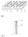
- FIG. 2 an isometric view of the element according to the invention from below, shown recesses 13, preferably the Touch grooves 12, in particular at the intersections of the grooves, warm air can be guided by a heat source located below the layer of lightweight material to the cover plate 1. Through the grooves 12, the hot air is supplied to a larger area and thus heats the cover plate 1. In this embodiment, it is expedient to use a foam of increased density, so that the lower carrying capacity is compensated by the recesses.
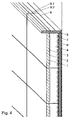
- a connection bar 9 is in FIG. 3 shown.
- the connecting bar 9 has at least two horizontal legs 9.1.
- the in the FIG. 2 illustrated embodiment is similar to a T-profile and has two horizontal legs 9.1 and an additional vertical leg 9.2.
- the thickness of the horizontal leg 9.1 is slightly smaller than the width of the grooves 3; in the longitudinal direction of the profile 9.1 profiling are arranged on the horizontal legs, which serve to clamp the horizontal leg 9.1 safely in the grooves 3 and so serve the compound adjacent arranged multilayer cover plates.
- the vertical leg 9.2 serves to maintain a defined butt joint width between the multilayer plates.
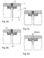
- FIG. 4 shows an isometric cutout of an overall arrangement of a floor with a plurality of interconnected by connecting strips 9 multi-layer elements.
- the multilayer elements are laid on a flat lower layer; the lower layer consists of a lower film 8 with a quick-setting floating screed 7 poured over it. Above the screed 7, an upper film 6 is arranged.
- the lateral boundary of the floor is an L-shaped, arranged metallic angle profile 5, the horizontal leg is covered with the flow screed 7. Through this overlap, the angle section 5 is fixed in the lower layer.
- On the side facing the floor of the vertical leg of the angle section 5 is provided with a compressible sealing strip, which prevents the escape of mortar from the frame.
- FIG. 5 explains a detail of a joint, in which there are additional fastening rails 10 in the side surfaces of the lightweight material layer 10, which have a groove into which the horizontal leg 9.1 of the connecting strips 9 engage.
- the horizontal leg 9.1 are formed by a slit elastic and provided at the lower ends with thickenings, which engage in corresponding, attached to the inner surfaces of the mounting rails undercuts and allow a positive but releasable connection, and so a safe and gap-free arrangement adjacent elements allows.
- the vertical leg 9.2 are provided on its upper side with a colored edge strip 11 made of an elastic plastic, which fulfills both decorative tasks and improves the seal. The surface of the edge strip 11 can be next to the in FIG.
- connection bar 9 consists only of the two horizontal legs 9.2, which are provided with openings. This makes it possible to dissipate water from the surfaces of the elements, which thereby run into the gap between adjacent elements and can be derived through the connecting bar 9 therethrough.
- the grooves 3 are generated by recesses in the lightweight material layer 4, so that the additional, expensive use of mounting rails 10 is eliminated.
- dechtstoff für 4 and the cover plate 1 further layers may be arranged, for example, a metal layer to distribute the heat of a heater even more evenly.
- the grooves 12 may be either continuous, so that, for example, form long channels in the association of several floor elements, or they may end within the surface of the lightweight material layer 4, so that they do not break the edge thereof or the grooves 3.
- cover plates are strip-shaped.
- a plurality of parallel strip-shaped individual elements 1.1 are glued on the carrier element consisting of a lightweight material layer 4.
- a lightweight material layer 4 Especially suitable for this are strips of wood.
- the individual elements can also be formed in any other forms, the attachment can be done both by gluing, as well as by means of screws, nails or other suitable connection options.
- the strip-shaped individual elements 1.1 are fastened on a carrier element that can be in the form of a plate or a frame.
- connection of adjacent elements takes place by means of connecting elements which respectively engage in grooves which are located on vertical surfaces of adjacent elements.
- the connecting elements can be arranged between the individual elements 1.1 and / or at between adjacent carrier elements.
- the connection is effected by means of a detent.
- the strip-shaped individual elements 1.1 are located on a carrier element, which consists of a pressure-resistant lightweight material layer.
- the sealing profile 1.2 consists in the case shown of a rubber strip which is reinforced for the purpose of better mountability with a plastic core and has two lateral beads which engage in grooves which are incorporated into the vertical surfaces of the wooden strips. At the upwardly projecting portion of the sealing profile 1.2 a thickening is mounted, which are in the example shown in chamfers of the individual elements 1.1. To achieve a high level of slip resistance, the sealing profile 1.2 can also protrude above the wooden strips. Of course, the sealing profile 1.2 can also be made of other materials, such as plastic or metal.
- FIG. 8 explains an embodiment in which an intermediate layer 2 of fleece is glued to the lightweight material layer 4. This layer facilitates the bonding of cover plates 1.
Landscapes
- Engineering & Computer Science (AREA)
- Architecture (AREA)
- Civil Engineering (AREA)
- Structural Engineering (AREA)
- Chemical & Material Sciences (AREA)
- Ceramic Engineering (AREA)
- Floor Finish (AREA)
Abstract
Description
Die Erfindung betrifft ein flächenhaftes, mehrschichtiges Element für Fußböden, mit einer dünnen druck- und abriebfesten Deckplatte, welche die Oberseite des mehrschichtigen Elementes bildet, und bei dem sich an der Unterseite der dünnen druck- und abriebfesten Deckplatte ein an dieser durch eine Klebverbindung befestigtes, druckfestes Trägerelement befindet, wobei in senkrechten Randflächen Nuten angeordnet sind und in den Nuten zur Verbindung benachbart verlegter mehrschichtigen Elemente Verbindungsleisten anbringbar sind.The invention relates to a laminar, multi-layer element for floors, with a thin pressure and abrasion resistant cover plate, which forms the top of the multilayer element, and in which at the bottom of the thin pressure and abrasion resistant cover plate attached to this by an adhesive bond, pressure-resistant carrier element is located, wherein in vertical edge surfaces grooves are arranged and in the grooves for connecting adjacent laid multilayer elements connecting strips are attached.
Die Erfindung ist insbesondere für wieder entfernbare und somit mehrfach verwendbare Fußböden vorgesehen. Bei wieder entfernbaren und mehrfach verwendbaren Fußböden, die beispielsweise für Ausstellungen benötigt werden, war es bisher nicht möglich, ebene und hochwertige Fußbodenflächen mit hoher Belastbarkeit, insbesondere unter Verwendung von dünnen und somit leichten Natursteinplatten zu gestalten. Selbstverständlich ist auch eine dauerhafte Verlegung möglich. Das Fußbodenelement ist auch für die Verlegung auf Fußbodenheizungen geeignet.The invention is particularly intended for removable and thus reusable floors. For removable and reusable floors, which are needed for example for exhibitions, it has not been possible to make flat and high quality floor surfaces with high load capacity, especially using thin and thus lightweight natural stone slabs. Of course, a permanent installation is possible. The floor element is also suitable for laying on underfloor heating systems.
Für die an der Oberseite angeordnete abriebfeste Deckplatte können unterschiedliche Werkstoffe eingesetzt werden. Hierzu sind beispielsweise Stein, insbesondere Naturstein, Keramik, Glas oder Kunststoff sowie Holz geeignet.Different materials can be used for the abrasion-resistant cover plate arranged on the upper side. For this example, stone, especially natural stone, ceramic, glass or plastic and wood are suitable.
Im Stand der Technik sind wieder entfernbare Fußböden für textile Beläge bekannt. Dabei soll der Belag vom Boden restlos und ohne Beschädigung des Belags wieder entfernbar sein.In the prior art removable flooring for textile coverings are known. The covering should be removable from the floor completely and without damaging the covering.
Nach
Für die Anwendung bei hohen Belastungen und im Außenbereich ist es bekannt, Stein-, Beton- oder Keramikelemente in Mörtel oder auf Stelzlagem zu verlegen. Nach
Natursteinplatten sind in der üblichen Art und Weise zur Erzielung der erforderlichen Festigkeit dick und schwer und somit umständlich zu transportieren und deshalb für mehrfache Verwendung nicht geeignet. Natursteinplatten in dünnen und somit leicht zu transportierenden Ausführungen müssen auf Grund ihrer Bruchgefahr auf einer ebenen Unterschicht verklebt oder in einem Mörtelbett verlegt werden und sind somit zur mehrfachen Verwendung ebenfalls nicht geeignet.Natural stone slabs are in the usual way to achieve the required strength thick and heavy and thus cumbersome to transport and therefore not suitable for multiple use. Natural stone slabs in thin and thus easily transportable versions must be glued on the basis of their risk of breakage on a flat bottom layer or laid in a mortar bed and are therefore also not suitable for multiple use.
In
Diese Anordnungen sind jedoch nicht geeignet, um eine sichere und exakte Anordnung der Einzelelemente zu einer Fußbodenfläche zu ermöglichen.However, these arrangements are not suitable to allow a safe and accurate arrangement of the individual elements to a floor surface.
Ferner sind nach
Nachteilig ist hierbei, dass die Ränder der druck- und abriebfesten Platte stark bruchgefährdet sind.Further, after
The disadvantage here is that the edges of the pressure and abrasion resistant plate are very vulnerable to breakage.
Aus
Die Nachteile dieses Fußbodenelements sind zum einen die parallele Ausrichtung der nutförmigen Ausnehmungen, so dass der Lufttransport darin nur in zwei entgegengesetzten Richtungen möglich ist. Zum anderen erfordert die Konstruktion das Anbringen eines zusätzlichen Nutzbelags auf der Oberfläche.Out
The disadvantages of this floor element are on the one hand the parallel alignment of the groove-shaped recesses, so that the air transport therein is possible only in two opposite directions. On the other hand, the construction requires the attachment of an additional surface covering on the surface.
Ferner ist in
Die
An diesem Fußboden ist von Nachteil, dass als Leichtstoff Styropor vorgesehen ist, welches zum einen nicht elastisch verformbar ist, so dass Untergrundunebenheiten den Fußboden dauerhaft verformen, zum anderen ist die Stabilität von Styropor nicht sehr hoch. Ein weiterer Effekt der Inelastizität ist die Härte des Fußbodens beim Begehen. Eine Fußbodenheizung unter dem Fußboden würde durch die gute Isolation zudem fast wirkungslos.On this floor is a disadvantage that is provided as a lightweight material styrofoam, which is not elastically deformable on the one hand, so that substrate bumps permanently deform the floor, on the other hand, the stability of Styrofoam is not very high. Another effect of inelasticity is the hardness of the floor when walking. Underfloor heating under the floor would also be almost ineffective due to the good insulation.
Der Erfindung liegt die Aufgabe zugrunde, eine Fußbodengestaltung hoher Festigkeit mit einzelnen Elementen anzugeben, die sowohl leicht und einfach transportierbar ist und deren Bauelemente einfach wieder entfernbar und somit mehrfach verwendbar sind, die zudem angenehm begehbar sind und den Einsatz auf Fußbodenheizungen erlauben.The invention has for its object to provide a floor design high strength with individual elements that is both easy and easy to transport and their components are easily removable and thus reusable, which are also pleasant to walk on and allow use on underfloor heating.
Erfindungsgemäß gelingt die Lösung der Aufgabe mit einem Fußbodenelement welches die im Patentanspruch 1 angegebenen Merkmale aufweist.According to the invention, the solution of the problem with a floor element which has the features specified in
Vorteilhafte Ausgestaltungen sind im Unteranspruch angegeben.Advantageous embodiments are specified in the dependent claim.
Die Erfindung weist eine Reihe von Vorteilen auf.The invention has a number of advantages.
Es können leichte Fußbodenelemente mit hochwertiger Oberfläche und ausreichender Festigkeit hergestellt werden. Dies wird erreicht durch den mehrschichtigen Aufbau der einzelnen Elemente mit mindestens einer dünnen Deckplatte an der Oberseite und einem darunter angeordneten geklebten druckfesten Trägerelement, das in Form einer Leichtstoffschicht aus expandiertem Polypropylen ausgebildet ist.It can light floor elements with high quality surface and sufficient strength are produced. This is achieved by the multilayer structure of the individual elements with at least one thin cover plate on the upper side and a glued pressure-resistant support element arranged underneath, which is designed in the form of a lightweight material layer of expanded polypropylene.
Eine vorteilhafte Ausführung entsteht dadurch, dass die an der Oberseite angebrachte abriebfeste Deckplatte aus streifenförmigen Einzelelementen, vorzugsweise in Form von Holzleisten, besteht. Dabei können zwischen den streifenförmigen Einzelelementen Streifen aus einem elastischen Material, beispielsweise aus Gummi, angeordnet werden, um eine gute Dichtigkeit zwischen einzelnen Deckplatten sowie eine Rutschsicherheit, insbesondere beim Begehen feuchter Oberflächen, erreicht werden.An advantageous embodiment results from the fact that the abrasion-resistant cover plate attached to the upper side consists of strip-shaped individual elements, preferably in the form of wooden strips. In this case, strips of an elastic material, for example made of rubber, can be arranged between the strip-shaped individual elements in order to achieve good tightness between individual cover plates as well as slip resistance, in particular when walking on moist surfaces.
Durch die Anordnung von Nuten an den Rändern der Leichtstoffschicht und durch die Anordnung von Verbindungsleisten in den Nuten zwischen jeweils benachbart verlegten mehrschichtigen Elemente gelingen auf einfache Weise sowohl eine Sicherung der Fußbodenelemente gegen Verschiebungen in Fugenrichtung als auch eine Vermeidung von Absätzen zwischen jeweils benachbart verlegten mehrschichtigen Elemente.The arrangement of grooves at the edges of the lightweight material layer and by the arrangement of connecting strips in the grooves between each adjacent laid multilayer elements succeed in a simple way both securing the floor elements against displacement in the joint direction and avoiding paragraphs between each adjacent laid multilayer elements ,
Durch Rillen in der Oberseite der Leichtstoffschicht sind die Elemente zur Ab- und Durchführung von Kondens- und Luftfeuchte und zur Zuführung von Warmluft von einer Fußbodenheizung geeignet. Durch Rillen in der Unterseite der Leichtstoffschicht ist die Ableitung von Nässe möglich. Vorzugsweise werden gekreuzte Rillen verwendet.
Vorzugsweise werden die Rillen in zwei zueinander orthogonale Richtungen angeordnet und weisen eine Tiefe von 1 bis 10 mm auf.By grooves in the top of the lightweight material layer, the elements for removing and carrying out condensation and air humidity and for supplying hot air from a floor heating are suitable. By grooves in the bottom of the lightweight material layer, the drainage of moisture is possible. Preferably, crossed grooves are used.
Preferably, the grooves are arranged in two mutually orthogonal directions and have a depth of 1 to 10 mm.
Die Erfindung sieht auch vor, dass die Nuten kürzer sind als die Elementenbreite, sodass die Ecken der Deckplatten und der Leichtstoffschicht einen flächigen Kontakt aufweisen und bündig abschließen. Hierdurch wird einerseits die Kraftübertragung an den Rändern verbessert und andererseits die Gefahr von Beschädigungen durch äußere Kräfte wie beispielsweise das Verhaken mit Werkzeugen verringert ist, was besonders bei oftmaligen Auf- und Abbau von Vorteil ist.The invention also provides that the grooves are shorter than the element width, so that the corners of the cover plates and the lightweight material layer have a flat contact and terminate flush. As a result, on the one hand, the power transmission at the edges is improved and on the other hand, the risk of damage from external forces such as snagging with tools is reduced, which is especially in frequent construction and dismantling advantage.
Senkrechte Durchbrüche an der Leichtstoffschicht ermöglichen die Zuführung von Warmluft aus unterhalb des Fußbodens gelegener Heizquellen, wobei Rillen in der Unter- und/oder Oberseite der Leichtstoffschicht, die diese Ausnehmungen berühren oder kreuzen, eine großflächige Verteilung der Warmluft ermöglichen. Zweckmäßigerweise werden diese Durchbrüche zumindest teilweise an den Kreuzungspunkten der Rillen angebracht.Vertical apertures on the lightweight material layer allow the supply of hot air from below the floor located heat sources, with grooves in the bottom and / or top of the lightweight material layer that touch or cross these recesses, allow a large-scale distribution of hot air. Conveniently, these openings are at least partially attached to the crossing points of the grooves.
Durch das Aufbringen einer dünnen Zwischenschicht auf die Leichtstoffschicht ermöglicht weitere vorteilhafte Ausführungen. Die Zwischenschicht kann dabei vollflächig oder in Teilbereichen aufgeklebt sein. Sie kann als Bewehrungselement mit hoher Festigkeit und hohem Elastizitätsmodul ausgeführt werden, sodass selbst bei Verwendung sehr dünner Deckplatten und somit sehr leichter Fußbodenelemente eine sehr hohe Festigkeit der Fußbodenelemente erzielt wird, die eine ausreichende Bruchsicherheit selbst bei hohen punktuellen Beanspruchungen, die zum Beispiel bei der Aufstellung von punktgestützten Regalen oder Schränken auftreten, gewährleisten, ohne dass eine Verlegung der Fußbodenelemente in einem Mörtelbett oder ein Verkleben der Fußbodenelemente mit einer Unterschicht erforderlich ist. Das Bewehrungselement kann vollflächig oder streifenförmig angeordnet werden und aus CFK, CFK-Gewebe, Glasfaser oder Metall bestehen. Es ist auch möglich, dass die Bewehrung innerhalb der Leichtstoffschicht angeordnet ist.
Vorteilhaft sind hierzu in der Leichtstoffschicht Schlitze oder Nuten zur Aufnahme streifenförmiger Bewehrungen eingearbeitet.By applying a thin intermediate layer on the lightweight material layer allows further advantageous embodiments. The intermediate layer can be glued over the entire surface or in some areas. It can be designed as a reinforcing element with high strength and high modulus of elasticity, so that even when using very thin cover plates and thus very light floor elements a very high strength of the floor elements is achieved, the sufficient resistance to breakage even at high punctual loads, for example when installing from point-based shelving or cabinets, without requiring laying of the floor elements in a mortar bed or gluing of the floor elements with a sub-layer. The reinforcing element can be arranged over the entire surface or in strips and made of CFRP, CFRP fabric, glass fiber or Metal exist. It is also possible that the reinforcement is arranged within the lightweight material layer.
For this purpose, slits or grooves for receiving strip-like reinforcements are advantageously incorporated in the lightweight material layer.
Zur Verbesserung der Haftfähigkeit und zur Erleichterung des Anbringens der Deckplatten kann die Zwischenschicht auch als eine mit der Leichtstoffschicht verklebte Schicht aus Vlies, Papier und dergleichen ausgeführt werden.In order to improve the adhesiveness and to facilitate the attachment of the cover plates, the intermediate layer can also be designed as a layer of fleece, paper and the like bonded to the lightweight material layer.
Ferner ist es möglich, dass die Leichtstoffschicht an ihrer Oberseite durch Wärmeeinwirkung behandelt wird, so dass eine Teilschicht entsteht, auf der die Deckplatten in einfacher Weise guthaftend verklebt werden können.Further, it is possible that the lightweight material layer is treated on its upper side by the action of heat, so that a partial layer is formed, on which the cover plates can be glued good adhesion in a simple manner.
Die Erfindung wird im Folgenden an einem Ausführungsbeispiel näher erläutert. In den zugehörigen Zeichnungen zeigen:
-
Figur 1 - einen Schnitt durch ein erfindungsgemäßes mehrschichtiges Fussbodenelement,
-
Figur 2 - ein erfindungsgemäßes, mehrschichtiges Element von unten gesehen,
-
Figur 3 - eine Verbindungsleiste,
-
Figur 4 - einen Ausschnitt aus einer Gesamtanordnung eines Fußbodens,
-
Figur 5 - eine Einzelheit der Verbindungsstelle
-
Figur 6 - eine Ausführung mit streifenförmigen Deckplatten,
- Figur 7
- die Anordnung eines Dichtprofils zwischen streifenförmigen Deckplatten
und -
Figur 8 - eine Ausführung mit Vlieszwischenschicht.
- FIG. 1
- a section through a multilayer floor element according to the invention,
- FIG. 2
- an inventive multilayer element seen from below,
- FIG. 3
- a connection bar,
- FIG. 4
- a section of an overall arrangement of a floor,
- FIG. 5
- a detail of the junction
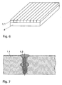
- FIG. 6
- a version with strip-shaped cover plates,
- FIG. 7
- the arrangement of a sealing profile between strip-shaped cover plates
and - FIG. 8
- a version with fleece interlayer.
Der in
An allen vier Rändern der Leichtstoffschicht 4 des quadratischen Fußbodenelementes sind Nuten 3 angeordnet, die der Aufnahme von Verbindungsleisten 9 dienen. Die Fußbodenelemente können Kantenlängen von 200 bis 2200 mm aufweisen, vorzugsweise werden Quadrate mit einer Kantenlänge von 300 bis 500 mm und einer Dicke von 10 bis 40 mm verwendet. Die Nuten 3 sind kürzer als die Kanten der Platten, so dass die Leichtstoffschicht 4 an den Ecken bündig mit der Deckplatte 1 abschließt.
Die Nuten können direkt an der Grenzfläche von Deckplatte 1 und Leichtstoffschicht 4 oder auch in der Leichtstoffschicht 4 angeordnet und von der Grenzfläche beabstandet sein.The in
At all four edges of the
The grooves can be arranged directly at the interface of the
An Ober- und Unterseite der Leichtstoffschicht 4 sind sich kreuzende Rillen 12 angeordnet, in denen sich an der Unterseite der Deckplatten 1 bildende Kondensationsfeuchte verdunsten und abtransportiert werden kann. Durch die Rillen 12 kann ebenso durch den Untergrund entstehende Luftfeuchte oder von der Deckplatte 1 her eindringendes Wasser zum Rand der Fußbodenfläche geführt werden.At the top and bottom of the
Die Rillen können in Ober- und Unterseite parallel und kongruent übereinander liegen oder auch zueinander versetzt sein.The grooves may lie parallel and congruent one above the other in the upper and lower sides or may also be offset from one another.
Mit den in
In dieser Ausführung ist es zweckmäßig, die einen Schaumstoffes erhöhter Dichte einzusetzen, so dass die durch die Ausnehmungen geringere Tragkraft ausgeglichen wird.With the in
In this embodiment, it is expedient to use a foam of increased density, so that the lower carrying capacity is compensated by the recesses.
Eine Verbindungsleiste 9 ist in
Dabei ist es auch möglich, dass die vertikalen Schenkel 9.2 an ihrer Oberseite mit einer farbigen Kantenleiste 11 aus einem elastischen Kunststoff versehen sind, die sowohl dekorative Aufgaben erfüllt als auch die Abdichtung verbessert. Die Oberfläche der Kantenleiste 11 kann neben der in
It is also possible that the vertical leg 9.2 are provided on its upper side with a
Vorzugsweise werden die Nuten 3 durch Ausnehmungen in der Leichtstoffschicht 4 erzeugt, so dass die zusätzliche, aufwendige Verwendung von Befestigungsschienen 10 entfällt.Preferably, the
Bei Nuten, die von der Grenzfläche beabstandet sind, ist es sinnvoll, auch an der Oberseite der Nuten 3 Hinterschneidungen anzubringen und die Verbindungsleisten 9 an den horizontalen Schenkel ebenfalls mit Verdickungen zu versehen.For grooves, which are spaced from the interface, it makes sense to also attach to the top of the
Zwischen de Leichtstoffschicht 4 und der Deckplatte 1 können weitere Schichten angeordnet sein, beispielsweise eine Metallschicht, um die Wärme einer Heizung noch gleichmäßiger zu verteilen.Between
Die Rillen 12 können entweder durchgängig gestaltet sein, so dass sich im Verband mehrerer Fußbodenelemente beispielsweise lange Kanäle bilden, oder sie können innerhalb der Oberfläche der Leichtstoffschicht 4 enden, so dass sie den Rand derselben bzw. der Nuten 3 nicht durchbrechen.The
In
Die streifenförmigen Einzelelemente 1.1 werden auf einem Trägerelement befestigt, dass in Form einer Platte oder eines Rahmen ausgebildet sein kann.The strip-shaped individual elements 1.1 are fastened on a carrier element that can be in the form of a plate or a frame.
Die Verbindung benachbarter Elemente erfolgt durch Verbindungselemente, die jeweils in Nuten eingreifen, welche sich an senkrechten Flächen benachbarter Elemente befinden. Die Verbindungselemente können zwischen den Einzelelementen 1.1 und/oder an zwischen benachbarten Trägerelementen angeordnet sein. Vorzugsweise erfolgt die Verbindung mittels einer Rastung.The connection of adjacent elements takes place by means of connecting elements which respectively engage in grooves which are located on vertical surfaces of adjacent elements. The connecting elements can be arranged between the individual elements 1.1 and / or at between adjacent carrier elements. Preferably, the connection is effected by means of a detent.
Bei einer bevorzugten Ausführung befinden sich die streifenförmigen Einzelelemente 1.1 auf einem Trägerelement, das aus einer druckfesten Leichtstoffschicht besteht.In a preferred embodiment, the strip-shaped individual elements 1.1 are located on a carrier element, which consists of a pressure-resistant lightweight material layer.
Bei der in
Das Dichtprofil 1.2 kann natürlich auch aus anderen Materialien, beispielsweise aus Kunststoff oder Metall bestehen.At the in
Of course, the sealing profile 1.2 can also be made of other materials, such as plastic or metal.
- 11
-
Deckplatte
1.1 streifenförmiges Einzelelement
1.2 Dichtprofilcover plate
1.1 strip-shaped single element
1.2 sealing profile - 22
- Zwischenschichtinterlayer
- 33
- Nutgroove
- 44
- LeichtstoffschichtLightweight material layer
- 55
- Winkelprofilangle section
- 66
- obere Folieupper foil
- 77
- Fließestrichleveling screed
- 88th
- untere Folielower foil
- 99
-
Verbindungsleiste
9.1 horizontale Schenkel
9.2 vertikaler Schenkelconnecting strip
9.1 horizontal legs
9.2 vertical leg - 1010
- Befestigungsschienemounting rail
- 1111
- Kantenleistelipping
- 1212
- Rillegroove
- 1313
- Ausnehmungrecess
Claims (2)
- Planar multilayered element for floors, having a thin pressure-resistant and abrasion-resistant top panel (1) which forms the top side of the multilayered element, and in which a pressure-resistant carrier element is located at the lower side of the thin pressure-resistant and abrasion-resistant top panel (1) and fastened to the latter by an adhesive bond, while slots (3) are arranged in vertical lateral faces and joining bars (9) are attachable in the slots (3) for joining multilayered elements laid contiguously,
characterized in that,- the carrier element consists of a pressure-resistant light-weight material layer (4) made of expanding polypropylene, and in that- the grooves are arranged in the light-weight material layer (4) and present a length which is shorter than the corresponding edge length of the carrier element while the carrier element and the top panel (1) rest flush on one another, except for interfacial unevenness, outside the grooves (3). - Planar element as claimed in claim 1, characterized in that the carrier element presents grooves (12) at its bottom and/or top sides.
Applications Claiming Priority (6)
| Application Number | Priority Date | Filing Date | Title |
|---|---|---|---|
| DE20314548U | 2003-09-18 | ||
| PCT/DE2003/003357 WO2005035906A1 (en) | 2003-09-18 | 2003-09-18 | Heatable floor element having a surface layer |
| WOPCT/DE03/03357 | 2003-09-18 | ||
| DE20314548 | 2003-09-18 | ||
| DE202004013987U DE202004013987U1 (en) | 2004-09-06 | 2004-09-06 | Multilayer element for floors for exhibits comprises a thin compression- and abrasion-proof covering plate on its upper side fixed to a compression-proof support element below the covering plate |
| DE202004013987U | 2004-09-06 |
Publications (3)
| Publication Number | Publication Date |
|---|---|
| EP1516976A2 EP1516976A2 (en) | 2005-03-23 |
| EP1516976A3 EP1516976A3 (en) | 2006-07-05 |
| EP1516976B1 true EP1516976B1 (en) | 2010-01-20 |
Family
ID=34195908
Family Applications (1)
| Application Number | Title | Priority Date | Filing Date |
|---|---|---|---|
| EP04021868A Expired - Lifetime EP1516976B1 (en) | 2003-09-18 | 2004-09-15 | Multilayered floor covering element with grooves for connecting profiles |
Country Status (3)
| Country | Link |
|---|---|
| EP (1) | EP1516976B1 (en) |
| AT (1) | ATE455911T1 (en) |
| DE (1) | DE502004010666D1 (en) |
Families Citing this family (1)
| Publication number | Priority date | Publication date | Assignee | Title |
|---|---|---|---|---|
| WO2019137824A1 (en) * | 2018-01-15 | 2019-07-18 | Josef Stengel | Method for producing a wall lining or floor covering |
Family Cites Families (7)
| Publication number | Priority date | Publication date | Assignee | Title |
|---|---|---|---|---|
| NL7316287A (en) * | 1973-12-07 | 1975-05-30 | Mallinson & Mott Ltd | BUILDING PANEL AND THE MANUFACTURE OF A BUILDING PANEL. |
| JPS62264253A (en) * | 1986-05-08 | 1987-11-17 | ジヤパンインテリアプランニング株式会社 | Tile material and manufacture thereof |
| AT396232B (en) * | 1988-12-07 | 1993-07-26 | Wolfgang Lehner | METHOD FOR COATING FURNITURE, WALLS AND FLOORS WITH THIN NATURAL OR ARTIFICIAL LAYER LAYERS |
| JPH11324291A (en) * | 1998-05-08 | 1999-11-26 | Kanegafuchi Chem Ind Co Ltd | Sound-insulating floor structure for building construction |
| DE10201905B4 (en) * | 2001-03-26 | 2004-07-08 | Peter Kellner | Floor made of individual elements |
| DE10133813A1 (en) * | 2001-05-20 | 2005-01-13 | Fagerdala Deutschland Gmbh | Surface treatment of cut foam plastic panels comprises pressing glued paper sheets on to their surfaces |
| WO2005035906A1 (en) * | 2003-09-18 | 2005-04-21 | Peter Kellner | Heatable floor element having a surface layer |
-
2004
- 2004-09-15 AT AT04021868T patent/ATE455911T1/en not_active IP Right Cessation
- 2004-09-15 EP EP04021868A patent/EP1516976B1/en not_active Expired - Lifetime
- 2004-09-15 DE DE502004010666T patent/DE502004010666D1/en not_active Expired - Lifetime
Also Published As
| Publication number | Publication date |
|---|---|
| DE502004010666D1 (en) | 2010-03-11 |
| EP1516976A2 (en) | 2005-03-23 |
| ATE455911T1 (en) | 2010-02-15 |
| EP1516976A3 (en) | 2006-07-05 |
Similar Documents
| Publication | Publication Date | Title |
|---|---|---|
| EP1911905B1 (en) | Multi-layer construction system for floor coverings with floor heating | |
| DE102008044803B4 (en) | A flooring system | |
| EP1490565A1 (en) | Laying system for floor tiles | |
| EP1373658B1 (en) | Multi-layered floor element | |
| DE20107338U1 (en) | Flexible floor covering system | |
| DE19828607A1 (en) | Structure increasing loading capacity of concrete floors | |
| WO2004018798A2 (en) | Floor made from individual elements | |
| DE102006035135A1 (en) | Burl component for managing requirements for surface drainage, for impact sound insulation or for distribution of load and for adhesive-free attachment of winding or floor mats, has multiple plastic burls, which are connected by bars | |
| DE202009003690U1 (en) | isolation mat | |
| DE10249493B4 (en) | Floor construction system for ceramic, tile and slab coverings | |
| WO2005035906A1 (en) | Heatable floor element having a surface layer | |
| EP1630321A2 (en) | Laying mat for tiles and method of laying tiles | |
| EP1516976B1 (en) | Multilayered floor covering element with grooves for connecting profiles | |
| WO2004042166A1 (en) | Flat board for covering floors, walls and sealing, for separating partitions and furniture | |
| DE20215223U1 (en) | Abrasion resistant reusable flooring tiles has a thin upper layer bonded to a thicker elastic layer with the layers offset to/ provide protruding edges along two sides to interlock with other similar tiles | |
| DE202004015283U1 (en) | Areal, multilayered floor element comprises at least one thin, pressure and wear resistant cover plate on top of a pressure resistant carrier layer whose edge surfaces are provided with grooves | |
| DE3925742C2 (en) | Sports hall floor | |
| DE202004013987U1 (en) | Multilayer element for floors for exhibits comprises a thin compression- and abrasion-proof covering plate on its upper side fixed to a compression-proof support element below the covering plate | |
| DE202014104792U1 (en) | Support arrangement for electric heating cables of a surface heating | |
| DE10061477B4 (en) | Prefabricated, large-format plate-shaped component | |
| DE102006053706B4 (en) | Floor construction system for raised floor coverings and method for assembling the system | |
| DE4343372A1 (en) | Wooden-plank floor with tongue-and-groove joints | |
| DE102004022446B4 (en) | Prefabricated, large-format, plate-shaped component | |
| EP0405108A1 (en) | L-formed edging strip | |
| DE20018439U1 (en) | Floor slab |
Legal Events
| Date | Code | Title | Description |
|---|---|---|---|
| PUAI | Public reference made under article 153(3) epc to a published international application that has entered the european phase |
Free format text: ORIGINAL CODE: 0009012 |
|
| AK | Designated contracting states |
Kind code of ref document: A2 Designated state(s): AT BE BG CH CY CZ DE DK EE ES FI FR GB GR HU IE IT LI LU MC NL PL PT RO SE SI SK TR |
|
| AX | Request for extension of the european patent |
Extension state: AL HR LT LV MK |
|
| 17P | Request for examination filed |
Effective date: 20050526 |
|
| PUAL | Search report despatched |
Free format text: ORIGINAL CODE: 0009013 |
|
| AK | Designated contracting states |
Kind code of ref document: A3 Designated state(s): AT BE BG CH CY CZ DE DK EE ES FI FR GB GR HU IE IT LI LU MC NL PL PT RO SE SI SK TR |
|
| AX | Request for extension of the european patent |
Extension state: AL HR LT LV MK |
|
| 17Q | First examination report despatched |
Effective date: 20061123 |
|
| AKX | Designation fees paid |
Designated state(s): AT BE BG CH CY CZ DE DK EE ES FI FR GB GR HU IE IT LI LU MC NL PL PT RO SE SI SK TR |
|
| 17Q | First examination report despatched |
Effective date: 20061123 |
|
| GRAP | Despatch of communication of intention to grant a patent |
Free format text: ORIGINAL CODE: EPIDOSNIGR1 |
|
| GRAS | Grant fee paid |
Free format text: ORIGINAL CODE: EPIDOSNIGR3 |
|
| GRAA | (expected) grant |
Free format text: ORIGINAL CODE: 0009210 |
|
| AK | Designated contracting states |
Kind code of ref document: B1 Designated state(s): AT BE BG CH CY CZ DE DK EE ES FI FR GB GR HU IE IT LI LU MC NL PL PT RO SE SI SK TR |
|
| REG | Reference to a national code |
Ref country code: GB Ref legal event code: FG4D Free format text: NOT ENGLISH |
|
| REG | Reference to a national code |
Ref country code: CH Ref legal event code: EP |
|
| REG | Reference to a national code |
Ref country code: IE Ref legal event code: FG4D |
|
| REF | Corresponds to: |
Ref document number: 502004010666 Country of ref document: DE Date of ref document: 20100311 Kind code of ref document: P |
|
| REG | Reference to a national code |
Ref country code: NL Ref legal event code: VDEP Effective date: 20100120 |
|
| PG25 | Lapsed in a contracting state [announced via postgrant information from national office to epo] |
Ref country code: NL Free format text: LAPSE BECAUSE OF FAILURE TO SUBMIT A TRANSLATION OF THE DESCRIPTION OR TO PAY THE FEE WITHIN THE PRESCRIBED TIME-LIMIT Effective date: 20100120 Ref country code: ES Free format text: LAPSE BECAUSE OF FAILURE TO SUBMIT A TRANSLATION OF THE DESCRIPTION OR TO PAY THE FEE WITHIN THE PRESCRIBED TIME-LIMIT Effective date: 20100501 Ref country code: PT Free format text: LAPSE BECAUSE OF FAILURE TO SUBMIT A TRANSLATION OF THE DESCRIPTION OR TO PAY THE FEE WITHIN THE PRESCRIBED TIME-LIMIT Effective date: 20100520 |
|
| REG | Reference to a national code |
Ref country code: IE Ref legal event code: FD4D |
|
| PG25 | Lapsed in a contracting state [announced via postgrant information from national office to epo] |
Ref country code: PL Free format text: LAPSE BECAUSE OF FAILURE TO SUBMIT A TRANSLATION OF THE DESCRIPTION OR TO PAY THE FEE WITHIN THE PRESCRIBED TIME-LIMIT Effective date: 20100120 Ref country code: SI Free format text: LAPSE BECAUSE OF FAILURE TO SUBMIT A TRANSLATION OF THE DESCRIPTION OR TO PAY THE FEE WITHIN THE PRESCRIBED TIME-LIMIT Effective date: 20100120 Ref country code: FI Free format text: LAPSE BECAUSE OF FAILURE TO SUBMIT A TRANSLATION OF THE DESCRIPTION OR TO PAY THE FEE WITHIN THE PRESCRIBED TIME-LIMIT Effective date: 20100120 |
|
| PG25 | Lapsed in a contracting state [announced via postgrant information from national office to epo] |
Ref country code: IE Free format text: LAPSE BECAUSE OF FAILURE TO SUBMIT A TRANSLATION OF THE DESCRIPTION OR TO PAY THE FEE WITHIN THE PRESCRIBED TIME-LIMIT Effective date: 20100120 Ref country code: GR Free format text: LAPSE BECAUSE OF FAILURE TO SUBMIT A TRANSLATION OF THE DESCRIPTION OR TO PAY THE FEE WITHIN THE PRESCRIBED TIME-LIMIT Effective date: 20100421 Ref country code: CY Free format text: LAPSE BECAUSE OF FAILURE TO SUBMIT A TRANSLATION OF THE DESCRIPTION OR TO PAY THE FEE WITHIN THE PRESCRIBED TIME-LIMIT Effective date: 20100120 Ref country code: EE Free format text: LAPSE BECAUSE OF FAILURE TO SUBMIT A TRANSLATION OF THE DESCRIPTION OR TO PAY THE FEE WITHIN THE PRESCRIBED TIME-LIMIT Effective date: 20100120 Ref country code: SE Free format text: LAPSE BECAUSE OF FAILURE TO SUBMIT A TRANSLATION OF THE DESCRIPTION OR TO PAY THE FEE WITHIN THE PRESCRIBED TIME-LIMIT Effective date: 20100120 Ref country code: RO Free format text: LAPSE BECAUSE OF FAILURE TO SUBMIT A TRANSLATION OF THE DESCRIPTION OR TO PAY THE FEE WITHIN THE PRESCRIBED TIME-LIMIT Effective date: 20100120 |
|
| PLBE | No opposition filed within time limit |
Free format text: ORIGINAL CODE: 0009261 |
|
| STAA | Information on the status of an ep patent application or granted ep patent |
Free format text: STATUS: NO OPPOSITION FILED WITHIN TIME LIMIT |
|
| PG25 | Lapsed in a contracting state [announced via postgrant information from national office to epo] |
Ref country code: CZ Free format text: LAPSE BECAUSE OF FAILURE TO SUBMIT A TRANSLATION OF THE DESCRIPTION OR TO PAY THE FEE WITHIN THE PRESCRIBED TIME-LIMIT Effective date: 20100120 Ref country code: SK Free format text: LAPSE BECAUSE OF FAILURE TO SUBMIT A TRANSLATION OF THE DESCRIPTION OR TO PAY THE FEE WITHIN THE PRESCRIBED TIME-LIMIT Effective date: 20100120 Ref country code: BG Free format text: LAPSE BECAUSE OF FAILURE TO SUBMIT A TRANSLATION OF THE DESCRIPTION OR TO PAY THE FEE WITHIN THE PRESCRIBED TIME-LIMIT Effective date: 20100420 |
|
| PGFP | Annual fee paid to national office [announced via postgrant information from national office to epo] |
Ref country code: FR Payment date: 20100930 Year of fee payment: 7 |
|
| 26N | No opposition filed |
Effective date: 20101021 |
|
| PGFP | Annual fee paid to national office [announced via postgrant information from national office to epo] |
Ref country code: GB Payment date: 20100924 Year of fee payment: 7 |
|
| PG25 | Lapsed in a contracting state [announced via postgrant information from national office to epo] |
Ref country code: DK Free format text: LAPSE BECAUSE OF FAILURE TO SUBMIT A TRANSLATION OF THE DESCRIPTION OR TO PAY THE FEE WITHIN THE PRESCRIBED TIME-LIMIT Effective date: 20100120 |
|
| PGFP | Annual fee paid to national office [announced via postgrant information from national office to epo] |
Ref country code: DE Payment date: 20101125 Year of fee payment: 7 |
|
| BERE | Be: lapsed |
Owner name: KELLNER, PETER Effective date: 20100930 |
|
| PG25 | Lapsed in a contracting state [announced via postgrant information from national office to epo] |
Ref country code: IT Free format text: LAPSE BECAUSE OF FAILURE TO SUBMIT A TRANSLATION OF THE DESCRIPTION OR TO PAY THE FEE WITHIN THE PRESCRIBED TIME-LIMIT Effective date: 20100120 |
|
| PG25 | Lapsed in a contracting state [announced via postgrant information from national office to epo] |
Ref country code: MC Free format text: LAPSE BECAUSE OF NON-PAYMENT OF DUE FEES Effective date: 20100930 |
|
| REG | Reference to a national code |
Ref country code: CH Ref legal event code: PL |
|
| PG25 | Lapsed in a contracting state [announced via postgrant information from national office to epo] |
Ref country code: LI Free format text: LAPSE BECAUSE OF NON-PAYMENT OF DUE FEES Effective date: 20100930 Ref country code: CH Free format text: LAPSE BECAUSE OF NON-PAYMENT OF DUE FEES Effective date: 20100930 Ref country code: BE Free format text: LAPSE BECAUSE OF NON-PAYMENT OF DUE FEES Effective date: 20100930 |
|
| PG25 | Lapsed in a contracting state [announced via postgrant information from national office to epo] |
Ref country code: AT Free format text: LAPSE BECAUSE OF NON-PAYMENT OF DUE FEES Effective date: 20100915 |
|
| GBPC | Gb: european patent ceased through non-payment of renewal fee |
Effective date: 20110915 |
|
| REG | Reference to a national code |
Ref country code: FR Ref legal event code: ST Effective date: 20120531 |
|
| REG | Reference to a national code |
Ref country code: DE Ref legal event code: R119 Ref document number: 502004010666 Country of ref document: DE Effective date: 20120403 |
|
| PG25 | Lapsed in a contracting state [announced via postgrant information from national office to epo] |
Ref country code: DE Free format text: LAPSE BECAUSE OF NON-PAYMENT OF DUE FEES Effective date: 20120403 |
|
| PG25 | Lapsed in a contracting state [announced via postgrant information from national office to epo] |
Ref country code: FR Free format text: LAPSE BECAUSE OF NON-PAYMENT OF DUE FEES Effective date: 20110930 Ref country code: GB Free format text: LAPSE BECAUSE OF NON-PAYMENT OF DUE FEES Effective date: 20110915 |
|
| PG25 | Lapsed in a contracting state [announced via postgrant information from national office to epo] |
Ref country code: LU Free format text: LAPSE BECAUSE OF NON-PAYMENT OF DUE FEES Effective date: 20100915 Ref country code: HU Free format text: LAPSE BECAUSE OF FAILURE TO SUBMIT A TRANSLATION OF THE DESCRIPTION OR TO PAY THE FEE WITHIN THE PRESCRIBED TIME-LIMIT Effective date: 20100721 |
|
| PG25 | Lapsed in a contracting state [announced via postgrant information from national office to epo] |
Ref country code: TR Free format text: LAPSE BECAUSE OF FAILURE TO SUBMIT A TRANSLATION OF THE DESCRIPTION OR TO PAY THE FEE WITHIN THE PRESCRIBED TIME-LIMIT Effective date: 20100120 |