EP1516795B1 - System für das Regeln der Leistungsversorgung eines Bremssystems - Google Patents
System für das Regeln der Leistungsversorgung eines Bremssystems Download PDFInfo
- Publication number
- EP1516795B1 EP1516795B1 EP04104466A EP04104466A EP1516795B1 EP 1516795 B1 EP1516795 B1 EP 1516795B1 EP 04104466 A EP04104466 A EP 04104466A EP 04104466 A EP04104466 A EP 04104466A EP 1516795 B1 EP1516795 B1 EP 1516795B1
- Authority
- EP
- European Patent Office
- Prior art keywords
- driven
- input
- engine
- brake
- power source
- Prior art date
- Legal status (The legal status is an assumption and is not a legal conclusion. Google has not performed a legal analysis and makes no representation as to the accuracy of the status listed.)
- Expired - Lifetime
Links
- 230000001105 regulatory effect Effects 0.000 title claims description 12
- 239000012530 fluid Substances 0.000 claims description 24
- 230000005611 electricity Effects 0.000 claims description 18
- 238000010586 diagram Methods 0.000 description 9
- 230000001276 controlling effect Effects 0.000 description 2
- 230000000694 effects Effects 0.000 description 2
- 238000006243 chemical reaction Methods 0.000 description 1
- 230000007812 deficiency Effects 0.000 description 1
- 230000002401 inhibitory effect Effects 0.000 description 1
- 239000000463 material Substances 0.000 description 1
- 238000004064 recycling Methods 0.000 description 1
Images


Classifications
-
- B—PERFORMING OPERATIONS; TRANSPORTING
- B60—VEHICLES IN GENERAL
- B60T—VEHICLE BRAKE CONTROL SYSTEMS OR PARTS THEREOF; BRAKE CONTROL SYSTEMS OR PARTS THEREOF, IN GENERAL; ARRANGEMENT OF BRAKING ELEMENTS ON VEHICLES IN GENERAL; PORTABLE DEVICES FOR PREVENTING UNWANTED MOVEMENT OF VEHICLES; VEHICLE MODIFICATIONS TO FACILITATE COOLING OF BRAKES
- B60T13/00—Transmitting braking action from initiating means to ultimate brake actuator with power assistance or drive; Brake systems incorporating such transmitting means, e.g. air-pressure brake systems
- B60T13/10—Transmitting braking action from initiating means to ultimate brake actuator with power assistance or drive; Brake systems incorporating such transmitting means, e.g. air-pressure brake systems with fluid assistance, drive, or release
- B60T13/66—Electrical control in fluid-pressure brake systems
-
- B—PERFORMING OPERATIONS; TRANSPORTING
- B60—VEHICLES IN GENERAL
- B60T—VEHICLE BRAKE CONTROL SYSTEMS OR PARTS THEREOF; BRAKE CONTROL SYSTEMS OR PARTS THEREOF, IN GENERAL; ARRANGEMENT OF BRAKING ELEMENTS ON VEHICLES IN GENERAL; PORTABLE DEVICES FOR PREVENTING UNWANTED MOVEMENT OF VEHICLES; VEHICLE MODIFICATIONS TO FACILITATE COOLING OF BRAKES
- B60T13/00—Transmitting braking action from initiating means to ultimate brake actuator with power assistance or drive; Brake systems incorporating such transmitting means, e.g. air-pressure brake systems
- B60T13/10—Transmitting braking action from initiating means to ultimate brake actuator with power assistance or drive; Brake systems incorporating such transmitting means, e.g. air-pressure brake systems with fluid assistance, drive, or release
Definitions
- the present invention relates to system of regulating the rate at which power is supplied to a brake system. More specifically, the invention relates to a system employing a controller and an intermediate device, which is driven by an engine and which drives a brake power source, to regulate the rate at which the power source supplies power to the brake system.
- a moving vehicle possesses kinetic energy, which must be removed in order for the vehicle to slow or stop. This removal of kinetic energy is most generally achieved by converting this energy into heat via friction.
- This additional frictional force must be applied.
- This additional conversion of kinetic energy into heat is usually performed by applying a contact material-typically in the form of a block or a pad-to the rotating wheels or to discs attached to the axles. As friction is created and the kinetic energy is thereby converted into heat, the wheels slow down and eventually the vehicle stops.
- Systems for supplying power to a brake system are also generally well known, and typically include a power source, such as a compressor or an electric generator, that is driven by the crankshaft of the vehicle's engine.
- a power source such as a compressor or an electric generator
- Such an arrangement allows power to be continuously available, which may be required for a variety of reasons. For example, in cases where the power is utilized to engage the braking mechanism, such as by causing a caliper to pinch a rotating disc, a driver who wants to brake often or immediately on demand will always have the appropriate power available to power the caliper.
- a system for regulating the supply of power to a vehicle's brake system comprising an engine, a brake power source, a brake system powered by said power source and a controller.
- Such known brake system comprises a shaft portion which is driven by an engine and sensed by a sensor pick-up which provides its signals to an electronic control means.
- the electronic control means produces control signals which actuate electromagnetic valves.
- a pressure accumulator is loaded by a pump which is driven by the engine.
- the control valves are interconnected between the pressure accumulator and a brake cylinder.
- EP-A-0 849 134 discloses an engine operated brake system comprising a hydraulic pump driven by an engine, and a valve assembly for controlling hydraulic fluid streams from the pump to wheel cylinders.
- the invention comprises a system for regulating the supply of power to a vehicle's brake system, including an engine, an intermediary device driven by the engine, a brake power source driven by the intermediary device, a brake system powered by the brake power source, and a controller in communication with the intermediary device, the controller, in response to a minimum engine speed, causing the intermediary device to drive the brake power source at a desired rate.
- the invention comprises a system for regulating the supply of power to a vehicle's brake system, including an engine, an intermediary device driven by the engine, a source of pressurized fluid driven by the intermediary device, a brake system powered by the source of pressurized fluid, and an electronic control unit in communication with the intermediary device, the controller, in response to a minimum engine speed, causing the intermediary device to drive the source of pressurized fluid at a desired rate.
- the invention comprises a system for regulating the supply of power to a vehicle's brake system, including an engine, an intermediary device driven by the engine, a source of electricity driven by the intermediary device, a brake system powered by the source of electricity, and an electronic control unit in communication with the intermediary device, the controller, in response to a minimum engine speed, causing the intermediary device to drive the source of electricity at a desired rate.
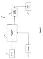
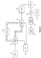
- Figure 1 is a block diagram of a system for regulating the supply of power to a brake system in accordance with the invention.
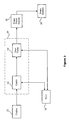
- FIG. 2 is a block diagram of one specific embodiment of the system of Figure 1.
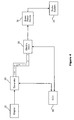
- FIG. 3 is a block diagram of another specific embodiment of the system of Figure 1.
- Figure 4 is a block diagram of another specific embodiment of the system of Figure 2.
- FIG. 5 is a block diagram of another specific embodiment of the system of Figure 2.
- Figure 6 is a block diagram of a specific embodiment of the system of Figure 5.
- FIG. 7 is a block diagram of another specific embodiment of the system of Figure 5.
- Figure 8 is a block diagram of a specific embodiment of the system of Figure 5.
- Figure 9 is a block diagram of a specific embodiment of the system of Figure 8.
- the system 20 includes an engine 22, which drives an intermediate device 24, usually via crankshaft (not shown).
- the intermediate device 24, drives a brake power source 26, which supplies power to a brake system 28.
- a controller 30 communicates with the intermediate device 24 in order to regulate the rate at which the intermediate device drives the brake power source 26.
- the brake power source 26 though ultimately driven by the crankshaft of the engine 22, need not necessarily be driven at the same speed at which the crankshaft turns. Accordingly, the controller 30 can, in response to a minimum engine speed, cause the intermediate device 24 to drive the brake power source 26 at a desired rate.
- the controller 30 is an electronic control unit (ECU).
- ECU electronice control unit
- an operator of the vehicle can effect complete control over the electronic control unit 30, and thus, can directly regulate the rate at which the intermediate device 24 drives the brake power source 26.
- the electronic control unit 30 has one or more inputs that effect the rate at which the brake power source 26 is driven, as is further explained below.
- the intermediate device 24 includes two separately housed components.
- the basic components of one such embodiment of the intermediate device 24 are illustrated in Figure 2.
- the intermediate device 24 includes a supply device 40 and a motor 42.
- the supply device 40 which is driven by the crankshaft of the engine 22, supplies an agency (indicated by arrows A), such as fluid or electricity, to the motor 42.
- the motor 42 which is driven by the agency, in turn, drives the brake power source 26. Accordingly, by regulating the amount of the agency that is supplied to the motor 42 by the device 40, the rate at which the brake power source 26 is driven is controlled.
- FIG. 3 The basic components of another intermediate device 24 including two separately house components is illustrated in Figure 3.
- This embodiment employs an arrangement of at least two gear trains 50 that are capable of driving the brake power source 26.
- the crankshaft of the engine 22 is connectable to the gear trains via a clutch 52, thereby enabling a switch between the different gear trains 50.
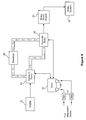
- the arrangement in Figure 2 may take one of several different forms.
- the supply device may be a generator 60 for supplying electricity.
- the motor is an electric motor 62, which is driven by the electricity supplied by the generator 60.
- the supply device may be a hydraulic pump 64 for supplying a fluid.
- the motor is a hydraulic motor, which is driven by the fluid supplied by the hydraulic pump.
- the fluid is repeatedly returned to the hydraulic pump 64 (indicated by arrows B) for continued use by the hydraulic pump 64 to drive the hydraulic motor 66.
- a reservoir 68 is provided in order to further facilitate the recycling of fluid in this manner.
- the electronic control unit 30 regulates the operation of either the pump 64 or the motor 66, or both, in order to control the speed at which the motor 66 drives the brake power source 26. In this way, the speed at which the brake power source 26 is driven can be controlled irrespective of the current engine speed.
- the electronic control unit 30 controls the rate at which the intermediate device 24 drives the brake power source 26 based on one or more inputs 96.
- Inputs 96 may be inputs for receiving signals 98 containing information of any kind that may be desired.
- a signal 98 may contain information reflecting the revolutions per minute of the engine's crankshaft so that the ECU can determine if the vehicle is traveling uphill or downhill.
- a signal 98 may contain information reflecting throttle position so that the ECU can determine if the vehicle's operator desires to accelerate or decelerate.
- a signal 98 may contain information reflection the rate of rotation of at least one wheel of vehicle so that the ECU can determine the vehicle's speed.
- signals 98 may carry a variety of other types of information, such as, for example, information reflecting air pressure, voltage, or the temperature in an air dryer.
- the electronic control unit 30 may include an input 96 for receiving information reflecting the performance of the intermediate device 24 itself.
- the electronic control unit 30 may include an input 96 for receiving a signal 98 containing information reflecting the speed of motor 66.
- the brake power source 26 may be an electric, pneumatic, or other type of power source suitable for powering a brake system.
- brake power 26 is a generator 70 for generating electricity.
- the electricity is transferred to the braking mechanism 80.
- the transfer of this electricity is initiated or terminated, either automatically or by the operator of a vehicle, by turning a switch 82 on or off with a switch actuator 84, such as, for example, a brake pedal.
- the brake power source 26 may be an air compressor 72.
- One such compressor may be a swash plate piston compressor, such as that disclosed in U.S. Patent No. 6,439,857 , incorporated herein by reference.
- a compressor of this type would typically include a swash plate housing at least partially enclosing a swash plate chamber mounted adjacent to a cylinder block having piston channels for receiving pistons that are coupled to a swash plate.
- the swash plate which is disposed in the swash plate chamber, is mounted on shaft, as is an actuator for contacting the swash plate, such that the actuator, when in a first position, exerts a force on the swash plate appropriate to retain the swash plate in a position perpendicular to the drive shaft, such that the pistons remains idle, and, when in a second position, exerts a force on the swash plate appropriate to pivot the swash plate, thereby causing reciprocal motion of the pistons when the actuator rotates.
- the shaft can be driven by the motor 66, irrespective of the speed of the engine 22.
- the air is transferred to the braking mechanism 80.
- the transfer of this air is initiated or terminated, either automatically or by the operator of a vehicle, by opening or closing a valve 86 with a valve actuator 88.
- a reservoir 74 is provided in order to hold air compressed by the compressor 72 until it is needed, at which time the valve 86 is actuated with the valve actuator 88.
- the braking mechanism 80 may include a contact device 90 comprising any mechanism for effecting a frictional force sufficient to slow, stop, or restrain the rotation of the vehicle's wheels.
- the contact device 90 includes a caliper, such as a fixed-caliper or floating-caliper, for contacting a rotor (not shown) connected to the hub of the vehicle's wheel, exerting a frictional force thereon, and thereby inhibiting the wheel's ability to rotate.
- the contact device 90 includes a brake drum having brake shoes therein that are forced outwardly to exert a frictional force on the drum and similarly inhibit its rotation.
- the braking mechanism 80 also includes a separate contact device actuator 92 for actuating the device that actually creates the frictional force.
- the actuator 92 receives the power from the brake power supply and, powered by it, supplies power in another form to the contact device 90.
- control of the brake power source 26 in this manner will often be valuable for its ability to determine when power is supplied to the brake system 28, such as in cases where the power is used to actuate the contact device 90. However, it should be noted that this control of the brake power source 26 is also valuable for its ability to determine when power will not be supplied to the brake system 28.
- Such instances occur when the power supplied by the brake power source 26 is used to prevent the braking mechanism 80 from braking the vehicle, and the braking mechanism 80 is actuated by interrupting the flow of power from the brake power source 26, such as, for example, in the case of a spring actuator where, during normal operation of the vehicle, compressed air is used to bias the spring and thereby prevent the spring from exerting a force on the contact device 90, and thus, the spring is only able to actuate the contact device when the flow of compressed air is interrupted.
Landscapes
- Engineering & Computer Science (AREA)
- Transportation (AREA)
- Mechanical Engineering (AREA)
- Regulating Braking Force (AREA)
- Braking Systems And Boosters (AREA)
- Braking Arrangements (AREA)
- Valves And Accessory Devices For Braking Systems (AREA)
Claims (41)
- System (20) zur Regulierung der Lieferung von Leistung zu einem Fahrzeugbremssystem (28), umfassend:einen Antrieb (22);eine durch den Antrieb (22) angetriebene Zwischeneinrichtung (24);eine durch die Zwischeneinrichtung (24) angetriebene Bremsleistungsquelle (26);ein durch die Bremsleistungsquelle (26) leistungsversorgtes Bremssystem (28); undeinen Kontroller (30) in Kommunikation mit der Zwischeneinrichtung (24), wobei der Kontroller (30) als Antwort auf eine Mindestantriebsgeschwindigkeit die Zwischeneinrichtung (24) veranlasst, die Bremsleistungsquelle (26) zu einem gewünschten Grad anzutreiben.
- System, wie in Anspruch 1 beansprucht, wobei der Kontroller (30) eine elektronische Kontrolleinheit ist.
- System, wie in Anspruch 1 beansprucht, wobei die Bremsleistungsquelle (26) eine Druckfluidquelle ist.
- System, wie in Anspruch 3 beansprucht, wobei die Druckfluidquelle ein Luftkompressor (72) ist.
- System, wie in Anspruch 4 beansprucht, wobei der Luftkompressor (72) ein Taumelscheibenkompressor ist.
- System, wie in Anspruch 5 beansprucht, wobei der Kompressor (72) umfasst:einen Zylinderblock, der darin zumindest einen Kolbenkanal aufweist; ein benachbart zu dem Zylinderblock montiertes Taumelscheibengehäuse; eine in dem Taumelscheibengehäuse und Zylinderblock angeordnete Welle;eine auf der Welle montierte Taumelscheibe;zumindest einen Kolben, der mit der Taumelscheibe gekoppelt ist und in dem zumindest ein Kolbenkanal darin verschiebbar angeordnet ist; undeinen Aktuator, der die Taumelscheibe kontaktiert, so dass der Aktuator in einer ersten Position eine Kraft auf die Taumelscheibe ausübt, die geeignet ist, um die Taumelscheibe in einer zu der Antriebswelle senkrechten Position zu halten, so dass zumindest ein Kolben untätig bleibt, und in einer zweiten Position eine Kraft auf die Taumelscheibe ausübt, die geeignet ist, die Taumelscheibe zu drehen, wobei, wenn der Aktuator rotiert, eine wechselseitige Bewegung des zumindest einen Kolbens verursacht wird.
- System, wie in Anspruch 3 beansprucht, wobei das Bremssystem (28) umfasst:ein Reservoir (74) zur Aufnahme des Druckfluids von der Druckfluidquelle;einen Bremsmechanismus (80);ein Ventil (86), das das Reservoir (74) mit dem Bremsmechanismus (80) verbindet undeinen Ventilaktuator (88), der mit dem Ventil (86) verbunden ist, zur Leitung des Flusses von Druckfluid von dem Reservoir (74) zu dem Bremsmechanismus (80).
- System, wie in Anspruch 7 beansprucht, wobei das Fahrzeug eine rotierende Oberfläche aufweist und der Bremsmechanismus (80) umfasst:eine Kontaktvorrichtung (90) zur Kontaktierung der rotierenden Oberfläche und dadurch Reibungserzeugung; undeinen Kontaktvorrichtungsaktuator (92), um die Kontaktvorrichtung (90) zu veranlassen, die rotierende Oberfläche zu kontaktieren.
- System, wie in Anspruch 8 beansprucht, wobei die Kontaktvorrichtung (90) einen festen Bremssattel umfasst.
- System, wie in Anspruch 8 beansprucht, wobei die Kontaktvorrichtung (90) einen schwebenden Bremssattel umfasst.
- System, wie in Anspruch 8 beansprucht, wobei die Kontaktvorrichtung (90) einen Bremsschuh umfasst.
- System, wie in Anspruch 8 beansprucht, wobei der Kontaktvorrichtungsaktuator (92) einen Kolben umfasst.
- System, wie in Anspruch 8 beansprucht, wobei der Kontaktvorrichtungsaktuator (92) eine Feder umfasst.
- System, wie in Anspruch 1 beansprucht, wobei die Bremsleistungsquelle (26) eine Elektrizitätsquelle ist.
- System, wie in Anspruch 14 beansprucht, wobei die Bremsleistungsquelle (26) ein elektrischer Generator ist.
- System, wie in Anspruch 14 beansprucht, wobei das Bremssystem (28) umfasst:einen Bremsmechanismus (80);einen Schalter (82), der die Elektrizitätsquelle mit dem Bremsmechanismus (80) verbindet; undeinen Schalteraktuator (84), der mit dem Schalter (82) verbunden ist, zur Bestimmung des Elektrizitätsflusses von der Elektrizitätsquelle zu dem Bremsmechanismus (80);
- System, wie in Anspruch 16 beansprucht, wobei das Fahrzeug eine rotierende Oberfläche aufweist und der Bremsmechanismus (80) eine Kontaktvorrichtung (90) umfasst zur Kontaktierung der rotierenden Oberfläche und dadurch Reibungserzeugung.
- System, wie in Anspruch 17 beansprucht, wobei die Kontaktvorrichtung (90) einen festen Bremssattel umfasst.
- System, wie in Anspruch 17 beansprucht, wobei die Kontaktvorrichtung (90) einen schwebenden Bremssattel umfasst.
- System, wie in Anspruch 17 beansprucht, wobei die Kontaktvorrichtung (90) einen Bremsschuh umfasst.
- System, wie in Anspruch 1 beansprucht, wobei die Zwischeneinrichtung (24) zumindest zwei separat eingebaute, verbundene Komponenten umfasst.
- System, wie in Anspruch 21 beansprucht, wobei die Zwischeneinrichtung (24) umfasst:eine durch den Antrieb (22) angetriebene Liefereinrichtung (40) zum Liefern eines Trägers; undeinen Motor (42), angetrieben durch den durch die Liefereinrichtung (40)gelieferten Träger.
- System, wie in Anspruch 22 beansprucht, wobei:die Liefereinrichtung (40) einen Generator (60) umfasst zur Lieferung von Elektrizität; undder Motor (42) einen durch die Elektrizität angetriebenen elektrischen Motor (62) umfasst.
- System, wie in Anspruch 22 beansprucht, wobei:die Liefereinrichtung (40) eine Hydraulikpumpe (64) zur Fluidlieferung umfasst; undder Motor (42) einen durch das Fluid angetriebenen hydraulischen Motor (66) umfasst.
- System, wie in Anspruch 24 beansprucht, weiter umfassend ein Reservoir (68) zur Aufnahme von Fluid von dem Motor (66) und von welchem die Pumpe (64) das Fluid erhält.
- System, wie in Anspruch 21 beansprucht, wobei die Zwischeneinrichtung (24) umfasst:zumindest zwei Getriebezüge (50); undeine Kupplung (52) zum Schalten von einem der Getriebezüge (50) zu einem anderen der Getriebezüge (50).
- System, wie in Anspruch 1 beansprucht, wobei der Kontroller (30) zumindest einen Eingang (96) aufweist zum Empfangen von Information, in Antwort auf welche der Kontroller (30) den Grad bestimmt, zu welchem die Zwischeneinrichtung (24) zum Antreiben der Bremsleistungsquelle (26) zu veranlassen ist.
- System, wie in Anspruch 27 beansprucht, wobei der zumindest eine Eingang (96) einen Eingang (96) zum Empfangen von Information, welche die Umdrehungen pro Minute der Antriebskurbelwelle reflektiert, umfasst.
- System, wie in Anspruch 27 beansprucht, wobei der zumindest eine Eingang (96) einen Eingang (96) zum Empfangen von Information, welche die Gaspedalposition reflektiert, umfasst.
- System, wie in Anspruch 27 beansprucht, wobei der zumindest eine Eingang (96) einen Eingang (96) zum Empfangen von Information, welche die Rotationsrate von zumindest einem der Räder reflektiert, umfasst.
- System, wie in Anspruch 27 beansprucht, wobei der zumindest eine Eingang (96) einen Eingang (96) zum Empfangen von Information, welche Luftdruck reflektiert, umfasst.
- System, wie in Anspruch 27 beansprucht, wobei der zumindest eine Eingang (96) einen Eingang (96) zum Empfangen von Information, welche Spannung reflektiert, umfasst.
- System, wie in Anspruch 27 beansprucht, wobei der zumindest eine Eingang (96) einen Eingang (96) zum Empfangen von Information, welche die Temperatur in einem Lufttrockner reflektiert, umfasst.
- System, wie in Anspruch 27 beansprucht, wobei:die Zwischeneinrichtung (24) umfasst:eine Liefereinrichtung (40), die von dem Antrieb (22) zur Lieferung eines Trägers angetrieben wird, undeinen Motor (42), der durch den von der Liefereinrichtung gelieferten Träger angetrieben wird, undder zumindest eine Eingang (96) umfasst einen Eingang (96) zum Empfangen von Information, welche die Geschwindigkeit des Motors (42) reflektiert.
- System, wie in Anspruch 1 beansprucht, wobei die Bremsleistungsquelle (26) eine Druckfluidquelle ist und der Kontroller (30) eine elektronische Kontrolleinheit ist.
- System, wie in Anspruch 35 beansprucht, wobei die Zwischeneinrichtung (24) umfasst:einen Generator (60), der durch den Antrieb (22) zur Lieferung von Elektrizität angetrieben wird; undeinen elektrischen Motor (62), der durch die durch den Generator (60) gelieferte Elektrizität angetrieben wird.
- System, wie in Anspruch 35 beansprucht, wobei die Zwischeneinrichtung (24) umfasst:eine hydraulische Pumpe (64), die durch den Antrieb (22) zur Lieferung von Fluid angetrieben wird; undeinen hydraulischen Motor (66), der durch das Fluid angetrieben wird.
- System, wie in Anspruch 35 beansprucht, wobei die Zwischeneinrichtung (24) umfasst:zumindest zwei Getriebezüge (50), die durch den Antrieb (72) angetrieben werden; undeine Kupplung (52) zum Schalten von einem der Getriebezüge (50) zu einem anderen der Getriebezüge (50).
- System, wie in Anspruch 1 beansprucht, wobei:die Bremsleistungsquelle (60) eine Elektrizitätsquelle ist undder Kontroller (30) eine elektronische Kontrolleinheit ist.
- System, wie in Anspruch 39 beansprucht, wobei die Zwischeneinrichtung (24) umfasst:eine hydraulische Pumpe (64), die durch den Antrieb (22) zur Lieferung von Fluid angetrieben wird; undeinen hydraulischen Motor (66), der durch das Fluid angetrieben wird.
- System, wie in Anspruch 39 beansprucht, wobei die Zwischeneinrichtung (24) umfasst:zumindest zwei Getriebezüge (50), die durch den Antrieb (22) angetrieben werden; undeine Kupplung (52) zum Schalten von einem der Getriebezüge (50) zu einem anderen der Getriebezüge (50).
Applications Claiming Priority (2)
| Application Number | Priority Date | Filing Date | Title |
|---|---|---|---|
| US663397 | 2003-09-16 | ||
| US10/663,397 US20050057094A1 (en) | 2003-09-16 | 2003-09-16 | System for regulating the supply of power to a brake system |
Publications (3)
| Publication Number | Publication Date |
|---|---|
| EP1516795A2 EP1516795A2 (de) | 2005-03-23 |
| EP1516795A3 EP1516795A3 (de) | 2005-09-21 |
| EP1516795B1 true EP1516795B1 (de) | 2007-07-04 |
Family
ID=34194724
Family Applications (1)
| Application Number | Title | Priority Date | Filing Date |
|---|---|---|---|
| EP04104466A Expired - Lifetime EP1516795B1 (de) | 2003-09-16 | 2004-09-15 | System für das Regeln der Leistungsversorgung eines Bremssystems |
Country Status (8)
| Country | Link |
|---|---|
| US (1) | US20050057094A1 (de) |
| EP (1) | EP1516795B1 (de) |
| JP (1) | JP2005096754A (de) |
| KR (1) | KR100617397B1 (de) |
| CN (1) | CN1603185A (de) |
| AU (1) | AU2004212511B2 (de) |
| CA (1) | CA2481983C (de) |
| DE (1) | DE602004007336T2 (de) |
Cited By (1)
| Publication number | Priority date | Publication date | Assignee | Title |
|---|---|---|---|---|
| CN103818369A (zh) * | 2014-02-27 | 2014-05-28 | 南京舜唐科技有限公司 | 一种电动客车的高压刹车助力控制系统 |
Families Citing this family (4)
| Publication number | Priority date | Publication date | Assignee | Title |
|---|---|---|---|---|
| US8718878B2 (en) * | 2007-04-04 | 2014-05-06 | Clark Equipment Company | Power machine or vehicle with power management |
| KR101459798B1 (ko) * | 2009-12-03 | 2014-11-07 | 현대자동차주식회사 | 선택적 동력연결장치 및 이를 적용한 차량 전장품 운용장치 |
| CN103273917A (zh) * | 2013-06-19 | 2013-09-04 | 中国人民解放军军事交通学院 | 公铁车用空压机制动系统 |
| CN112061098B (zh) * | 2020-09-02 | 2021-11-16 | 浙江吉利新能源商用车集团有限公司 | 一种用于新能源车辆的制动系统及其控制方法 |
Family Cites Families (20)
| Publication number | Priority date | Publication date | Assignee | Title |
|---|---|---|---|---|
| US3542173A (en) * | 1967-02-24 | 1970-11-24 | Linde Ag | Controls for hydrostatic transmission and brakes |
| DE2208185A1 (de) * | 1972-02-22 | 1973-08-30 | Bosch Gmbh Robert | Druckmittelbremsanlage mit gleitschutzregelung |
| DE3529743A1 (de) * | 1985-08-20 | 1987-02-26 | Bosch Gmbh Robert | Hydrostatischer antrieb von nebenaggregaten eines fahrzeugs |
| JPH0428866Y2 (de) * | 1987-12-28 | 1992-07-14 | ||
| JPH035246A (ja) * | 1989-05-31 | 1991-01-11 | Nippondenso Co Ltd | 車両用油圧駆動装置 |
| JPH0742799A (ja) * | 1993-08-02 | 1995-02-10 | Koyo Seiko Co Ltd | 補機駆動装置 |
| DE19515895A1 (de) * | 1995-04-29 | 1996-10-31 | Bosch Gmbh Robert | Druckluft-Versorgungseinrichtung für Fahrzeug-Druckluftanlagen sowie Verfahren zum Steuern der Druckluft-Versorgungseinrichtung |
| US5613744A (en) * | 1995-05-24 | 1997-03-25 | Allied Signal, Inc. | Incipient brake fade detection for traction control systems |
| US6007163A (en) * | 1996-11-11 | 1999-12-28 | Denso Corporation | Brake control apparatus for a vehicle |
| JPH10148183A (ja) * | 1996-11-20 | 1998-06-02 | Aisin Seiki Co Ltd | 流体圧源装置 |
| KR19980049130A (ko) * | 1996-12-19 | 1998-09-15 | 박병재 | 엔진구동식 브레이크 장치 |
| US6074462A (en) * | 1997-12-18 | 2000-06-13 | Alliedsignal Truck Brake Systems Co. | Air dryer reservoir module components |
| DE19820884B4 (de) * | 1998-05-09 | 2005-09-22 | Robert Bosch Gmbh | Verfahren und Vorrichtung zur Ansteuerung einer Pumpe eines Bremssystems |
| JP2000230430A (ja) * | 1999-02-10 | 2000-08-22 | Nissan Motor Co Ltd | 内燃機関の遊星歯車機構 |
| JP2000233732A (ja) * | 1999-02-18 | 2000-08-29 | Aisin Seiki Co Ltd | 車両の運動制御装置 |
| US6394206B1 (en) * | 2000-10-12 | 2002-05-28 | Robert Fury | Vehicle generator control |
| JP4683398B2 (ja) * | 2000-12-15 | 2011-05-18 | 株式会社小松製作所 | 油圧駆動式車両のブレーキ装置 |
| US6439857B1 (en) * | 2001-03-12 | 2002-08-27 | Haldex Brake Corporation | Axial piston compressor |
| JP2002332937A (ja) * | 2001-05-09 | 2002-11-22 | Honda Motor Co Ltd | 内燃機関の始動装置 |
| US6439867B1 (en) * | 2001-05-14 | 2002-08-27 | Copeland Corporation | Scroll compressor having a clearance for the oldham coupling |
-
2003
- 2003-09-16 US US10/663,397 patent/US20050057094A1/en not_active Abandoned
-
2004
- 2004-09-14 AU AU2004212511A patent/AU2004212511B2/en not_active Ceased
- 2004-09-15 DE DE602004007336T patent/DE602004007336T2/de not_active Expired - Lifetime
- 2004-09-15 CA CA002481983A patent/CA2481983C/en not_active Expired - Fee Related
- 2004-09-15 KR KR1020040073692A patent/KR100617397B1/ko not_active Expired - Fee Related
- 2004-09-15 EP EP04104466A patent/EP1516795B1/de not_active Expired - Lifetime
- 2004-09-16 JP JP2004269497A patent/JP2005096754A/ja active Pending
- 2004-09-16 CN CNA2004100921309A patent/CN1603185A/zh active Pending
Cited By (1)
| Publication number | Priority date | Publication date | Assignee | Title |
|---|---|---|---|---|
| CN103818369A (zh) * | 2014-02-27 | 2014-05-28 | 南京舜唐科技有限公司 | 一种电动客车的高压刹车助力控制系统 |
Also Published As
| Publication number | Publication date |
|---|---|
| JP2005096754A (ja) | 2005-04-14 |
| CA2481983C (en) | 2008-11-18 |
| US20050057094A1 (en) | 2005-03-17 |
| KR20050027946A (ko) | 2005-03-21 |
| CN1603185A (zh) | 2005-04-06 |
| AU2004212511A1 (en) | 2005-04-07 |
| EP1516795A3 (de) | 2005-09-21 |
| AU2004212511B2 (en) | 2008-03-20 |
| CA2481983A1 (en) | 2005-03-16 |
| DE602004007336D1 (de) | 2007-08-16 |
| DE602004007336T2 (de) | 2008-01-03 |
| EP1516795A2 (de) | 2005-03-23 |
| KR100617397B1 (ko) | 2006-08-31 |
Similar Documents
| Publication | Publication Date | Title |
|---|---|---|
| US6286635B1 (en) | Vehicle braking system with actively controlled caliper retractor | |
| US6176556B1 (en) | Braking system for accommodation of regenerative braking in an electric or hybrid electric vehicle | |
| CA2010643C (en) | Anti-lock braking system with electromagnetic brake | |
| JP2000213574A (ja) | 車両のパ―キングブレ―キ装置 | |
| US6142266A (en) | Energy storing brake for a vehicle | |
| US8387731B2 (en) | Control apparatus and method for operating a combined hybrid drive and brake system | |
| US6102490A (en) | Braking system of an automobile having a variably exhausting pump unit | |
| US6056090A (en) | Brake actuator | |
| EP1516795B1 (de) | System für das Regeln der Leistungsversorgung eines Bremssystems | |
| JP3348773B2 (ja) | 車両走行制御装置 | |
| US20060124406A1 (en) | Disk brake comprising an electromotively actuated adjusting device, and control method | |
| US5667284A (en) | Manually backdrivable ball screw assisted braking system | |
| JP3770627B2 (ja) | 電気作動ブレーキ装置 | |
| CN106427942A (zh) | 一种汽车轮边分布式制动系统自驱动式制动执行机构 | |
| KR100268090B1 (ko) | 자동 브레이크 장치 | |
| US20030189376A1 (en) | Electric retarder/generator for additional braking energy | |
| KR19980049130A (ko) | 엔진구동식 브레이크 장치 | |
| WO2019178211A1 (en) | Two stage brake actuation system and method | |
| JPS5824283B2 (ja) | 車輛のロツク装置 | |
| JPH0537891Y2 (de) | ||
| KR100243606B1 (ko) | 브레이크라인의 자동공기배출장치 | |
| KR100391658B1 (ko) | 자동차의 보조브레이크장치 | |
| JP2019123308A (ja) | 車両用制動装置 | |
| KR19980043305U (ko) | 자동차 마스터 실린더용 부스터의 진공 생성 장치 | |
| KR100527980B1 (ko) | 배기브레이크를 겸하는 차량발전장치 |
Legal Events
| Date | Code | Title | Description |
|---|---|---|---|
| PUAI | Public reference made under article 153(3) epc to a published international application that has entered the european phase |
Free format text: ORIGINAL CODE: 0009012 |
|
| AK | Designated contracting states |
Kind code of ref document: A2 Designated state(s): AT BE BG CH CY CZ DE DK EE ES FI FR GB GR HU IE IT LI LU MC NL PL PT RO SE SI SK TR |
|
| AX | Request for extension of the european patent |
Extension state: AL HR LT LV MK |
|
| PUAL | Search report despatched |
Free format text: ORIGINAL CODE: 0009013 |
|
| AK | Designated contracting states |
Kind code of ref document: A3 Designated state(s): AT BE BG CH CY CZ DE DK EE ES FI FR GB GR HU IE IT LI LU MC NL PL PT RO SE SI SK TR |
|
| AX | Request for extension of the european patent |
Extension state: AL HR LT LV MK |
|
| 17P | Request for examination filed |
Effective date: 20060317 |
|
| AKX | Designation fees paid |
Designated state(s): DE FR GB IT SE |
|
| GRAP | Despatch of communication of intention to grant a patent |
Free format text: ORIGINAL CODE: EPIDOSNIGR1 |
|
| RIN1 | Information on inventor provided before grant (corrected) |
Inventor name: KOELZER, ROBERT L. |
|
| GRAS | Grant fee paid |
Free format text: ORIGINAL CODE: EPIDOSNIGR3 |
|
| GRAA | (expected) grant |
Free format text: ORIGINAL CODE: 0009210 |
|
| AK | Designated contracting states |
Kind code of ref document: B1 Designated state(s): DE FR GB IT SE |
|
| REG | Reference to a national code |
Ref country code: GB Ref legal event code: FG4D |
|
| REF | Corresponds to: |
Ref document number: 602004007336 Country of ref document: DE Date of ref document: 20070816 Kind code of ref document: P |
|
| REG | Reference to a national code |
Ref country code: SE Ref legal event code: TRGR |
|
| ET | Fr: translation filed | ||
| PLBE | No opposition filed within time limit |
Free format text: ORIGINAL CODE: 0009261 |
|
| STAA | Information on the status of an ep patent application or granted ep patent |
Free format text: STATUS: NO OPPOSITION FILED WITHIN TIME LIMIT |
|
| 26N | No opposition filed |
Effective date: 20080407 |
|
| PGFP | Annual fee paid to national office [announced via postgrant information from national office to epo] |
Ref country code: IT Payment date: 20080924 Year of fee payment: 5 |
|
| PGFP | Annual fee paid to national office [announced via postgrant information from national office to epo] |
Ref country code: SE Payment date: 20080909 Year of fee payment: 5 |
|
| PGFP | Annual fee paid to national office [announced via postgrant information from national office to epo] |
Ref country code: FR Payment date: 20090812 Year of fee payment: 6 |
|
| PGFP | Annual fee paid to national office [announced via postgrant information from national office to epo] |
Ref country code: GB Payment date: 20090814 Year of fee payment: 6 |
|
| PGFP | Annual fee paid to national office [announced via postgrant information from national office to epo] |
Ref country code: DE Payment date: 20090930 Year of fee payment: 6 |
|
| EUG | Se: european patent has lapsed | ||
| PG25 | Lapsed in a contracting state [announced via postgrant information from national office to epo] |
Ref country code: IT Free format text: LAPSE BECAUSE OF NON-PAYMENT OF DUE FEES Effective date: 20090915 |
|
| GBPC | Gb: european patent ceased through non-payment of renewal fee |
Effective date: 20100915 |
|
| PG25 | Lapsed in a contracting state [announced via postgrant information from national office to epo] |
Ref country code: SE Free format text: LAPSE BECAUSE OF NON-PAYMENT OF DUE FEES Effective date: 20090916 |
|
| REG | Reference to a national code |
Ref country code: FR Ref legal event code: ST Effective date: 20110531 |
|
| REG | Reference to a national code |
Ref country code: DE Ref legal event code: R119 Ref document number: 602004007336 Country of ref document: DE Effective date: 20110401 |
|
| PG25 | Lapsed in a contracting state [announced via postgrant information from national office to epo] |
Ref country code: FR Free format text: LAPSE BECAUSE OF NON-PAYMENT OF DUE FEES Effective date: 20100930 Ref country code: DE Free format text: LAPSE BECAUSE OF NON-PAYMENT OF DUE FEES Effective date: 20110401 |
|
| PG25 | Lapsed in a contracting state [announced via postgrant information from national office to epo] |
Ref country code: GB Free format text: LAPSE BECAUSE OF NON-PAYMENT OF DUE FEES Effective date: 20100915 |