EP1516699A2 - Production and/or assembly device - Google Patents
Production and/or assembly device Download PDFInfo
- Publication number
- EP1516699A2 EP1516699A2 EP04022114A EP04022114A EP1516699A2 EP 1516699 A2 EP1516699 A2 EP 1516699A2 EP 04022114 A EP04022114 A EP 04022114A EP 04022114 A EP04022114 A EP 04022114A EP 1516699 A2 EP1516699 A2 EP 1516699A2
- Authority
- EP
- European Patent Office
- Prior art keywords
- manufacturing
- drive
- gear
- running
- mounting device
- Prior art date
- Legal status (The legal status is an assumption and is not a legal conclusion. Google has not performed a legal analysis and makes no representation as to the accuracy of the status listed.)
- Granted
Links
Images




Classifications
-
- B—PERFORMING OPERATIONS; TRANSPORTING
- B23—MACHINE TOOLS; METAL-WORKING NOT OTHERWISE PROVIDED FOR
- B23P—METAL-WORKING NOT OTHERWISE PROVIDED FOR; COMBINED OPERATIONS; UNIVERSAL MACHINE TOOLS
- B23P21/00—Machines for assembling a multiplicity of different parts to compose units, with or without preceding or subsequent working of such parts, e.g. with program control
- B23P21/004—Machines for assembling a multiplicity of different parts to compose units, with or without preceding or subsequent working of such parts, e.g. with program control the units passing two or more work-stations whilst being composed
- B23P21/006—Machines for assembling a multiplicity of different parts to compose units, with or without preceding or subsequent working of such parts, e.g. with program control the units passing two or more work-stations whilst being composed the conveying means comprising a rotating table
-
- B—PERFORMING OPERATIONS; TRANSPORTING
- B23—MACHINE TOOLS; METAL-WORKING NOT OTHERWISE PROVIDED FOR
- B23Q—DETAILS, COMPONENTS, OR ACCESSORIES FOR MACHINE TOOLS, e.g. ARRANGEMENTS FOR COPYING OR CONTROLLING; MACHINE TOOLS IN GENERAL CHARACTERISED BY THE CONSTRUCTION OF PARTICULAR DETAILS OR COMPONENTS; COMBINATIONS OR ASSOCIATIONS OF METAL-WORKING MACHINES, NOT DIRECTED TO A PARTICULAR RESULT
- B23Q5/00—Driving or feeding mechanisms; Control arrangements therefor
- B23Q5/22—Feeding members carrying tools or work
- B23Q5/34—Feeding other members supporting tools or work, e.g. saddles, tool-slides, through mechanical transmission
- B23Q5/341—Feeding other members supporting tools or work, e.g. saddles, tool-slides, through mechanical transmission cam-operated
-
- B—PERFORMING OPERATIONS; TRANSPORTING
- B23—MACHINE TOOLS; METAL-WORKING NOT OTHERWISE PROVIDED FOR
- B23Q—DETAILS, COMPONENTS, OR ACCESSORIES FOR MACHINE TOOLS, e.g. ARRANGEMENTS FOR COPYING OR CONTROLLING; MACHINE TOOLS IN GENERAL CHARACTERISED BY THE CONSTRUCTION OF PARTICULAR DETAILS OR COMPONENTS; COMBINATIONS OR ASSOCIATIONS OF METAL-WORKING MACHINES, NOT DIRECTED TO A PARTICULAR RESULT
- B23Q7/00—Arrangements for handling work specially combined with or arranged in, or specially adapted for use in connection with, machine tools, e.g. for conveying, loading, positioning, discharging, sorting
- B23Q7/02—Arrangements for handling work specially combined with or arranged in, or specially adapted for use in connection with, machine tools, e.g. for conveying, loading, positioning, discharging, sorting by means of drums or rotating tables or discs
-
- Y—GENERAL TAGGING OF NEW TECHNOLOGICAL DEVELOPMENTS; GENERAL TAGGING OF CROSS-SECTIONAL TECHNOLOGIES SPANNING OVER SEVERAL SECTIONS OF THE IPC; TECHNICAL SUBJECTS COVERED BY FORMER USPC CROSS-REFERENCE ART COLLECTIONS [XRACs] AND DIGESTS
- Y10—TECHNICAL SUBJECTS COVERED BY FORMER USPC
- Y10T—TECHNICAL SUBJECTS COVERED BY FORMER US CLASSIFICATION
- Y10T29/00—Metal working
- Y10T29/49—Method of mechanical manufacture
- Y10T29/49998—Work holding
-
- Y—GENERAL TAGGING OF NEW TECHNOLOGICAL DEVELOPMENTS; GENERAL TAGGING OF CROSS-SECTIONAL TECHNOLOGIES SPANNING OVER SEVERAL SECTIONS OF THE IPC; TECHNICAL SUBJECTS COVERED BY FORMER USPC CROSS-REFERENCE ART COLLECTIONS [XRACs] AND DIGESTS
- Y10—TECHNICAL SUBJECTS COVERED BY FORMER USPC
- Y10T—TECHNICAL SUBJECTS COVERED BY FORMER US CLASSIFICATION
- Y10T29/00—Metal working
- Y10T29/51—Plural diverse manufacturing apparatus including means for metal shaping or assembling
- Y10T29/5124—Plural diverse manufacturing apparatus including means for metal shaping or assembling with means to feed work intermittently from one tool station to another
- Y10T29/5127—Blank turret
-
- Y—GENERAL TAGGING OF NEW TECHNOLOGICAL DEVELOPMENTS; GENERAL TAGGING OF CROSS-SECTIONAL TECHNOLOGIES SPANNING OVER SEVERAL SECTIONS OF THE IPC; TECHNICAL SUBJECTS COVERED BY FORMER USPC CROSS-REFERENCE ART COLLECTIONS [XRACs] AND DIGESTS
- Y10—TECHNICAL SUBJECTS COVERED BY FORMER USPC
- Y10T—TECHNICAL SUBJECTS COVERED BY FORMER US CLASSIFICATION
- Y10T29/00—Metal working
- Y10T29/53—Means to assemble or disassemble
- Y10T29/53313—Means to interrelatedly feed plural work parts from plural sources without manual intervention
- Y10T29/53365—Multiple station assembly apparatus
-
- Y—GENERAL TAGGING OF NEW TECHNOLOGICAL DEVELOPMENTS; GENERAL TAGGING OF CROSS-SECTIONAL TECHNOLOGIES SPANNING OVER SEVERAL SECTIONS OF THE IPC; TECHNICAL SUBJECTS COVERED BY FORMER USPC CROSS-REFERENCE ART COLLECTIONS [XRACs] AND DIGESTS
- Y10—TECHNICAL SUBJECTS COVERED BY FORMER USPC
- Y10T—TECHNICAL SUBJECTS COVERED BY FORMER US CLASSIFICATION
- Y10T29/00—Metal working
- Y10T29/53—Means to assemble or disassemble
- Y10T29/53313—Means to interrelatedly feed plural work parts from plural sources without manual intervention
- Y10T29/53374—Means to interrelatedly feed plural work parts from plural sources without manual intervention including turret-type conveyor
-
- Y—GENERAL TAGGING OF NEW TECHNOLOGICAL DEVELOPMENTS; GENERAL TAGGING OF CROSS-SECTIONAL TECHNOLOGIES SPANNING OVER SEVERAL SECTIONS OF THE IPC; TECHNICAL SUBJECTS COVERED BY FORMER USPC CROSS-REFERENCE ART COLLECTIONS [XRACs] AND DIGESTS
- Y10—TECHNICAL SUBJECTS COVERED BY FORMER USPC
- Y10T—TECHNICAL SUBJECTS COVERED BY FORMER US CLASSIFICATION
- Y10T29/00—Metal working
- Y10T29/53—Means to assemble or disassemble
- Y10T29/534—Multiple station assembly or disassembly apparatus
-
- Y—GENERAL TAGGING OF NEW TECHNOLOGICAL DEVELOPMENTS; GENERAL TAGGING OF CROSS-SECTIONAL TECHNOLOGIES SPANNING OVER SEVERAL SECTIONS OF THE IPC; TECHNICAL SUBJECTS COVERED BY FORMER USPC CROSS-REFERENCE ART COLLECTIONS [XRACs] AND DIGESTS
- Y10—TECHNICAL SUBJECTS COVERED BY FORMER USPC
- Y10T—TECHNICAL SUBJECTS COVERED BY FORMER US CLASSIFICATION
- Y10T29/00—Metal working
- Y10T29/53—Means to assemble or disassemble
- Y10T29/53961—Means to assemble or disassemble with work-holder for assembly
Definitions
- the invention relates to a manufacturing and / or assembly device for manufacturing and / or mounting a workpiece, with a device frame and a having a plurality of workpiece carriers, with respect to one or more fixed Workstations rotating and clocked movable workpiece carrier table, and a drive mechanism for driving the one or more Workstations, which drive mechanism is a motor and at least one with the motor indirectly motion-coupled, substantially vertically movable Coupling element to which a driver of a drive station coupled or couplable.
- Such a manufacturing and / or mounting device is, for example, DE 197 49 633 A1 known. It is a rotary indexing machine with a Workpiece carrier table, also called turntable on which the workpiece carrier um a central device axis clocked with respect to above it Workstations that can perform different tasks are moved.
- a device is used wherever machine in several Manufacturing or assembly stages to produce an object, for example in the manufacture of electrotechnical or electromechanical components, fine mechanical workpieces or in the pharmaceutical sector as well in the automotive industry.
- the device-side also provided Zubring drove, grab and obstruct or other activities with respect to the workpiece.
- workstations can For example, handling devices in the form of pliers and grippers are used come, but are equally screw, welding or soldering as well as embossing or printing devices used.
- a feeder it may be, for example, a component conveyor act, equally to a stacking unit or a punching tape with a corresponding punching device to the required from a component tape To punch out components, which are then connected to the workstation are process.
- the drive of the workstations takes place via a special, provided for this purpose Drive mechanism that ensures that the workstations timely perform the required function.
- This is usually done mechanically controlled.
- Central drive element is an engine that indirectly with a or two in the upper area, ie in the area of the workstations
- Coupling elements is motion coupled. With these coupling elements is again a driver, usually in the form of a working lever of a workstation coupled: it is now possible via the engine and the drive mechanism to move the one or more coupling elements vertically, resulting in a corresponding Driver or work lever movement of the workstation leads then performs the corresponding associated vertical or horizontal movement.
- a known drive mechanism as for example from DE 197 28 264 A1 is known, includes the engine, which has a downstream angle gear drives two cams that rotate about a horizontal axis. These are in turn connected to two vertically arranged lifting rods connecting the device vertically enforce, and at the upper end of the ring or disc-like Coupling elements are arranged, with which the drivers of the workstations are coupled. During a rotation of the cam disks are the Lifting rods according to the disc shape moved vertically, and with them the Clutch elements over which ultimately controlled the movement of the workstations becomes.
- the invention is therefore based on the problem to provide a device which improved in this regard.
- the drive mechanism a rotatably driven via the motor, vertically arranged Drive shaft with a guide device, with the coupling element is motion coupled and via the vertical movement of the coupling element is controlled.
- the device according to the invention proposes a completely new drive concept, in the area below the mounting plate, ie in the lower region of the device frame only the engine and a downstream transmission positioned is.
- the serving the vertical guide of the coupling or the elements Components are all shifted upwards, so they are not anymore as in the prior art at the bottom of the device frame.
- the drive via a rotating, central vertical drive shaft, on which a guide device is provided which rotates in a wave rotation equally, and with which a coupling element is motion coupled.
- the management device is designed such that the desired vertical movement of the Clutch element is controlled accordingly.
- the drive mechanism designed in the device according to the invention is compared to the previously known cam and Hubstangenmechanismus designed much simpler. This continues to lead to a significant reduction the production costs.
- Another notable advantage is that in the bottom of the device, so below the mounting plate no further Drive components except the engine and the relatively small sized To provide transmission. This room can be used with particular advantage Integration of the control device can be used, so that even in the state the technology always required separate control cabinet deleted. Overall, it will open Basis of the drive mechanism according to the invention a substantial device simplification realized, but with the inventive device equally interpretable with regard to the number of drive stations devices in the known from DE 197 49 633 A1 modular design in one standardized base frame can be designed.
- each with a coupling element with each of which a driver of a workstation is coupled or can be coupled, is motion coupled.
- a coupling element for the vertical and the other is provided for the horizontal movement of the drive station.
- a guide device can be described as be formed outwardly projecting, circumferential guide projection, on the one or more provided on the coupling element running or sliding elements run, which can be suitably designed as rollers or rollers.
- the guide projection runs around the drive shaft and describes a Curve or waveform that the coupling element due to its coupling follows over the rollers or rollers and moves vertically according to the curve shape becomes.
- the rollers or the rollers is vertically adjustable.
- the management facility is designed as a circumferential groove, in which one or more on the coupling element provided running or sliding elements, in this case expediently formed as a substantially horizontally protruding pin, engage. Also in this case describes the guide groove, which rotates about the drive axis, a corresponding curve or waveform representing the vertical movement controls, and follows the coupling element accordingly.
- An expedient embodiment of the invention provides for the guiding projection or form the guide groove on a arranged on the drive shaft ring.
- This ring which can be made separately, will be suitable Way attached to the drive shaft.
- Two management facilities provided Of course, two corresponding rings are arranged on the shaft side.
- the control of the vertical movement of the coupling elements takes place in that the running or sliding elements of the guide projection or the guide groove are guided.
- the one or more running or sliding elements have a low frictional resistance coating or of such a material.
- the motor itself drives according to the invention preferably via a drive gear an intermediate gear, which directly or indirectly with an on the vertical drive shaft provided gear or ring gear cooperates and the shaft is driving.
- the engine comes in the system according to the invention but not only the function to drive the drive shaft and thus the coupling elements, he has rather Furthermore, the function for the drive of the turntable on which the workpiece carrier are arranged to provide.
- the function for the drive of the turntable on which the workpiece carrier are arranged to provide is according to the invention via the engine a drive disc driven in rotation, the one driver having, for clocked moving the workpiece carrier with a this associated index disc interacts, in turn, with the turntable connected is.
- the drive shaft is a hollow shaft. These makes it possible, through the hollow shaft, the supply and / or control lines of one in the device frame below the construction table already described arranged control device to the drive stations or others Consumers in the upper device area.
- FIG. 1 shows a production and / or assembly device 1 according to the invention.
- a device frame 2 on the upper side a Mounting plate 3 is arranged on the corresponding, not shown feeders can be arranged. Local positioning as well the number of attachable feeders depends on the hole pattern of the mounting holes the mounting plate 3 from.
- a workpiece carrier table 4 in the form of a turntable, on the workpiece carrier also not shown in detail can be attached in suitable receptacles.
- This turntable 4 can, as will be described below, clocked with respect to fixed arranged workstations 5, one of which is shown in Figs. 1 and 2, to be moved.
- workstations are used, for example, for removal one of a Zubring issued small part and for installation the same on the workpiece in the workpiece carrier, located in the working area of the workstation 5 is located.
- the device frame In the lower part of the device frame is on appropriate plates or Slices 6, which are partially releasable to reach the device interior, closed. Also the adjoining area where the feeder facilities can be fixed, at least as long as none provided are closed by suitable plates or disks 7. Furthermore, the upper one Area where the movement of any moving parts of the feeder facilities and in particular of the work stations takes place, bent over in the example shown Slices 8 completely closed. To get inside, it is possible to move a disk 8 'slightly outwards and guided over an adjacent one To push disc. Shown is also the horizontal support 9, on the a receptacle 10 is provided for a control device not shown in detail.
- Fig. 2 and Fig. 3 show the device of Fig. 1 without the housing parts. Shown is a disposed inside the device frame 2 below the mounting plate 3 Motor 11, which is the central drive function of both the workstations 5 and the turntable 4 plays. In the area below the body plate 3 Furthermore, there is still the engine 12 downstream of the transmission and a Overload clutch 13, which will be discussed below. Above the Body plate 3 is the transmission housing 14, in which the movement coupling between the engine 11 and transmission 12 and downstream drive components he follows. Downstream of the transmission housing 14 is the turntable. 4 and the fixed mounting plate 15, on the as described the workstations 5 can be positioned according to the local drilling pattern. These grab on to be described driver in the form of lever arms to appropriate Coupling elements in the form of disc or ring-like Hubtellern on, which are arranged behind suitable trim parts 16.
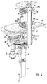
- Fig. 4 shows the drive mechanism according to the invention for the workstations 5 as well as for the turntable 4. Shown is the engine 11 and the downstream of him Transmission 12. About this a drive gear 17 is driven, the meshes with an intermediate gear 18. This intermediate gear 18 in turn meshes with a gear or sprocket 19, attached to a hollow drive shaft 20 is arranged.
- This hollow drive shaft extends from the transmission housing 14, where the described gear connection is arranged by a central opening in the turntable 4 and the mounting plate 15 into the upper device area, where it is stored accordingly.
- On the drive shaft 15 are in the area above the mounting plate 15 two guide means 21a and 21b provided in the form of guide rings 22a, 22b, fixed to the drive shaft 20 are connected.
- Coupling elements 23a, 23b to provide, both as annular or disc-shaped Lifting plate 24a, 24b are formed.
- guide projections 25a and 25b provided project radially outward and a curve or waveform describe.
- On these guide projections 25a, 25b run top and bottom Running or sliding elements 26 in the form of two rollers or rollers, as shown in FIG. 4.
- These running or sliding elements are in appropriate receptacles 27 am Inner circumference of a respective lifting plate 24a, 24b arranged. At least one The rollers or rollers are arranged vertically movable to the entire facial expressions to bring in exact contact with the respective guide projection.
- This respective vertical movement is in a corresponding horizontal movement of a working element of the workstation 5 (via the driver 29) or a vertical movement of a working element the workstation 5 (via the driver 30) converted.
- the motion coupling between the Hubtellern and the respective drivers is off Figs. 5 and 6 can be seen, wherein Fig. 5 shows the two lifting plates, while in Fig. 6, the upper lifting plate is omitted.
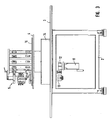
- the two figures also show that a top plate 32 is provided on the upper side, at which the workstation is additionally supported by a suitable fastening device 33.
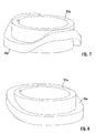
- FIGS. 7 and 8 show the two guide rings 22a, 22b.
- the guide ring 22a and its guide projection 25a respectively responsible for the horizontal stroke.
- the lifting plate 24a once runs between a lowermost and a topmost one Position back and forth. This is a unique during a shaft rotation Horizontal movement of a working element of the workstation 5 to the outside and controlled inwards.
- the guide projection 25b of the guide ring 22b which for the vertical stroke is responsible, two complete curves, that is, the lifting plate 24b runs twice between a lowermost one during a shaft rotation and a supreme position back and forth. This causes the work item controlled via the driver 30 two vertical movements during a shaft rotation performs.
- the driver 30 two vertical movements during a shaft rotation performs.
- the driver engages 37 in a correspondingly positioned recess 38 at a likewise in the transmission housing 14 arranged index plate 39, which in turn via one of the Drive shaft 20 penetrated tubular connection 40 coupled to the turntable 4 is.
- the index plate 39 by an angle increment rotated about the central axis of rotation and with it the turntable 4 to an angular increment corresponding to the clock, that is, the respective one Workpiece carriers are conveyed from one workstation to the next. Is the corresponding index disc position reached and leaves the driver 37, the respective index disk groove 38, attacks a locking means 41 the index plate 39, this in their position until the next adjustment locked.
- the device according to the invention comprises a novel, standardizable Base frame, as shown in the figures, its drive mechanism is designed much easier, and beyond sufficient recording space for all control devices. Overall, such an in Closed device to be created that no external additional Equipment such as control cabinet etc. required.
- On the base frame following the module idea of the device, depending on the workpiece to be produced or parts to be installed according to designed feeders such Also workstations and workpiece carriers are arranged detachably. This means, it is a simple conversion of the described base frame using according to differently designed feeders, workpiece carriers and Workstations conceivable to make a new object. Basically Structure of the base frame is nothing to change here.
Landscapes
- Engineering & Computer Science (AREA)
- Mechanical Engineering (AREA)
- Automatic Assembly (AREA)
- Specific Conveyance Elements (AREA)
- Pens And Brushes (AREA)
- Transmission Devices (AREA)
Abstract
Description
Die Erfindung betrifft eine Fertigungs- und/oder Montagevorrichtung zum Fertigen und/oder Montieren eines Werkstücks, mit einem Vorrichtungsgestell und einem mehrere Werkstückträger aufweisenden, bezüglich einer oder mehrerer feststehender Arbeitsstationen rotierend und getaktet bewegbaren Werkstückträgertisch, sowie mit einem Antriebsmechanismus zum Antreiben der einen oder mehreren Arbeitsstationen, welcher Antriebsmechanismus einen Motor und wenigstens ein mit dem Motor indirekt bewegungsgekoppeltes, im Wesentlichen vertikal bewegbares Kupplungselement, mit dem ein Mitnehmer einer Antriebsstation gekoppelt oder koppelbar ist, aufweist.The invention relates to a manufacturing and / or assembly device for manufacturing and / or mounting a workpiece, with a device frame and a having a plurality of workpiece carriers, with respect to one or more fixed Workstations rotating and clocked movable workpiece carrier table, and a drive mechanism for driving the one or more Workstations, which drive mechanism is a motor and at least one with the motor indirectly motion-coupled, substantially vertically movable Coupling element to which a driver of a drive station coupled or couplable.
Eine solche Fertigungs- und/oder Montagevorrichtung ist beispielsweise aus DE 197 49 633 A1 bekannt. Es handelt sich um einen Rundtaktautomaten mit einem Werkstückträgertisch, auch Drehteller genannt, an dem die Werkstückträger um eine zentrale Vorrichtungsachse getaktet bezüglich oberhalb davon angeordneter Arbeitsstationen, die unterschiedliche Aufgaben erfüllen können, bewegt werden. Eine solche Vorrichtung kommt überall dort zum Einsatz, wo maschinell in mehreren Fertigungs- oder Montagestufen ein Gegenstand herzustellen ist, beispielsweise bei der Herstellung elektrotechnischer oder elektromechanischer Bauteile, feinmechanischer Werkstücke oder auch im pharmazeutischen Bereich wie auch in der Automobilindustrie. Mit einer solchen Vorrichtung ist es möglich, das Werkstück kontinuierlich Stück für Stück zusammenzusetzen oder herzustellen, wozu es getaktet zu den jeweiligen Arbeitsstationen gebracht wird, die Einzelteile des Werkstücks, die über vorrichtungsseitig ebenfalls vorgesehene Zubringeinrichtungen herangefördert werden, greifen und verbauen können oder sonstige Tätigkeiten bezüglich des Werkstücks durchführen können. Als Arbeitsstationen können beispielsweise Handlingeinrichtungen in Form von Zangen und Greifern zum Einsatz kommen, gleichermaßen sind aber auch Schraub-, Schweiß- oder Löteinrichtungen wie auch Präge- oder Druckeinrichtungen einsetzbar. Bei einer Zubringeinrichtung kann es sich beispielsweise um eine Bauteilfördereinrichtung handeln, gleichermaßen auch um eine Stapeleinheit oder ein Stanzband mit einer entsprechenden Stanzeinrichtung, um aus einem Bauteilband die erforderlichen Komponenten herauszustanzen, welche anschließend mit der Arbeitsstation zu verarbeiten sind.Such a manufacturing and / or mounting device is, for example, DE 197 49 633 A1 known. It is a rotary indexing machine with a Workpiece carrier table, also called turntable on which the workpiece carrier um a central device axis clocked with respect to above it Workstations that can perform different tasks are moved. Such a device is used wherever machine in several Manufacturing or assembly stages to produce an object, for example in the manufacture of electrotechnical or electromechanical components, fine mechanical workpieces or in the pharmaceutical sector as well in the automotive industry. With such a device, it is possible to work the workpiece continuously assembled piece by piece or produce, including it is clocked to the respective workstations brought the items of the Workpiece, the device-side also provided Zubringeinrichtungen be promoted, grab and obstruct or other activities with respect to the workpiece. As workstations can For example, handling devices in the form of pliers and grippers are used come, but are equally screw, welding or soldering as well as embossing or printing devices used. At a feeder it may be, for example, a component conveyor act, equally to a stacking unit or a punching tape with a corresponding punching device to the required from a component tape To punch out components, which are then connected to the workstation are process.
Der Antrieb der Arbeitsstationen erfolgt über einen speziellen, hierfür vorgesehenen Antriebsmechanismus, der sicherstellt, dass die Arbeitsstationen zeitgenau die jeweils erforderliche Funktion durchführen. Dies erfolgt in der Regel mechanisch gesteuert. Zentrales Antriebselement ist ein Motor, der indirekt mit einem oder zwei im oberen Bereich, also im Bereich der Arbeitsstationen vorgesehenen Kupplungselementen bewegungsgekoppelt ist. Mit diesen Kupplungselementen ist wiederum ein Mitnehmer, in der Regel in Form eines Arbeitshebels einer Arbeitsstation gekoppelt: Über den Motor und den Antriebsmechanismus ist es nun möglich, das oder die Kupplungselemente vertikal zu bewegen, was zu einer entsprechenden Mitnehmer- oder Arbeitshebelbewegung der Arbeitsstation führt, die dann die entsprechend zugeordnete Vertikal- oder Horizontalbewegung durchführt.The drive of the workstations takes place via a special, provided for this purpose Drive mechanism that ensures that the workstations timely perform the required function. This is usually done mechanically controlled. Central drive element is an engine that indirectly with a or two in the upper area, ie in the area of the workstations Coupling elements is motion coupled. With these coupling elements is again a driver, usually in the form of a working lever of a workstation coupled: it is now possible via the engine and the drive mechanism to move the one or more coupling elements vertically, resulting in a corresponding Driver or work lever movement of the workstation leads then performs the corresponding associated vertical or horizontal movement.
Ein bekannter Antriebsmechanismus, wie er beispielsweise aus DE 197 28 264 A1 bekannt ist, umfasst den Motor, der über ein nachgeschaltetes Winkelgetriebe zwei Kurvenscheiben antreibt, die um eine horizontale Achse drehen. Diese sind wiederum mit zwei vertikal angeordneten Hubstangen verbunden, die die Vorrichtung vertikal durchsetzen, und an deren oberem Ende die ring- oder scheibenartigen Kupplungselemente angeordnet sind, mit denen die Mitnehmer der Arbeitsstationen gekoppelt sind. Bei einer Rotation der Kurvenscheiben werden die Hubstangen entsprechend der Scheibenform vertikal bewegt, und mit ihnen die Kupplungselemente, über die die Bewegung der Arbeitsstationen letztlich gesteuert wird.A known drive mechanism, as for example from DE 197 28 264 A1 is known, includes the engine, which has a downstream angle gear drives two cams that rotate about a horizontal axis. These are in turn connected to two vertically arranged lifting rods connecting the device vertically enforce, and at the upper end of the ring or disc-like Coupling elements are arranged, with which the drivers of the workstations are coupled. During a rotation of the cam disks are the Lifting rods according to the disc shape moved vertically, and with them the Clutch elements over which ultimately controlled the movement of the workstations becomes.
Bei der aus DE 197 28 264 bekannten Vorrichtung sind die zentralen Elemente des Antriebsmechanismus, nämlich der Motor, das Winkelgetriebe sowie die Kurvenscheiben im Vorrichtungsgestell unterhalb des Aufbautellers, auf dem die Zuführeinrichtungen angeordnet sind, positioniert. Das heißt, der gesamte untere Bereich des Vorrichtungsgestells ist mit dem Antriebsmechanismus belegt. Neben dem Umstand, dass ein solcher Antrieb sehr komplex und aufwendig ausgelegt ist, besteht ferner die Notwendigkeit, einen separaten Steuerschrank vorzusehen, in dem die Vorrichtungssteuerung untergebracht ist, nachdem vorrichtungsseitig kein Raum hierfür mehr gegeben ist.In the device known from DE 197 28 264, the central elements the drive mechanism, namely the motor, the angle gear and the cams in the device rack below the mounting plate on which the feeders are positioned. That is, the entire lower one Area of the device rack is occupied by the drive mechanism. Next the fact that such a drive designed very complex and expensive Furthermore, there is a need to provide a separate control cabinet, in which the device controller is housed after the device side there is no room left for this.
Der Erfindung liegt damit das Problem zugrunde, eine Vorrichtung anzugeben, die diesbezüglich verbessert ist.The invention is therefore based on the problem to provide a device which improved in this regard.
Zur Lösung dieses Problems ist bei einer Fertigungs- und/oder Montagevorrichtung der eingangs genannten Art erfindungsgemäß vorgesehen, dass der Antriebsmechanismus eine über den Motor rotierend antreibbare, vertikal angeordnete Antriebswelle mit einer Führungseinrichtung, mit der das Kupplungselement bewegungsgekoppelt ist und über die die Vertikalbewegung des Kupplungselements gesteuert wird, aufweist.To solve this problem is in a manufacturing and / or assembly device of the aforementioned type according to the invention provided that the drive mechanism a rotatably driven via the motor, vertically arranged Drive shaft with a guide device, with the coupling element is motion coupled and via the vertical movement of the coupling element is controlled.
Die erfindungsgemäße Vorrichtung schlägt ein völlig neues Antriebskonzept vor, bei dem im Bereich unterhalb des Aufbautellers, also im unteren Bereich des Vorrichtungsgestells lediglich der Motor und ein ihm nachgeschaltetes Getriebe positioniert ist. Die der Vertikalführung des oder der Kupplungselemente dienenden Komponenten sind sämtlich nach oben verlagert, sie befinde sich also nicht mehr wie im Stand der Technik im unteren Bereich des Vorrichtungsgestells. Der Antrieb erfolgt über eine rotierende, zentrale vertikale Antriebswelle, an der eine Führungseinrichtung vorgesehen ist, die bei einer Wellenrotation gleichermaßen rotiert, und mit der ein Kupplungselement bewegungsgekoppelt ist. Die Führungseinrichtung ist derart ausgelegt, dass die gewünschte Vertikalbewegung des Kupplungselements entsprechend gesteuert wird.The device according to the invention proposes a completely new drive concept, in the area below the mounting plate, ie in the lower region of the device frame only the engine and a downstream transmission positioned is. The serving the vertical guide of the coupling or the elements Components are all shifted upwards, so they are not anymore as in the prior art at the bottom of the device frame. The drive via a rotating, central vertical drive shaft, on which a guide device is provided which rotates in a wave rotation equally, and with which a coupling element is motion coupled. The management device is designed such that the desired vertical movement of the Clutch element is controlled accordingly.
Der bei der erfindungsgemäßen Vorrichtung konzipierte Antriebsmechanismus ist gegenüber dem bisher bekannten Kurvenscheiben- und Hubstangenmechanismus wesentlich einfacher ausgestaltet. Dies führt weiterhin zu einer deutlichen Reduzierung der Herstellungskosten. Ein weiterer bemerkenswerter Vorteil ist, dass im unteren Bereich der Vorrichtung, also unterhalb der Aufbauplatte keinerlei weitere Antriebskomponenten außer dem Motor und dem relativ kleinformatig dimensionierten Getriebe vorzusehen sind. Dieser Raum kann mit besonderem Vorteil zur Integration der Steuerungseinrichtung genutzt werden, so dass auch der im Stand der Technik stets erforderliche separate Steuerschrank entfällt. Insgesamt wird auf Basis des erfindungsgemäßen Antriebsmechanismus eine wesentliche Vorrichtungsvereinfachung realisiert, wobei mit der erfindungsgemäßen Vorrichtung jedoch gleichermaßen hinsichtlich der Anzahl der Antriebsstationen auslegbare Vorrichtungen in der aus DE 197 49 633 A1 bekannten Modulbauweise in einem standardisierten Grundgestell konzipiert werden können.The drive mechanism designed in the device according to the invention is compared to the previously known cam and Hubstangenmechanismus designed much simpler. This continues to lead to a significant reduction the production costs. Another notable advantage is that in the bottom of the device, so below the mounting plate no further Drive components except the engine and the relatively small sized To provide transmission. This room can be used with particular advantage Integration of the control device can be used, so that even in the state the technology always required separate control cabinet deleted. Overall, it will open Basis of the drive mechanism according to the invention a substantial device simplification realized, but with the inventive device equally interpretable with regard to the number of drive stations devices in the known from DE 197 49 633 A1 modular design in one standardized base frame can be designed.
Wie bereits beschrieben besteht die Möglichkeit, an der vertikalen Antriebswelle eine Führungseinrichtung anzuordnen, die für eine Horizontal- oder Vertikalbewegung der Arbeitsstation bzw. ihres Arbeitsgeräts je nach Auslegung sorgt. Selbstverständlich besteht auch die Möglichkeit, zwei separate, übereinander angeordnete Führungseinrichtungen vorzusehen, mit denen jeweils ein Kupplungselement, mit denen jeweils ein Mitnehmer einer Arbeitsstation gekoppelt oder koppelbar ist, bewegungsgekoppelt ist. In diesem Fall wäre ein Kupplungselement für die Vertikal- und das andere für die Horizontalbewegung der Antriebsstation vorgesehen.As already described, there is the possibility of the vertical drive shaft to arrange a guide device for a horizontal or vertical movement the workstation or its implement depending on the design ensures. Of course There is also the possibility of two separate, one above the other To provide guide devices, each with a coupling element, with each of which a driver of a workstation is coupled or can be coupled, is motion coupled. In this case, a coupling element for the vertical and the other is provided for the horizontal movement of the drive station.
Nach einer ersten Erfindungsausgestaltung kann eine Führungseinrichtung als nach außen ragender, umlaufender Führungsvorsprung ausgebildet sein, auf dem ein oder mehrere am Kupplungselement vorgesehene Lauf- oder Gleitelemente laufen, die zweckmäßigerweise als Rollen oder Walzen ausgebildet sein können. Der Führungsvorsprung läuft um die Antriebswelle herum und beschreibt eine Kurven- oder Wellenform, der das Kupplungselement aufgrund seiner Kopplung über die Rollen oder Walzen folgt und entsprechend der Kurvenform vertikal bewegt wird. Zweckmäßigerweise sind dabei zwei Lauf- oder Gleitelemente, insbesondere zwei Rollen oder Walzen einander gegenüberstehend angeordnet, das Paar nimmt also den Führungsvorsprung zwischen sich auf. Zur Anpassung ist es zweckmäßig, wenn das oder zumindest ein Teil der Lauf- oder Gleitelemente, insbesondere der Rollen oder der Walzen vertikal verstellbar ist.According to a first embodiment of the invention, a guide device can be described as be formed outwardly projecting, circumferential guide projection, on the one or more provided on the coupling element running or sliding elements run, which can be suitably designed as rollers or rollers. The guide projection runs around the drive shaft and describes a Curve or waveform that the coupling element due to its coupling follows over the rollers or rollers and moves vertically according to the curve shape becomes. Appropriately, there are two running or sliding elements, in particular two rollers or rollers arranged opposite each other, the So couple picks up the leadership lead between them. To adapt it is expedient if that or at least part of the running or sliding elements, in particular the rollers or the rollers is vertically adjustable.
Alternativ zur Auslegung der Führungseinrichtung mit einem nach außen vorspringenden Führungsvorsprung besteht die Möglichkeit, dass die Führungseinrichtung als umlaufende Nut ausgebildet ist, in die eine oder mehrere am Kupplungselement vorgesehene Lauf- oder Gleitelemente, in diesem Fall zweckmäßigerweise als im Wesentlichen horizontal vorspringende Zapfen ausgebildet, eingreifen. Auch in diesem Fall beschreibt die Führungsnut, die um die Antriebsachse umläuft, eine entsprechende Kurven- oder Wellenform, die die Vertikalbewegung steuert, und der das Kupplungselement entsprechend folgt.Alternatively to the design of the guide device with an outwardly projecting Leadership advantage is the possibility that the management facility is designed as a circumferential groove, in which one or more on the coupling element provided running or sliding elements, in this case expediently formed as a substantially horizontally protruding pin, engage. Also in this case describes the guide groove, which rotates about the drive axis, a corresponding curve or waveform representing the vertical movement controls, and follows the coupling element accordingly.
Eine zweckmäßige Erfindungsausgestaltung sieht vor, den Führungsvorsprung oder die Führungsnut an einem an der Antriebswelle angeordneten Ring auszubilden. Dieser Ring, der entsprechend separat gefertigt werden kann, wird in geeigneter Weise an der Antriebswelle befestigt. Sind zwei Führungseinrichtungen vorgesehen, sind selbstverständlich zwei entsprechende Ringe wellenseitig angeordnet.An expedient embodiment of the invention provides for the guiding projection or form the guide groove on a arranged on the drive shaft ring. This ring, which can be made separately, will be suitable Way attached to the drive shaft. Are two management facilities provided, Of course, two corresponding rings are arranged on the shaft side.
Wie beschrieben erfolgt die Steuerung der Vertikalbewegung der Kupplungselemente dadurch, dass die Lauf- oder Gleitelemente von dem Führungsvorsprung oder der Führungsnut geführt werden. Um eine möglichst reibungsfreie Bewegung zu realisieren, besteht die Möglichkeit, dass das oder die Lauf- oder Gleitelemente eine einen geringen Reibungswiderstand aufweisende Beschichtung aufweisen oder aus einem solchen Material sind. Selbstverständlich können sie auch von Haus aus aus Metall sein, solange ein möglichst reibungsfreier Lauf gewährleistet ist.As described, the control of the vertical movement of the coupling elements takes place in that the running or sliding elements of the guide projection or the guide groove are guided. To move as smoothly as possible To realize, there is the possibility that the one or more running or sliding elements have a low frictional resistance coating or of such a material. Of course you can also from House made of metal, as long as possible ensures a smooth running is.
Der Motor selbst treibt erfindungsgemäß ein Antriebszahnrad vorzugsweise über ein zwischengeschaltetes Getriebe an, welches direkt oder indirekt mit einem an der vertikalen Antriebswelle vorgesehenen Zahnrad oder Zahnkranz zusammenwirkt und die Welle antreibt.The motor itself drives according to the invention preferably via a drive gear an intermediate gear, which directly or indirectly with an on the vertical drive shaft provided gear or ring gear cooperates and the shaft is driving.
Dem Motor kommt bei der erfindungsgemäßen Anlage aber nicht nur die Funktion zu, die Antriebswelle und damit die Kupplungselemente anzutreiben, er hat vielmehr ferner auch die Funktion, für den Antrieb des Drehtellers, an dem die Werkstückträger angeordnet sind, zu sorgen. Zu diesem Zweck ist erfindungsgemäß über den Motor eine Treiberscheibe rotierend antreibbar, die einen Mitnehmer aufweist, der zum getakteten Bewegen des Werkstückträgers mit einer diesem zugeordneten Indexscheibe zusammenwirkt, die wiederum mit dem Drehteller verbunden ist. Um auf einfache Weise für einen gemeinsamen Antrieb sowohl der Treiberscheibe wie auch der Antriebswelle zu sorgen, ist es zweckmäßig, wenn das über den Motor angetriebene Antriebszahnrad über ein Zwischenzahnrad mit dem wellenseitigen Zahnrad oder Zahnkranz zusammenwirkt, und wenn ein mit dem Zwischenzahnrad um dieselbe Achse drehbares weiteres Zahnrad vorgesehen ist, das mit einem an der Treiberscheibe vorgesehen Zahnrad zusammenwirkt. Zweckmäßigerweise sind das weitere Zahnrad und das treiberscheibenseitige Zahnrad als Ellipsenzahnräder ausgeführt. Zur Ermöglichung einer Änderung des Arbeitstaktes ist es ferner möglich, das über den Motor angetriebene Antriebszahnrad und das Zwischenzahnrad, die beide lösbar sind, gegeneinander auszutauschen. Aufgrund der unterschiedlichen Übersetzungsverhältnisse bzw. Zahnradauslegung ergibt sich folglich eine Antriebs- und Taktänderung, die ausgenutzt werden kann.The engine comes in the system according to the invention but not only the function to drive the drive shaft and thus the coupling elements, he has rather Furthermore, the function for the drive of the turntable on which the workpiece carrier are arranged to provide. For this purpose is according to the invention via the engine a drive disc driven in rotation, the one driver having, for clocked moving the workpiece carrier with a this associated index disc interacts, in turn, with the turntable connected is. In a simple way for a common drive both the Driver disk as well as the drive shaft to provide, it is useful if the drive gear driven by the motor via an intermediate gear with the shaft side gear or ring gear cooperates, and if with a the intermediate gear rotatable about the same axis further provided gear is that cooperates with a gear provided on the driving wheel. Conveniently, the other gear and the drive pulley side Gear designed as Ellipsenzahnräder. To enable a change the power stroke, it is also possible, driven via the motor drive gear and the idler gear, both of which are releasable, against each other exchange. Due to the different transmission ratios or Gear design thus results in a drive and clock change, which exploited can be.
Besonders zweckmäßig ist es, wenn die Antriebswelle eine Hohlwelle ist. Diese ermöglicht es, durch die Hohlwelle die Versorgungs- und/oder Steuerleitungen von einer im Vorrichtungsgestell unterhalb des bereits beschriebenen Aufbautisches angeordneten Steuerungseinrichtung zu den Antriebsstationen oder anderen Verbrauchern im oberen Vorrichtungsbereich zu führen.It is particularly expedient if the drive shaft is a hollow shaft. These makes it possible, through the hollow shaft, the supply and / or control lines of one in the device frame below the construction table already described arranged control device to the drive stations or others Consumers in the upper device area.
Weitere Vorteile, Merkmale und Einzelheiten der Erfindung ergeben sich aus dem im folgenden beschriebenen Ausführungsbeispiel sowie anhand der Zeichnungen. Dabei zeigen:
- Fig. 1
- eine Perspektivansicht einer erfindungsgemäßen Fertigungs- und/oder Montagevorrichtung,
- Fig. 2
- eine Perspektivansicht des Vorrichtungsgestells mit dem Arbeitsaufbau,
- Fig. 3
- eine Seitenansicht der Darstellung aus Fig. 2,
- Fig. 4
- eine Detaildarstellung des Antriebsmechanismus für die Kupplungselemente sowie des Drehtellers,
- Fig. 5
- eine Detaildarstellung der Vorrichtung im Bereich der Antriebsstationen,
- Fig. 6
- die Ansicht aus Fig. 5 mit lediglich einem Kupplungselement,
- Fig. 7
- ein Führungsring mit einem Führungsvorsprung für den Vertikalhub, und
- Fig. 8
- ein Führungsring mit einem Führungsvorsprung für den Horizontalhub.
- Fig. 1
- a perspective view of a manufacturing and / or assembly device according to the invention,
- Fig. 2
- a perspective view of the device frame with the working structure,
- Fig. 3
- a side view of the illustration of FIG. 2,
- Fig. 4
- a detailed view of the drive mechanism for the coupling elements and the turntable,
- Fig. 5
- a detailed representation of the device in the area of the drive stations,
- Fig. 6
- the view from FIG. 5 with only one coupling element,
- Fig. 7
- a guide ring with a guide projection for the vertical stroke, and
- Fig. 8
- a guide ring with a guide projection for the horizontal stroke.
Fig. 1 zeigt eine erfindungsgemäße Fertigungs- und/oder Montagevorrichtung 1.
Diese umfasst, siehe Fig. 2, ein Vorrichtungsgestell 2, auf dem oberseitig eine
Aufbauplatte 3 angeordnet ist, auf der entsprechende, nicht näher gezeigte Zuführeinrichtungen
angeordnet werden können. Die lokale Positionierung wie auch
die Anzahl der anordbaren Zubringeinrichtungen hängt vom Bohrbild der Befestigungslöcher
der Aufbauplatte 3 ab. Vorgesehen ist ferner ein Werkstückträgertisch
4 in Form eines Drehtellers, an dem ebenfalls nicht näher gezeigte Werkstückträger
in geeigneten Aufnahmen befestigt werden können. Dieser Drehteller
4 kann, wie nachfolgend noch beschrieben wird, getaktet bezüglich feststehend
angeordneter Arbeitsstationen 5, von denen eine in den Fig. 1 und 2 gezeigt ist,
bewegt werden. Diese Arbeitsstationen dienen beispielsweise zum Entnehmen
eines von einer Zubringeinrichtung angeförderten Kleinteils und zum Verbauen
desselben am Werkstück im Werkstückträger, der sich im Arbeitsbereich der Arbeitsstation
5 befindet.1 shows a production and / or assembly device 1 according to the invention.
This includes, see Fig. 2, a
Im unteren Bereich ist das Vorrichtungsgestell über entsprechende Platten oder
Scheiben 6, die zum Teil lösbar sind, um das Vorrichtungsinnere zu gelangen,
geschlossen. Auch der daran anschließende Bereich, in dem die Zubringeinrichtungen
befestigt werden können, ist zumindest solange, als keine vorgesehen
sind, über geeignete Platten oder Scheiben 7 geschlossen. Ferner ist der obere
Bereich, in dem die Bewegung etwaiger beweglicher Teile der Zubringeinrichtungen
und insbesondere der Arbeitsstationen erfolgt, über im gezeigten Beispiel gebogenen
Scheiben 8 komplett geschlossen. Um in das Innere zu gelangen, ist es
möglich, eine Scheibe 8'etwas nach außen zu bewegen und geführt über eine benachbarte
Scheibe zu schieben. Gezeigt ist ferner der Horizontalträger 9, an dem
eine Aufnahme 10 für eine nicht näher gezeigte Bedieneinrichtung vorgesehen ist.In the lower part of the device frame is on appropriate plates or
Fig. 2 und Fig. 3 zeigen die Vorrichtung aus Fig. 1 ohne die Gehäuseteile. Gezeigt
ist ein im Inneren des Vorrichtungsgestells 2 unterhalb der Aufbauplatte 3 angeordneter
Motor 11, dem die zentrale Antriebsfunktion sowohl der Arbeitsstationen
5 als auch des Drehtellers 4 zukommt. Im Bereich unterhalb des Aufbautellers 3
befindet sich ferner noch das dem Motor nachgeschaltete Getriebe 12 sowie eine
Überlastkupplung 13, worauf nachfolgend noch eingegangen wird. Oberhalb des
Aufbautellers 3 befindet sich das Getriebegehäuse 14, in dem die Bewegungskopplung
zwischen Motor 11 bzw. Getriebe 12 und nachgeschalteten Antriebskomponenten
erfolgt. Dem Getriebegehäuse 14 nachgeschaltet ist der Drehteller 4
sowie die feststehende Aufbauplatte 15, auf der wie beschrieben die Arbeitsstationen
5 gemäß dem dortigen Bohrbild positioniert werden können. Diese greifen
über noch zu beschreibende Mitnehmer in Form von Hebelarmen an entsprechenden
Kupplungselementen in Form von scheiben- oder ringartigen Hubtellern
an, die hinter geeigneten Verkleidungsteilen 16 angeordnet sind.Fig. 2 and Fig. 3 show the device of Fig. 1 without the housing parts. Shown
is a disposed inside the
Wie insbesondere Fig. 3 zeigt, befindet sich bei der erfindungsgemäßen Vorrichtung
im Bereich des Vorrichtungsgestells 2 lediglich der Motor 11, das Getriebe 12
sowie die Überlastkupplung 13. Ansonsten steht der gesamte Bereich zur Integration
der Steuerungseinrichtung der Vorrichtung zur Verfügung.As particularly shown in FIG. 3, located in the device according to the invention
in the region of the
Fig. 4 zeigt den erfindungsgemäßen Antriebsmechanismus für die Arbeitsstationen
5 wie auch für den Drehteller 4. Gezeigt ist der Motor 11 und das ihm nachgeschaltete
Getriebe 12. Über dieses wird ein Antriebszahnrad 17 angetrieben, das
mit einem Zwischenzahnrad 18 kämmt. Dieses Zwischenzahnrad 18 seinerseits
kämmt mit einem Zahnrad oder Zahnkranz 19, der an einer hohlen Antriebswelle
20 angeordnet ist. Diese hohle Antriebswelle erstreckt sich aus dem Getriebegehäuse
14, wo die beschriebene Zahnradverbindung angeordnet ist, durch eine
zentrale Öffnung im Drehteller 4 und der Aufbauplatte 15 bis in den oberen Vorrichtungsbereich,
wo sie entsprechend gelagert ist. An der Antriebswelle 15 sind
im Bereich oberhalb der Aufbauplatte 15 zwei Führungseinrichtungen 21a und 21b
in Form von Führungsringen 22a, 22b vorgesehen, die fest mit der Antriebswelle
20 verbunden sind. Diese Führungsringe 22a, 22b, auf die nachfolgend noch eingegangen
wird, haben die Aufgabe, für eine Vertikalführung von mit ihnen gekoppelten
Kupplungselementen 23a, 23b zu sorgen, die beide als ring- oder scheibenförmige
Hubteller 24a, 24b ausgebildet sind. Zu diesem Zweck sind, siehe die
Fig. 7 und 8, an den Führungsringen 22a, 22b Führungsvorsprünge 25a bzw. 25b
vorgesehen, die radial nach außen vorspringen und eine Kurven- oder Wellenform
beschreiben. Auf diesen Führungsvorsprüngen 25a, 25b laufen ober- und unterseitig
Lauf- oder Gleitelemente 26 in Form zweier Rollen oder Walzen, wie in Fig.
4 gezeigt. Diese Lauf- oder Gleitelemente sind in geeigneten Aufnahmen 27 am
Innenumfang eines jeweiligen Hubtellers 24a, 24b angeordnet. Wenigstens eine
der Rollen oder Walzen ist vertikal bewegbar angeordnet, um die gesamte Mimik
in exakte Anlage an den jeweiligen Führungsvorsprung zu bringen.Fig. 4 shows the drive mechanism according to the invention for the
Wird nun der Motor 11 angetrieben, so erfolgt hierüber ein indirekter Antrieb der
Antriebswelle 20. Bei einer Rotation der Antriebswelle 20 drehen auch die beiden
Führungsringe 22a, 22b und mit ihnen die jeweiligen Führungsvorsprünge 25a,
25b. Aufgrund ihrer Kurvenform werden nun, der Form folgend, infolge des Rollenoder
Walzenabgriffs auch die beiden Hubteller 24a, 24b, die an geeigneten Vertikalführungen
28 angeordnet sind, vertikal bewegt. Diese Vertikalbewegung wird
auf Mitnehmer 29, 30 einer Arbeitsstation 5 übertragen, welche Mitnehmer 29 und
30 als Arbeitshebel ausgebildet sind. Diese greifen mit ihren inwärtigen Enden in
eine Kupplungsnut 31a bzw. 31b des jeweiligen Hubtellers 24a, 24b. Bei einer
Vertikalbewegung des jeweiligen Hubtellers 24a, 24b werden also auch die entsprechenden
Mitnehmer 29, 30 vertikal bewegt. Diese jeweilige Vertikalbewegung
wird in eine entsprechende Horizontalbewegung eines Arbeitselements der Arbeitsstation
5 (über den Mitnehmer 29) bzw. eine Vertikalbewegung eines Arbeitselements
der Arbeitsstation 5 (über den Mitnehmer 30) gewandelt. Die Bewegungskopplung
zwischen den Hubtellern und den jeweiligen Mitnehmern ist aus
den Fig. 5 und 6 ersichtlich, wobei Fig. 5 die beiden Hubteller zeigt, während in
Fig. 6 der obere Hubteller weggelassen ist. Die beiden Figuren zeigen weiterhin,
dass oberseitig eine Abschlussplatte 32 vorgesehen ist, an der die Arbeitsstation
über eine geeignete Befestigungseinrichtung 33 zusätzlich gehaltert ist.Now, if the
Wie bereits beschrieben zeigen die Fig. 7 und 8 die beiden Führungsringe 22a,
22b. Wie beschrieben ist der Führungsring 22a bzw. sein Führungsvorsprung 25a
für den Horizontalhub verantwortlich. Während einer Rotation des Führungsringes
22a läuft der Hubteller 24a einmal zwischen einer untersten und einer obersten
Stellung hin und her. Hierüber wird während einer Wellenumdrehung eine einmalige
Horizontalbewegung eines Arbeitselements der Arbeitsstation 5 nach außen
und nach innen gesteuert.As already described, FIGS. 7 and 8 show the two
Demgegenüber zeigt der Führungsvorsprung 25b des Führungsrings 22b, der für
den Vertikalhub verantwortlich ist, zwei vollständige Kurven, das heißt, der Hubteller
24b läuft während einer Wellenumdrehung zweimal zwischen einer untersten
und einer obersten Stellung hin und her. Dies führt dazu, dass das Arbeitselement
über den Mitnehmer 30 gesteuert zwei Vertikalbewegungen während einer Wellenumdrehung
durchführt. Selbstverständlich ist es je nach Ausgestaltung der Vorrichtung
bzw. Arbeitsstation denkbar, auch andere Kurvenformen vorzusehen.In contrast, the
Wie aus Fig. 4 zu entnehmen ist, erfolgt über den Motor 11 nicht nur der Antrieb
der Antriebswelle 20 und der Hubteller 24a, 24b und damit der Antrieb der Arbeitsstationen
5, sondern auch der Antrieb des Drehtellers 4. Zu diesem Zweck ist
auf dem Zwischenzahnrad 18, um die gleiche Achse drehend, ein weiteres Zahnrad
34 in Form eines Ellipsenzahnrades vorgesehen, das mit einem Zahnrad 35,
das ebenfalls als Ellipsenzahnrad ausgebildet ist, kämmt, mit dem wiederum eine
Treiberscheibe 36 mit einem nach oben vorspringenden Mitnehmer 37 verbunden
ist. Die Treiberscheibe 36 wie auch das Zahnrad 35 sind mit der Überlastkupplung
13 verbunden. Bei Betrieb des Motors 11 dreht nun das Zwischenzahnrad 18 und
mit ihm das weitere Zahnrad 34 und über dieses bewegt das Zahnrad 35 und damit
die Treiberscheibe 36. Während einer solchen Rotation greift der Mitnehmer
37 in eine entsprechend positionierte Ausnehmung 38 an einer ebenfalls im Getriebegehäuse
14 angeordneten Indexscheibe 39, die ihrerseits über eine von der
Antriebswelle 20 durchsetzte rohrartige Verbindung 40 mit dem Drehteller 4 gekoppelt
ist. Über den Mitnehmer 37 wird nun die Indexscheibe 39 um ein Winkelinkrement
um die zentrale Rotationsachse gedreht und mit ihr der Drehteller 4 um
ein dem Takt entsprechendes Winkelinkrement weiterbewegt, das heißt, die jeweiligen
Werkstückträger werden von einer Arbeitsstation zur jeweils nächsten gefördert.
Ist die entsprechende Indexscheibenstellung erreicht und verlässt der Mitnehmer
37 die jeweilige Indexscheibennut 38, greift ein Arretierungsmittel 41 an
der Indexscheibe 39 an, das diese in ihrer Position bis zur nächsten Verstellung
arretiert.As can be seen from FIG. 4, not only the drive takes place via the
Die erfindungsgemäße Vorrichtung umfasst ein neuartiges, standardisierbares Grundgestell, wie es in den Figuren dargestellt ist, dessen Antriebsmechanismus wesentlich einfacher konzipiert ist, und das darüber hinaus hinreichenden Aufnahmeraum für sämtliche Steuereinrichtungen bietet. Insgesamt kann so eine in sich geschlossene Vorrichtung geschaffen werden, die keinerlei externe zusätzliche Gerätschaften wie Steuerschrank etc. benötigt. An dem Grundgestell können, dem Modulgedanken der Vorrichtung folgend, je nach herzustellendem Werkstück bzw. zu verbauenden Teilen entsprechend ausgelegte Zuführeinrichtungen wie auch Arbeitsstationen und Werkstückträger lösbar angeordnet werden. Das heißt, es ist eine einfache Umrüstung des beschriebenen Grundgestells unter Verwendung entsprechend anders konzipierter Zuführeinrichtungen, Werkstückträger und Arbeitsstationen denkbar, um einen neuen Gegenstand herzustellen. Am grundsätzlichen Aufbau des Grundgestells ist hierbei nichts zu ändern.The device according to the invention comprises a novel, standardizable Base frame, as shown in the figures, its drive mechanism is designed much easier, and beyond sufficient recording space for all control devices. Overall, such an in Closed device to be created that no external additional Equipment such as control cabinet etc. required. On the base frame, following the module idea of the device, depending on the workpiece to be produced or parts to be installed according to designed feeders such Also workstations and workpiece carriers are arranged detachably. This means, it is a simple conversion of the described base frame using according to differently designed feeders, workpiece carriers and Workstations conceivable to make a new object. Basically Structure of the base frame is nothing to change here.
Claims (16)
Applications Claiming Priority (2)
| Application Number | Priority Date | Filing Date | Title |
|---|---|---|---|
| DE10343978 | 2003-09-19 | ||
| DE10343978A DE10343978B4 (en) | 2003-09-19 | 2003-09-19 | Manufacturing and / or assembly device |
Publications (3)
| Publication Number | Publication Date |
|---|---|
| EP1516699A2 true EP1516699A2 (en) | 2005-03-23 |
| EP1516699A3 EP1516699A3 (en) | 2006-06-07 |
| EP1516699B1 EP1516699B1 (en) | 2008-10-08 |
Family
ID=34177901
Family Applications (1)
| Application Number | Title | Priority Date | Filing Date |
|---|---|---|---|
| EP04022114A Expired - Lifetime EP1516699B1 (en) | 2003-09-19 | 2004-09-17 | Production and/or assembly device |
Country Status (5)
| Country | Link |
|---|---|
| US (1) | US7237328B2 (en) |
| EP (1) | EP1516699B1 (en) |
| AT (1) | ATE410266T1 (en) |
| DE (2) | DE10343978B4 (en) |
| ES (1) | ES2314325T3 (en) |
Cited By (1)
| Publication number | Priority date | Publication date | Assignee | Title |
|---|---|---|---|---|
| ITTV20120041A1 (en) * | 2012-03-19 | 2013-09-20 | Sinteco S P A | WORK STATION FOR INDUSTRIAL AUTOMATION SYSTEMS |
Families Citing this family (11)
| Publication number | Priority date | Publication date | Assignee | Title |
|---|---|---|---|---|
| US9027215B2 (en) * | 2008-02-20 | 2015-05-12 | Hirata Corporation | Production apparatus |
| DE202011003069U1 (en) * | 2011-02-17 | 2011-04-28 | Kadia Produktion Gmbh + Co. | Device for the mechanical surface treatment of workpieces |
| ITBS20110132A1 (en) | 2011-09-28 | 2013-03-29 | Gnutti Transfer S P A | MACHINE TOOL WITH A MAIN BODY WITH A ROLLING TABLE THAT SUPPORTS THE PIECES |
| ITTV20120039A1 (en) * | 2012-03-19 | 2013-09-20 | Sinteco S P A | MANIPULATOR DEVICE FOR INDUSTRIAL AUTOMATION SYSTEMS |
| CN102976123B (en) * | 2012-11-28 | 2015-09-02 | 天津市环欧半导体材料技术有限公司 | A kind of feed mechanism of chamfering device |
| US11161211B1 (en) * | 2018-06-28 | 2021-11-02 | Automated Assembly Corporation | Dual rotary positioning apparatus and method |
| CN111975345B (en) * | 2020-07-23 | 2025-02-14 | 浙江鑫和粉末冶金制品有限公司 | A multi-process gearbox assembly machine |
| CN113941853B (en) * | 2021-11-09 | 2024-12-27 | 太仓敏锐自动化科技有限公司 | A rotating disc device for piston rod assembly |
| CN117206894A (en) * | 2023-09-06 | 2023-12-12 | 上海科文斯集成微电有限公司 | Semiconductor equipment splicing and installation auxiliary equipment |
| DE102023132128A1 (en) * | 2023-11-17 | 2025-05-22 | Technivation AG | rotary indexing table |
| CN117680952B (en) * | 2024-01-31 | 2024-04-16 | 宏耀建设集团有限公司 | Steel structure assembly processing platform |
Family Cites Families (8)
| Publication number | Priority date | Publication date | Assignee | Title |
|---|---|---|---|---|
| US2324523A (en) * | 1941-09-15 | 1943-07-20 | Solar Corp | Machine for assembling storage battery plates and separators |
| US4313260A (en) * | 1979-04-02 | 1982-02-02 | Swanson-Erie Corporation | Assembly machine |
| CH678029A5 (en) | 1990-01-23 | 1991-07-31 | Mikron Sa | |
| DE4212887C1 (en) * | 1992-04-17 | 1993-05-06 | Weiss Gmbh, 6967 Buchen, De | Rotary indexing machine tool - has indexing work-table and several fixed work-stations, also gripper on arm moving workpieces to table |
| DE4302788A1 (en) * | 1993-02-02 | 1994-08-04 | Schumag Ag | Process for translational movement of components and movement drive for carrying out the process |
| DE19749633B4 (en) * | 1997-11-11 | 2005-06-09 | Feintool International Holding | Manufacturing and / or assembly device |
| DE19728264C2 (en) * | 1997-06-26 | 2001-11-29 | Feintool Internat Holding Lyss | Assembly or production machine with work stations |
| WO1998058763A1 (en) * | 1997-06-21 | 1998-12-30 | Siegmund Kumeth | Assembly or manufacturing robot and work station for the same |
-
2003
- 2003-09-19 DE DE10343978A patent/DE10343978B4/en not_active Expired - Fee Related
-
2004
- 2004-09-16 US US10/942,642 patent/US7237328B2/en not_active Expired - Fee Related
- 2004-09-17 DE DE502004008192T patent/DE502004008192D1/en not_active Expired - Lifetime
- 2004-09-17 ES ES04022114T patent/ES2314325T3/en not_active Expired - Lifetime
- 2004-09-17 AT AT04022114T patent/ATE410266T1/en active
- 2004-09-17 EP EP04022114A patent/EP1516699B1/en not_active Expired - Lifetime
Cited By (1)
| Publication number | Priority date | Publication date | Assignee | Title |
|---|---|---|---|---|
| ITTV20120041A1 (en) * | 2012-03-19 | 2013-09-20 | Sinteco S P A | WORK STATION FOR INDUSTRIAL AUTOMATION SYSTEMS |
Also Published As
| Publication number | Publication date |
|---|---|
| ATE410266T1 (en) | 2008-10-15 |
| DE10343978A1 (en) | 2005-04-28 |
| US20050060879A1 (en) | 2005-03-24 |
| EP1516699A3 (en) | 2006-06-07 |
| DE10343978B4 (en) | 2012-03-29 |
| DE502004008192D1 (en) | 2008-11-20 |
| ES2314325T3 (en) | 2009-03-16 |
| EP1516699B1 (en) | 2008-10-08 |
| US7237328B2 (en) | 2007-07-03 |
Similar Documents
| Publication | Publication Date | Title |
|---|---|---|
| EP2208549B1 (en) | Rotation stretch bending tool with eccentric clamp | |
| EP1733155B1 (en) | Actuator | |
| DE10343978B4 (en) | Manufacturing and / or assembly device | |
| EP2542400A1 (en) | Mounting device for a rotatable center part in an injection molding device | |
| DE1956429C3 (en) | Mounting device | |
| EP3602217B1 (en) | Transport device for rotatably and/or linearly moving a workpiece | |
| EP2872288A1 (en) | Rotary table, circular indexing table, assembly system, and operating method | |
| EP2840282B1 (en) | Actuator comprising limit switches | |
| EP2916994B1 (en) | Manufacturing plant for producing an assembly consisting of a plurality of components | |
| DE19727845C2 (en) | Device and method for assembling chains consisting of at least plates and connecting bolts, in particular tooth chains #### | |
| DE102011107467A1 (en) | Rotary transfer machine | |
| DE102008006175B4 (en) | Tool changing device | |
| EP1097657A1 (en) | Telescopic driving unit | |
| DE102010036184B4 (en) | Press | |
| DE19728264C2 (en) | Assembly or production machine with work stations | |
| DE2927823A1 (en) | PLATE MAGAZINE AS A TOOL STORAGE OF A UNIVERSAL DRILLING AND MILLING MACHINE | |
| EP3573791A1 (en) | Separable rotary table | |
| DE202013103426U1 (en) | Device for producing a bore in a workpiece or a thread in a bore of a workpiece | |
| DE3507224A1 (en) | Assembly device | |
| EP4051528B1 (en) | Gearing arrangement for a spindle drive arrangement, spindle drive arrangement, and vehicle seat | |
| DE4111547A1 (en) | Cyclic automated assembly machine - uses single drive motor to operate all functions via worm drive and cams | |
| DE2950674A1 (en) | Turntable for work transfer assembly - is rotated stepwise via maltese cross drive and transmission contg. meshing elliptical gear wheels | |
| DE102013108170B3 (en) | Device for producing a bore in a workpiece or a thread in a bore of a workpiece | |
| DE10257151A1 (en) | Machine tool, especially for cutting, has tool magazine associated with multiple spindles for machining workpieces | |
| DE4435282A1 (en) | Machine for fabrication of metal bent components |
Legal Events
| Date | Code | Title | Description |
|---|---|---|---|
| PUAI | Public reference made under article 153(3) epc to a published international application that has entered the european phase |
Free format text: ORIGINAL CODE: 0009012 |
|
| AK | Designated contracting states |
Kind code of ref document: A2 Designated state(s): AT BE BG CH CY CZ DE DK EE ES FI FR GB GR HU IE IT LI LU MC NL PL PT RO SE SI SK TR |
|
| AX | Request for extension of the european patent |
Extension state: AL HR LT LV MK |
|
| PUAL | Search report despatched |
Free format text: ORIGINAL CODE: 0009013 |
|
| AK | Designated contracting states |
Kind code of ref document: A3 Designated state(s): AT BE BG CH CY CZ DE DK EE ES FI FR GB GR HU IE IT LI LU MC NL PL PT RO SE SI SK TR |
|
| AX | Request for extension of the european patent |
Extension state: AL HR LT LV MK |
|
| 17P | Request for examination filed |
Effective date: 20060715 |
|
| 17Q | First examination report despatched |
Effective date: 20061106 |
|
| AKX | Designation fees paid |
Designated state(s): AT BE BG CH CY CZ DE DK EE ES FI FR GB GR HU IE IT LI LU MC NL PL PT RO SE SI SK TR |
|
| 17Q | First examination report despatched |
Effective date: 20061106 |
|
| GRAP | Despatch of communication of intention to grant a patent |
Free format text: ORIGINAL CODE: EPIDOSNIGR1 |
|
| GRAS | Grant fee paid |
Free format text: ORIGINAL CODE: EPIDOSNIGR3 |
|
| GRAA | (expected) grant |
Free format text: ORIGINAL CODE: 0009210 |
|
| AK | Designated contracting states |
Kind code of ref document: B1 Designated state(s): AT BE BG CH CY CZ DE DK EE ES FI FR GB GR HU IE IT LI LU MC NL PL PT RO SE SI SK TR |
|
| REG | Reference to a national code |
Ref country code: GB Ref legal event code: FG4D Free format text: NOT ENGLISH |
|
| REG | Reference to a national code |
Ref country code: CH Ref legal event code: EP |
|
| REG | Reference to a national code |
Ref country code: CH Ref legal event code: NV Representative=s name: ISLER & PEDRAZZINI AG |
|
| REG | Reference to a national code |
Ref country code: IE Ref legal event code: FG4D Free format text: LANGUAGE OF EP DOCUMENT: GERMAN |
|
| REF | Corresponds to: |
Ref document number: 502004008192 Country of ref document: DE Date of ref document: 20081120 Kind code of ref document: P |
|
| PG25 | Lapsed in a contracting state [announced via postgrant information from national office to epo] |
Ref country code: SI Free format text: LAPSE BECAUSE OF FAILURE TO SUBMIT A TRANSLATION OF THE DESCRIPTION OR TO PAY THE FEE WITHIN THE PRESCRIBED TIME-LIMIT Effective date: 20081008 |
|
| REG | Reference to a national code |
Ref country code: ES Ref legal event code: FG2A Ref document number: 2314325 Country of ref document: ES Kind code of ref document: T3 |
|
| NLV1 | Nl: lapsed or annulled due to failure to fulfill the requirements of art. 29p and 29m of the patents act | ||
| PG25 | Lapsed in a contracting state [announced via postgrant information from national office to epo] |
Ref country code: BG Free format text: LAPSE BECAUSE OF FAILURE TO SUBMIT A TRANSLATION OF THE DESCRIPTION OR TO PAY THE FEE WITHIN THE PRESCRIBED TIME-LIMIT Effective date: 20090108 |
|
| PG25 | Lapsed in a contracting state [announced via postgrant information from national office to epo] |
Ref country code: FI Free format text: LAPSE BECAUSE OF FAILURE TO SUBMIT A TRANSLATION OF THE DESCRIPTION OR TO PAY THE FEE WITHIN THE PRESCRIBED TIME-LIMIT Effective date: 20081008 Ref country code: NL Free format text: LAPSE BECAUSE OF FAILURE TO SUBMIT A TRANSLATION OF THE DESCRIPTION OR TO PAY THE FEE WITHIN THE PRESCRIBED TIME-LIMIT Effective date: 20081008 Ref country code: PL Free format text: LAPSE BECAUSE OF FAILURE TO SUBMIT A TRANSLATION OF THE DESCRIPTION OR TO PAY THE FEE WITHIN THE PRESCRIBED TIME-LIMIT Effective date: 20081008 Ref country code: PT Free format text: LAPSE BECAUSE OF FAILURE TO SUBMIT A TRANSLATION OF THE DESCRIPTION OR TO PAY THE FEE WITHIN THE PRESCRIBED TIME-LIMIT Effective date: 20090218 |
|
| REG | Reference to a national code |
Ref country code: IE Ref legal event code: FD4D |
|
| PG25 | Lapsed in a contracting state [announced via postgrant information from national office to epo] |
Ref country code: RO Free format text: LAPSE BECAUSE OF FAILURE TO SUBMIT A TRANSLATION OF THE DESCRIPTION OR TO PAY THE FEE WITHIN THE PRESCRIBED TIME-LIMIT Effective date: 20081008 Ref country code: IE Free format text: LAPSE BECAUSE OF FAILURE TO SUBMIT A TRANSLATION OF THE DESCRIPTION OR TO PAY THE FEE WITHIN THE PRESCRIBED TIME-LIMIT Effective date: 20081008 Ref country code: EE Free format text: LAPSE BECAUSE OF FAILURE TO SUBMIT A TRANSLATION OF THE DESCRIPTION OR TO PAY THE FEE WITHIN THE PRESCRIBED TIME-LIMIT Effective date: 20081008 Ref country code: DK Free format text: LAPSE BECAUSE OF FAILURE TO SUBMIT A TRANSLATION OF THE DESCRIPTION OR TO PAY THE FEE WITHIN THE PRESCRIBED TIME-LIMIT Effective date: 20081008 |
|
| PLBE | No opposition filed within time limit |
Free format text: ORIGINAL CODE: 0009261 |
|
| STAA | Information on the status of an ep patent application or granted ep patent |
Free format text: STATUS: NO OPPOSITION FILED WITHIN TIME LIMIT |
|
| PG25 | Lapsed in a contracting state [announced via postgrant information from national office to epo] |
Ref country code: SE Free format text: LAPSE BECAUSE OF FAILURE TO SUBMIT A TRANSLATION OF THE DESCRIPTION OR TO PAY THE FEE WITHIN THE PRESCRIBED TIME-LIMIT Effective date: 20090108 Ref country code: CZ Free format text: LAPSE BECAUSE OF FAILURE TO SUBMIT A TRANSLATION OF THE DESCRIPTION OR TO PAY THE FEE WITHIN THE PRESCRIBED TIME-LIMIT Effective date: 20081008 |
|
| 26N | No opposition filed |
Effective date: 20090709 |
|
| PG25 | Lapsed in a contracting state [announced via postgrant information from national office to epo] |
Ref country code: SK Free format text: LAPSE BECAUSE OF FAILURE TO SUBMIT A TRANSLATION OF THE DESCRIPTION OR TO PAY THE FEE WITHIN THE PRESCRIBED TIME-LIMIT Effective date: 20081008 |
|
| BERE | Be: lapsed |
Owner name: FEINTOOL INTERNATIONAL HOLDING Effective date: 20090930 |
|
| PG25 | Lapsed in a contracting state [announced via postgrant information from national office to epo] |
Ref country code: MC Free format text: LAPSE BECAUSE OF NON-PAYMENT OF DUE FEES Effective date: 20090930 |
|
| GBPC | Gb: european patent ceased through non-payment of renewal fee |
Effective date: 20090917 |
|
| PG25 | Lapsed in a contracting state [announced via postgrant information from national office to epo] |
Ref country code: BE Free format text: LAPSE BECAUSE OF NON-PAYMENT OF DUE FEES Effective date: 20090930 |
|
| PG25 | Lapsed in a contracting state [announced via postgrant information from national office to epo] |
Ref country code: GR Free format text: LAPSE BECAUSE OF FAILURE TO SUBMIT A TRANSLATION OF THE DESCRIPTION OR TO PAY THE FEE WITHIN THE PRESCRIBED TIME-LIMIT Effective date: 20090109 |
|
| PGFP | Annual fee paid to national office [announced via postgrant information from national office to epo] |
Ref country code: ES Payment date: 20100914 Year of fee payment: 7 |
|
| PG25 | Lapsed in a contracting state [announced via postgrant information from national office to epo] |
Ref country code: GB Free format text: LAPSE BECAUSE OF NON-PAYMENT OF DUE FEES Effective date: 20090917 |
|
| PGFP | Annual fee paid to national office [announced via postgrant information from national office to epo] |
Ref country code: AT Payment date: 20100902 Year of fee payment: 7 |
|
| PGFP | Annual fee paid to national office [announced via postgrant information from national office to epo] |
Ref country code: FR Payment date: 20101012 Year of fee payment: 7 |
|
| PGFP | Annual fee paid to national office [announced via postgrant information from national office to epo] |
Ref country code: CH Payment date: 20101007 Year of fee payment: 7 Ref country code: DE Payment date: 20100927 Year of fee payment: 7 |
|
| PGFP | Annual fee paid to national office [announced via postgrant information from national office to epo] |
Ref country code: IT Payment date: 20100927 Year of fee payment: 7 |
|
| PG25 | Lapsed in a contracting state [announced via postgrant information from national office to epo] |
Ref country code: LU Free format text: LAPSE BECAUSE OF NON-PAYMENT OF DUE FEES Effective date: 20090917 |
|
| PG25 | Lapsed in a contracting state [announced via postgrant information from national office to epo] |
Ref country code: HU Free format text: LAPSE BECAUSE OF FAILURE TO SUBMIT A TRANSLATION OF THE DESCRIPTION OR TO PAY THE FEE WITHIN THE PRESCRIBED TIME-LIMIT Effective date: 20090409 |
|
| PG25 | Lapsed in a contracting state [announced via postgrant information from national office to epo] |
Ref country code: TR Free format text: LAPSE BECAUSE OF FAILURE TO SUBMIT A TRANSLATION OF THE DESCRIPTION OR TO PAY THE FEE WITHIN THE PRESCRIBED TIME-LIMIT Effective date: 20081008 |
|
| PG25 | Lapsed in a contracting state [announced via postgrant information from national office to epo] |
Ref country code: CY Free format text: LAPSE BECAUSE OF FAILURE TO SUBMIT A TRANSLATION OF THE DESCRIPTION OR TO PAY THE FEE WITHIN THE PRESCRIBED TIME-LIMIT Effective date: 20081008 |
|
| REG | Reference to a national code |
Ref country code: CH Ref legal event code: PL |
|
| PG25 | Lapsed in a contracting state [announced via postgrant information from national office to epo] |
Ref country code: IT Free format text: LAPSE BECAUSE OF NON-PAYMENT OF DUE FEES Effective date: 20110917 |
|
| REG | Reference to a national code |
Ref country code: FR Ref legal event code: ST Effective date: 20120531 |
|
| REG | Reference to a national code |
Ref country code: DE Ref legal event code: R119 Ref document number: 502004008192 Country of ref document: DE Effective date: 20120403 |
|
| PG25 | Lapsed in a contracting state [announced via postgrant information from national office to epo] |
Ref country code: LI Free format text: LAPSE BECAUSE OF NON-PAYMENT OF DUE FEES Effective date: 20110930 Ref country code: CH Free format text: LAPSE BECAUSE OF NON-PAYMENT OF DUE FEES Effective date: 20110930 Ref country code: DE Free format text: LAPSE BECAUSE OF NON-PAYMENT OF DUE FEES Effective date: 20120403 |
|
| PG25 | Lapsed in a contracting state [announced via postgrant information from national office to epo] |
Ref country code: FR Free format text: LAPSE BECAUSE OF NON-PAYMENT OF DUE FEES Effective date: 20110930 |
|
| REG | Reference to a national code |
Ref country code: AT Ref legal event code: MM01 Ref document number: 410266 Country of ref document: AT Kind code of ref document: T Effective date: 20110917 |
|
| PG25 | Lapsed in a contracting state [announced via postgrant information from national office to epo] |
Ref country code: AT Free format text: LAPSE BECAUSE OF NON-PAYMENT OF DUE FEES Effective date: 20110917 |
|
| REG | Reference to a national code |
Ref country code: ES Ref legal event code: FD2A Effective date: 20131029 |
|
| PG25 | Lapsed in a contracting state [announced via postgrant information from national office to epo] |
Ref country code: ES Free format text: LAPSE BECAUSE OF NON-PAYMENT OF DUE FEES Effective date: 20110918 |