EP1516591B1 - Pince en panier de fils - Google Patents
Pince en panier de fils Download PDFInfo
- Publication number
- EP1516591B1 EP1516591B1 EP04021825A EP04021825A EP1516591B1 EP 1516591 B1 EP1516591 B1 EP 1516591B1 EP 04021825 A EP04021825 A EP 04021825A EP 04021825 A EP04021825 A EP 04021825A EP 1516591 B1 EP1516591 B1 EP 1516591B1
- Authority
- EP
- European Patent Office
- Prior art keywords
- section
- tip
- wire
- basket
- bending
- Prior art date
- Legal status (The legal status is an assumption and is not a legal conclusion. Google has not performed a legal analysis and makes no representation as to the accuracy of the status listed.)
- Expired - Lifetime
Links
- 238000005452 bending Methods 0.000 claims description 155
- 230000000712 assembly Effects 0.000 claims description 34
- 238000000429 assembly Methods 0.000 claims description 34
- 239000007788 liquid Substances 0.000 description 14
- 230000000694 effects Effects 0.000 description 4
- 239000002872 contrast media Substances 0.000 description 3
- 229940039231 contrast media Drugs 0.000 description 3
- 210000000232 gallbladder Anatomy 0.000 description 3
- 238000003780 insertion Methods 0.000 description 3
- 230000037431 insertion Effects 0.000 description 3
- 230000000052 comparative effect Effects 0.000 description 2
- 238000013459 approach Methods 0.000 description 1
- 239000007767 bonding agent Substances 0.000 description 1
- 238000005219 brazing Methods 0.000 description 1
- 239000003795 chemical substances by application Substances 0.000 description 1
- 230000001419 dependent effect Effects 0.000 description 1
- 210000003746 feather Anatomy 0.000 description 1
- 230000001788 irregular Effects 0.000 description 1
- 238000000034 method Methods 0.000 description 1
- 238000012986 modification Methods 0.000 description 1
- 230000004048 modification Effects 0.000 description 1
- 238000011017 operating method Methods 0.000 description 1
- 238000005476 soldering Methods 0.000 description 1
Images




Classifications
-
- A—HUMAN NECESSITIES
- A61—MEDICAL OR VETERINARY SCIENCE; HYGIENE
- A61B—DIAGNOSIS; SURGERY; IDENTIFICATION
- A61B17/00—Surgical instruments, devices or methods
- A61B17/22—Implements for squeezing-off ulcers or the like on inner organs of the body; Implements for scraping-out cavities of body organs, e.g. bones; for invasive removal or destruction of calculus using mechanical vibrations; for removing obstructions in blood vessels, not otherwise provided for
- A61B17/221—Gripping devices in the form of loops or baskets for gripping calculi or similar types of obstructions
- A61B2017/2212—Gripping devices in the form of loops or baskets for gripping calculi or similar types of obstructions having a closed distal end, e.g. a loop
Definitions
- the present invention relates to a basket-type clamping forceps.
- a basket-type clamping forceps is used for a handling apparatus for clamping an irregular member such as a calculus which is generated in a coelom such as a biliary so as to be inserted in the coelom oral-endoscopically.
- a concave bending point which tends to contract toward a center axis of the basket section for the above virtual line is formed near the tip of the basket section so as to contact a wall of a lumen with the convex bending point which is the nearest to the tip or near the rear end. Therefore, when the basket section receives a force which is disposed to an inner section of a radial direction of a lumen, a portion of the concave bending section near the tip is bent toward the center axis. Accordingly, intervals between the wire assemblies near the tip are dense. On the other hand, an interval between the flexible wires in a wire assembly hardly changes. Therefore, an interval between the flexible wires are not equal. Therefore, there has been a possibility in that the calculus, etc. which is clamped inside of the base end for the basket section may fall off from the tip.
- basket-type grasping tools or clamping forceps are known from published JP 2000-005186 , US 5,059,199 and US 6,093,196 .
- An object of the present invention is to provide a basket-type clamping forceps which can clamp a calculus, etc. by forming an interval between the flexible wires equally in a narrow coelom.
- the present invention provides a basket-type clamping forceps as defined in claim 1 for solving the above problem.
- Preferred features of the invention are recited in the dependent claims.
- a basket-type clamping forceps comprises a flexible operating tube which can be inserted into a forceps' channel in an endoscope, an operating wire section which is inserted in the flexible operating tube so as to be freely move forwardly and backwardly, a handling section of which base end is connected to a tip of the operating wire section so as to freely expand and contract such that the handling section is provided with a plurality of wire assemblies which are formed by a plurality of flexible wires of which tip and base end are bundled respectively, a plurality of bending points and a branch point which branches the flexible wires with an interval from each other are formed in a middle of the base end of the wire assemblies and the tip of the wire assemblies, the wire assemblies are bent under a concave bending condition with reference to an axial line which is disposed between the tip of the handling section and the base end of the handling section in a first bending point and the wire assemblies are bent with reference to the axial line under a convex bending condition in a second bending point under condition that
- the basket-type clamping forceps is provided with the above structure. Therefore, the second bending point hardly bends toward to the axial line; thus, a movement amount in a direction to the axial line can be restricted in a small amount even if a force is applied toward an inner direction of a radius of a handling section from an inner wall of lumen when the handling section is inserted in a lumen which is an object of a biliary. Therefore, it is possible to restrict that the flexible wires in the neighboring wire assemblies may contact with each other nearer to the tip than the second bending point. Also, the interval between the flexible wires in a wire assembly can hardly change. Therefore, it is possible to restrict an unequal interval between the flexible wires. Also, it is possible to maintain the opening angle between the flexible wires in a wire assembly when it is viewed from a tip of the handling section and the opening angle between the flexible wires in a neighboring wire section in an approximately the same angle.
- a distance between the axial line and the first convex bending point is not longer than 3/4 of a distance between the axial line and the second convex bending point under condition that the first convex bending point is disposed the nearest to the tip of the handing section and second convex bending point is disposed the second nearest to the tip of the handing section.
- the present basket-type clamping forceps is provided with the above structure; therefore, it is possible to contact the inner wall of lumen near at least the base end from the second convex bending point when the handling section is inserted in the lumen which is an object of the biliary. Therefore, the first convex bending point does not receive a force in an inner direction of a diameter even if a force is applied to an inside of the radius of the handling section.
- a moving amount of each of the convex bending point in a convex bending shape is restricted so as to be small in an axial direction. Therefore, it is possible to restrict that the flexible wires in the neighboring wire assemblies may contact with each other nearer to the tip than the first bending point.
- the interval between the flexible wires in a wire assembly can hardly change. Therefore, it is possible to restrict an unequal interval between the flexible wires. Also, it is possible to maintain the opening angle between the flexible wires in a wire assembly when it is viewed from a tip of the handling section and the opening angle between the flexible wires in a neighboring wire section in an approximately the same angle.
- a basket-type clamping forceps according to the present invention, a plurality of convex bending points are formed in a middle of the bundling section at the tip of the flexible wire and the branch point continuously.
- This basket-type clamping forceps is provided with the above explained structure; thus, it is possible to maintain a part of the flexible wire in the wire assembly between the continuous convex bending points such that the flexible wires should not approach each other even if the handling section contracts. Therefore, it is possible to maintain an interval near the tips of the flexible wires in the lumen which is an object such as biliary, etc. in a larger size.
- a basket-type clamping forceps according to the present invention is the above explained basket-type clamping forceps such that a distance between the convex bending points which are formed in a middle of the bundling section of the tips of the flexible wires and the branch points are formed to be approximately equal.
- This basket-type clamping forceps is provided with the above explained structure; thus, it is possible to restrict a bending amount of the flexible wire toward an innermore there even if the basket-type clamping forceps receives a force toward an innermore in a radial direction of the lumen which is an object such as the biliary, etc. and form an interval between the flexible wires which are nearer to the tips than the branch point equal.
- the basket-type clamping forceps according to the present invention is the above explained basket-type clamping forceps such that an interval among the flexible wires in the neighboring wire assemblies is formed so as to be greater than an interval between the flexible wires in the wire assemblies in the bending points which is bent under bending condition first from the tip of the handling section.
- This basket-type clamping forceps is provided with the above explained structure; therefore, the distance between the tip of the handling section and the base terminal is greater than the distance between the tip and the bundling section when the interval between the wires is formed equal after the bending point under the convex bending condition is disposed near the tip so as to be contracted when the handling section is contracted in the lumen which is an object of the biliary, etc.
- FIGS. 1 to 4 A first embodiment for the basket-type clamping forceps according to the present invention is explained with reference to FIGS. 1 to 4 .
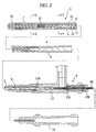
- the basket-type clamping forceps according to the present embodiment is used with an endoscope 2 as shown in FIGS. 1 and 2 .
- a forceps' channel 3A is formed inside of a flexible insertion section 3 in the endoscope 2.
- a port for forceps 3B is formed on the base end of the forceps' channel 3A.
- an operating section 4 for endoscope is connected to the base end of the insertion section 3.
- the basket-type clamping forceps 1 is provided with an flexible operating tube 5 which can be inserted from the port 3B for forceps, an operating wire section 6 which is inserted in the operating tube 5 so as to freely move forwardly and backwardly, a handling section 7 of which base end is connected to the tip of the operating wire section 6 so as to freely open and contract, and an operating section 8 which is connected to the base end of the operating tube so as to open or contract the handling section 7 by a forward and backward movement.
- the handling section 7 are provided with four wire assemblies 13 which are formed by two flexible wires 12 of which tip and the base end are bundled in the tip bundling section 10 and a base end bundling section 11.
- wire assemblies 13 which are formed by two flexible wires 12 of which tip and the base end are bundled in the tip bundling section 10 and a base end bundling section 11.
- seven bending points 15a to 15g and a branch point 16 which branches the flexible wires 12 by intervals with each other are formed in a corresponding position in an axial direction in a middle between the base ends and the tips of these wire assemblies 13.
- the wire assemblies 13 are bent in a first bending point 15a, a sixth bending point 15f, and a seventh bending point 15g are bent under concave bending condition with reference to a central axis C which is an axial line of the handling section 7 which is disposed in a middle of the tip bundling section 10 and the base end bundling section 11 under condition that a bending point which is disposed the nearest to the tip of the wire assembly 13 is a first bending point 15a, a second nearest bending point is a second bending point 15b, a third nearest bending point is a third bending point 15c until a seventh bending point 15g.
- the second bending point (a first convex bending point) 15b and a portion which covers the third bending point (second convex bending point) 15c to the fifth bending pint 15e are bent under a convex bending condition with reference to the central axis C such that three convex bending points are formed in a section which covers the tip bundling section 10 and the branch point 16.
- Each wire assembly 13 is disposed in a three-dimensional relationship in a symmetric manner with reference to the central axis C such that an entire wire assembly should be formed in a basket-like-manner. Also, as shown in FIG. 3B , an angle A2 which is formed by the neighboring flexible wires 12 of the wire assembly 13 and an angle A1 which is formed by the flexible wire 12 which forms a wire assembly 13 are approximately equal when it is views from the tip bundling section 10.
- the convex bending condition indicates a condition under which a bending operation is performed in an approaching direction to the central axis C from the tip to the base end with reference t a linear condition.
- the concave bending condition indicates a condition under which a banding operation is performed in a separating direction in which the base end separates from the central axis C.
- a bending operation is performed in the first bending point 15a by 65 ⁇ 5 degrees with reference to the central axis C outwardly.
- a bending operation is performed in the second bending point by 30 ⁇ 5 degrees with reference to a linear condition. Bending operations are performed in the third bending point 15c and the fourth bending point 15d by 20 ⁇ 5 degrees with reference to the linear condition toward the base end. Also, a bending operation is performed in the seventh bending point 15g by 23 ⁇ 5 degrees with reference to the central axis C outwardly
- Each distance between the bending points are formed as follows. That is, a distance between the first bending point 15a and a second bending point 15b (hereinafter called an interval ab) is formed within a range of 7 ⁇ 2 mm.
- An interval between the second bending point 15b and the third bending point 15c (hereinafter called an interval bc), an interval between the third bending point 15c and the fourth bending point d (hereinafter called an interval cd), and an interval between the forth bending point 15d and the fifth bending point 15e (hereinafter called de) are formed within a range of 9 ⁇ 2 mm such that the distance between the bending points which are formed between the tip bundling section 10 of the flexible wire 12 and the branch point 16 are formed to be approximately equal.
- An interval between the fifth bending point 15e and the sixth bending point 15f (hereinafter called an interval ef) is formed within a range of 12 ⁇ 2 mm. Also, an interval between the second bending points 15b of the flexible wires 12 in each of the wire assembly 13 is set at 3 ⁇ 2 mm. An interval between the third bending points 15c of the flexible wires 12 in each of the wire assembly 13 is set at 5 ⁇ 2 mm.
- the interval which is formed by branching the flexible wire 12 between the base end bundling section 11 and the branch point 16 is branched by 32 ⁇ 5 degrees toward the third bending point 15c from the branch point 16 so as to simultaneously be bent by 24 ⁇ 5 degrees in an approaching direction from a linear condition in the third bending point 15c.
- the branch point 16 is disposed so as to neighbor the fourth bending point 15d such that two flexible wires 12 of the wire assembly 13 are fixed by a fixing agent according to a method such as a brazing operation, a soldering operation, and a bonding agent and thermally-contractive tube.
- two flexible wires 12 are disposed in approximately parallel so as to be near with each other from the base end bundling section 11 to this branch point 16.
- Two flexible wires 12 are disposed so as to expand while separating with each other toward its tip from the branch point 16 to the third bending point 15c.
- Two flexible wires 12 are bundled so as to neighbor with each other toward the tip from the second bending point 15b.
- an interval W2 between the neighboring flexible wires 12 in the different wire assemblies 13 is formed so as to be greater than an interval W1 between each of the flexible wires 12 in a common wire assembly 13 in a first bending point 15b which is formed nearest to the tip of the handling section 7 in a similar manner to a feather of an arrow shaft under a convex bending condition as shown in FIG. 3B .
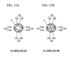
- each flexible wire 12 is formed equally as shown in FIGS. 4A and 4B .
- the operating wire section 8 is provided with a main body 17 which is formed so as to expand in a direction toward the operating wire section 6, a sliding section 18 which is connected to an operating bar member 6A which expands from the base end of the operating wire section so as to be engaged with the main body 17 so as to freely move forwardly and backwardly.
- a through-hole 17A through which the operating bar member 6A can pass is formed in an axial direction of the main body.
- a supporting section 17B in which an operating bar member 6A can slide is disposed on the base end of the main body 17.
- the handling section 7 is inserted in the coelom via the forceps' channel 3A in the insertion section 3 of the endoscope 2 which is inserted in the coelom under condition that the handling section 7 is contained in the operating tube 5. Consequently, the tip of the operating tube 5 is protruded from the tip of the forceps' channel 3A so as to be inserted in, for example, a gallbladder from a papilla duodeni.
- the handling section 7 When the tip of the handling section 7 goes behind a position of the calculus, he Sliging section 18 is operated so as to move forwardly and move the operating wire section 6 forwardly; thus, the handling section 7 is disposed so as to protrude from the tip of the operating tube 5. In such a case, the handling section 7 opens in a basket-like-manner until the handling section 7 contacts an inner wall of the gallbladder by a flexibility force which intends to open each of the bending points 15a to 15g which are formed in each of the wire assemblies 13.
- the basket type clamping forceps according to the present invention contacts the inner wall at the fourth bending point 15d as shown in FIG. 5E .
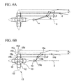
- the basket type clamping forceps of the present invention is provided with the above explained structure, as shown in FIG. 5F , the movement amount L2 of the second bending point inwardly in a radial direction can be restricted to be smaller than the L1 shown in FIG. 5C when the distance is reduced by L length in a direction toward the central axis C similarly to a case shown in FIG. 5C .
- an amount of variance for the interval between each of the flexible wires 12 which are nearer to the tip than the second bending point in the handling section 7 shown in FIG. 6B varies more slightly than that in the conventional handling section 7 which is shown in FIG. 6A .
- the second bending point 15b is under a convex bending condition when the handling section 7 is inserted in the lumen which is an object of biliary; therefore, the handling section 7 hardly bends toward the central axis C. Therefore, it is possible to restrict the movement of the handling section 7 toward the central axis C in a small movement amount. Therefore, the interval W2 between the flexible wires 12 in the neighboring wire assemblies 13 hardly varies at a position which is nearer to the tip than the second bending point 15b; thus, it is possible to restrict the flexible wires 12 from approaching each other.
- the interval W1 between the flexible wires 12 in a wire assembly 13 hardly varies; therefore, it is possible to restrict an inequality in the interval between each of the flexible wires 12.
- an opening angle A1 which is formed between the wire assembly 12 in the flexible wire 12 in a wire assembly 13 and an opening angle A2 which is formed between the flexible wires 12 in the neighboring wire assembly 13 can be maintained so as to be approximately equal under condition that the flexible wire 12 is viewed from the tip of the handling section 7.
- FIGS. 7A and 7B As a comparative example.
- the second embodiment is different from the first embodiment in that the first bending point 22a near the tip bundling section 10 and a second bending point 22b are bent under concave bending condition in a handling section 21 of the basket-type clamping forceps 20 according to the second embodiment.
- eight bending points such as the first bending point 22a to an eighth bending point 22h are formed in corresponding position in the axial direction in a middle of the base end of four of the wire assemblies 13A and the tips.
- a third bending point (first convex bending point) 22c, a fourth bending point (second convex bending point) 22d, a fifth bending point 22e, and a sixth bending point 22f are bent under convex bending condition in a direction to the base end toward the central axis C with reference to the linear condition.
- a distance between the central axis C and the third bending point 22c is 10 mm so as not to be greater than 3/4 of the 20 mm of the distance between the central axis C and the fourth bending point 22d.
- the third bending point 22c and the fourth bending point 22d are formed in a middle of the tip bundling section 10 of the flexible wire 12 and the branch point 16.
- the convex bending point is formed continuously from the third bending point 22c to the sixth bending point 22f.
- the distance between the third bending point 22c and the fourth bending point 22d which is formed in a middle of the tip bundling section 10 of the flexible wire 12 and the branch point 16, the distance between the fourth bending point 22d and the fifth bending point 22e, and the distance between the fifth bending point 22e and the sixth bending point 22f are formed so as to be approximately the same. In the present embodiment, the distance is 9 ⁇ 2 mm.
- the basket-type clamping forceps 20 according to the present embodiment has the same operation and the effect as those in the basket-type clamping forceps 1 according to the first embodiment.
- the handling section 21 contacts an inner wall of the lumen in a position which is nearer to the base end than the fourth bending point 22d which is supposed to be at least the second convex bending point when the handling section 21 is inserted in the lumen which is an object of the biliary. Therefore, the third bending point 22c which is the first convex bending point does not receive a force innermore in a radial direction directly.
- a force which is directed innermore in a radial direction is applied to the handling section 21, a moving amount in each of the bending point under convex bending condition can be restricted in a slight amount.
- the interval W2 between the flexible wires 12 in the neighboring wire assemblies 13 hardly varies at a position which is nearer to the tip than the third bending point 22c which is supposed to be the first convex bending point; thus, it is possible to restrict the flexible wires 12 from approaching each other.
- the interval W1 between the flexible wires 12 in a neighboring wire assembly 13 hardly varies. Therefore, it is possible to restrict an unequal interval between the flexible wires 12. Also, it is possible to maintain the opening angle between the flexible wires 12 in a wire assembly 13 and the opening angle between the flexible wires 12 in a neighboring wire assembly 13 to be approximately equal when it is viewed from a tip of the handling section 21.
- the second bending point 22b is under concave bending condition; therefore, it is possible to alleviate a force for opening and closing which is applied to the first bending point 22a when the bending point 21 opens or contracts; thus, it is possible to restrict a plastic deformation of the flexible wire 12. Therefore, it is possible to prevent an undesirable downsizing of the handling section 21 when the handling section 21 opens or contracts while being re-used.
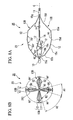
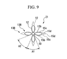
- the third embodiment is different from the first embodiment in that the interval W2 between the neighboring flexible wires 12 of the wire assembly 13B in the handling section 23 is greater than the interval W1 between the flexible wires 12 in the wire assembly 13B among the second bending point 15b in a corresponding position in the axial direction as shown in FIGS. 8A and 8B in the third embodiment.
- the opening angle A1 which is formed by the flexible wires 12 in a wire assembly 13B is smaller than the opening angle A2 which is formed by the flexible wires 12 in the neighboring wire assembly 13b when the handling section 23 is viewed from the tip.
- the basket-type clamping forceps 25 according to the present embodiment has the same effect as that in the basket-type clamping forceps 1 according to the first embodiment.
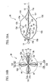
- the opening angle A1 and the opening angle A2 are approximately equal when the handling section 23 is opened in the lumen as shown in FIG. 9B when the handling section 23 is viewed from the tip. Also, it is possible to prevent the clamped calculus, etc. by forming the intervals more equally and reducing a non-dense part and a dense part.
- an outer diameter of a flexible wire 12a in the wire assembly 13C in the handling section 26 may be larger than an outer diameter of the another flexible wire 12b.
- the diameter of another flexible wire 12b is small; therefore, it is possible to maintain a compactness so as to be contained in the operating tube 5.
- a rigidity of the flexible wire 12a is higher than the rigidity of the another flexible wire 12b; therefore, it is possible to increase a force for opening the handling section 26.
- the handling section 26 is opened, it is possible to maintain its opening condition more desirably.
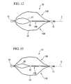
- a further convex bending point 27 is disposed in a middle of the branch point 16 of the wire assembly 13D and the tip bundling section 10 in a handling section 28.
- a convex bending point 30 is disposed in a middle of the branch point 16 of the wire assembly 13E and the tip bundling section 10 in the handling section 31.
- the present invention includes embodiments below.
- an endoscope catheter which comprises a flexible tube, an operating section, a liquid member pouring mouth port, and a finger supporting section 42.
- the flexible tube has at least a lumen.
- the operating section is disposed near the base end of the tube so as to have an inner space which communicates the lumen.
- the finger supporting section 42 is provided with a first aperture section which has an opening section in the inner space on an end of the finger supporting section, a second aperture section which has an opening section outside of the operating section on the other end of the finger supporting section 42, and a liquid member pouring mouth port.
- the finger supporting section 42 is disposed opposite to the liquid member pouring mouth port on the operating section. In this aspect, it is acceptable if the finger supporting section has a pressure dispersing section.
- the other aspect is an endoscope catheter which comprises a flexible tube, an operating section, a liquid member pouring mouth port, and a finger supporting section 42.
- the flexible tube has at least a lumen.
- the operating section is disposed near the base end of the tube so as to have an inner space which communicates the lumen.
- the finger supporting section 42 is provided with a first aperture section which has an opening section in the inner space on an end of the finger supporting section, a second aperture section which has an opening section outside of the operating section on the other end of the finger supporting section 42, and a liquid member pouring mouth port.
- a width of a section which crosses a central axis on an outer surface of the operating section is wider than a width of other section of the operating section.
- the other aspect is an endoscope catheter which comprises a flexible tube, an operating section, a liquid member pouring mouth port, and a finger supporting section 42.
- the flexible tube has at least a lumen.
- the operating section is disposed near the base end of the tube so as to have an inner space which communicates the lumen.
- the finger supporting section 42 is provided with a first aperture section which has an opening section in the inner space on an end of the finger supporting section, a second aperture section which has an opening section outside of the operating section on the other end of the finger supporting section 42, and a liquid member pouring mouth port.
- a thickness of the operating section which is orthogonal to a central axis of the liquid member pouring mouth port is greater than a thickness of the operating section in a central axis direction of the liquid member pouring mouth port.
- the endoscope catheter which has these embodiments is used in a following manner.
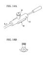
- FIG. 14A is a general view for a basket-type clamping forceps according to the above aspect of the present invention.
- FIG. 14B is a cross section which is viewed in a cross section which is orthogonal to a direction of an arrow shown in FIG. 14A .
- contrast media are poured from a tip of an operation tube liquid member pouring mouth port 41 into the biliary.
- a syringe is connected to the liquid member pouring mouth port 41 so as to pour the contranst media thereinto.
- the viscosity of the contrast media great and a width of the operation tube is narrow. Therefore, an intensive effort is necessary to pour the contrast media by using the syringe. Therefore, an operating section 43 which includes the liquid member pouring mouth port 41 is held by a single hand while a syringe which is connected to the liquid member pouring mouth port 41 is pushed by the other single hand. It is quite painful for a hand which holds the operating section 43; thus, a finger supporting section 42 is disposed opposite to the liquid member pouring mouth port 41.
Landscapes
- Health & Medical Sciences (AREA)
- Surgery (AREA)
- Life Sciences & Earth Sciences (AREA)
- Heart & Thoracic Surgery (AREA)
- Molecular Biology (AREA)
- Vascular Medicine (AREA)
- Engineering & Computer Science (AREA)
- Biomedical Technology (AREA)
- Orthopedic Medicine & Surgery (AREA)
- Medical Informatics (AREA)
- Nuclear Medicine, Radiotherapy & Molecular Imaging (AREA)
- Animal Behavior & Ethology (AREA)
- General Health & Medical Sciences (AREA)
- Public Health (AREA)
- Veterinary Medicine (AREA)
- Surgical Instruments (AREA)
- Endoscopes (AREA)
Claims (5)
- Pince de type à panier (1) comprenant :un tube opérationnel flexible (5) qui peut être inséré dans un canal de pince dans un endoscope (2) ;une section de fils opérationnelle (6) qui est insérée dans le tube opérationnel flexible (5) de manière à être librement mobile vers l'avant et vers l'arrière ;une section de manipulation (7) dont une extrémité de base est connectée à une pointe de la section de fils opérationnelle (6) de manière à s'étendre et se contracter librement, dans laquelle la section de manipulation (7) est prévue avec une pluralité d'ensembles de fils (13), chacun desquels est formé par une pluralité de fils flexibles (12) dont les extrémités de pointe et de base sont réunies respectivement ;dans laquelle une pluralité de points de flexion (15a-15g) et un point de ramification (16) qui ramifie les fils flexibles (12) avec un intervalle les uns par rapport aux autres sont formés dans une région médiane de chacun des ensembles de fils (13) entre l'extrémité de base des ensembles de fils (13) et la pointe des ensembles de fils (13) ;dans laquelle les ensembles de fils (13) sont fléchis sous une condition de flexion concave en référence à une ligne axiale (C) qui est disposée entre la pointe (10) de la section de manipulation (7) et l'extrémité de base de la section de manipulation au niveau d'un premier point de flexion (15a), etcaractérisée en ce que les ensembles de fils (13) sont fléchis en référence à une ligne axiale (C) sous une condition de flexion convexe au niveau d'un deuxième point de flexion (15b), sous la condition que le premier point de flexion (15a) est disposé le plus près de la pointe (10) des ensembles de fils et le deuxième point de flexion (15b) est disposé le deuxième plus près de la pointe (10) des ensembles de fils.
- Pince de type à panier selon la revendication 1, dans laquelle une pluralité de points de flexion convexe (22c-22e) sont formés dans une région médiane entre la section de réunion (10) à la pointe du fil flexible et le point de ramification (16) de façon continue.
- Pince de type à panier selon la revendication 1 ou la revendication 2, dans laquelle les distances entre les points de flexion convexe (22c-22e) qui sont formés entre la section de réunion (10) de la pointe du fil flexible et le point de ramification (16) sont approximativement égales.
- Pince de type à panier selon l'une quelconque des revendications 1 à 3, dans laquelle un intervalle entre les fils flexibles (12) dans les ensembles de fils (13) voisins est formé de manière à être plus grand qu'un intervalle entre les fils flexibles dans les ensembles de fils dans les points de flexion qui est fléchi sous une condition de flexion d'abord à partir de la pointe de la section de manipulation (7).
- Pince de type à panier selon la revendication 1, dans laquelle le point de ramification (16) des fils flexibles (12) est disposé substantiellement au milieu de l'ensemble de fils (13)
Applications Claiming Priority (2)
| Application Number | Priority Date | Filing Date | Title |
|---|---|---|---|
| JP2003323386 | 2003-09-16 | ||
| JP2003323386A JP4384460B2 (ja) | 2003-09-16 | 2003-09-16 | バスケット型把持鉗子 |
Publications (2)
| Publication Number | Publication Date |
|---|---|
| EP1516591A1 EP1516591A1 (fr) | 2005-03-23 |
| EP1516591B1 true EP1516591B1 (fr) | 2008-11-05 |
Family
ID=34191285
Family Applications (1)
| Application Number | Title | Priority Date | Filing Date |
|---|---|---|---|
| EP04021825A Expired - Lifetime EP1516591B1 (fr) | 2003-09-16 | 2004-09-14 | Pince en panier de fils |
Country Status (4)
| Country | Link |
|---|---|
| US (1) | US20050075648A1 (fr) |
| EP (1) | EP1516591B1 (fr) |
| JP (1) | JP4384460B2 (fr) |
| DE (1) | DE602004017554D1 (fr) |
Families Citing this family (10)
| Publication number | Priority date | Publication date | Assignee | Title |
|---|---|---|---|---|
| JP3171115B2 (ja) * | 1996-07-11 | 2001-05-28 | トヨタ車体株式会社 | 車両用スタビライザの支持構造 |
| JP2007061408A (ja) * | 2005-08-31 | 2007-03-15 | Iba:Kk | 運動練習用具 |
| US10076346B2 (en) | 2007-04-17 | 2018-09-18 | Covidien Lp | Complex wire formed devices |
| EP2967610B1 (fr) * | 2013-03-14 | 2018-12-05 | Neuravi Limited | Dispositif de retrait d'un caillot occlusif dans un vaisseau sanguin |
| JP6195733B2 (ja) * | 2013-05-28 | 2017-09-13 | 株式会社リバーセイコー | バスケット把持具 |
| JP6022126B2 (ja) * | 2014-10-07 | 2016-11-09 | オリンパス株式会社 | バスケット型把持鉗子 |
| JP6569206B2 (ja) * | 2014-11-06 | 2019-09-04 | 日本ゼオン株式会社 | 医療用バスケット型処置器具 |
| KR101805296B1 (ko) * | 2016-03-15 | 2017-12-07 | 서울대학교병원 | 인체 내 결석추출 엄브렐라 바스켓 및 이를 포함하는 바스켓 어셈블리 |
| WO2017203669A1 (fr) * | 2016-05-26 | 2017-11-30 | オリンパス株式会社 | Instrument de traitement pour endoscope |
| JP7090104B2 (ja) * | 2018-02-08 | 2022-06-23 | 株式会社カネカ | バスケットカテーテル |
Family Cites Families (6)
| Publication number | Priority date | Publication date | Assignee | Title |
|---|---|---|---|---|
| JPH0698143B2 (ja) * | 1984-06-18 | 1994-12-07 | オリンパス光学工業株式会社 | 体腔内異物の回収具 |
| JPH052166Y2 (fr) * | 1987-07-10 | 1993-01-20 | ||
| US5059199A (en) * | 1989-04-12 | 1991-10-22 | Olympus Optical Co., Ltd. | Treating device for endoscopes |
| JP3075355B2 (ja) * | 1998-02-05 | 2000-08-14 | オリンパス光学工業株式会社 | バスケット型把持鉗子 |
| JP2000005186A (ja) * | 1998-06-18 | 2000-01-11 | Olympus Optical Co Ltd | 内視鏡用処置具 |
| JP3758962B2 (ja) * | 2000-10-11 | 2006-03-22 | ペンタックス株式会社 | 内視鏡用バスケット型回収具 |
-
2003
- 2003-09-16 JP JP2003323386A patent/JP4384460B2/ja not_active Expired - Lifetime
-
2004
- 2004-09-14 US US10/940,551 patent/US20050075648A1/en not_active Abandoned
- 2004-09-14 EP EP04021825A patent/EP1516591B1/fr not_active Expired - Lifetime
- 2004-09-14 DE DE602004017554T patent/DE602004017554D1/de not_active Expired - Lifetime
Also Published As
| Publication number | Publication date |
|---|---|
| DE602004017554D1 (de) | 2008-12-18 |
| EP1516591A1 (fr) | 2005-03-23 |
| JP4384460B2 (ja) | 2009-12-16 |
| US20050075648A1 (en) | 2005-04-07 |
| JP2005087398A (ja) | 2005-04-07 |
Similar Documents
| Publication | Publication Date | Title |
|---|---|---|
| EP1516591A1 (fr) | Pince en panier de fils | |
| JP7560246B2 (ja) | 操縦可能医療デバイスおよび方法 | |
| JP6407495B2 (ja) | 内視鏡 | |
| JP3244660B2 (ja) | 内視鏡用処置具 | |
| US9295807B2 (en) | Method for manufacturing steerable catheter with rapid exchange lumen | |
| US7766821B2 (en) | Bendable portion of an insertion tube of an endoscope and method of producing it | |
| CN103124530A (zh) | 结扎装置和在该结扎装置中使用的夹子单元 | |
| KR20240033268A (ko) | 내시경 또는 침습적 적용을 위한 조향 가능한 기구 | |
| KR20240033269A (ko) | 내시경 또는 침습적 적용을 위한 조향 가능한 기구 | |
| CN111212611A (zh) | 医疗用机械手的挠性管以及弯曲构造体 | |
| CN113316410B (zh) | 用于内窥镜的网篮装置 | |
| JP2020509848A5 (fr) | ||
| WO2006019002A1 (fr) | Instrument pour monter un tuyau annelé | |
| US10349962B2 (en) | Endoscope treatment tool | |
| JPWO2006080113A1 (ja) | 生体管内治療具 | |
| US10932801B2 (en) | Endoscope treatment tool | |
| US20170246431A1 (en) | Medical instrument | |
| CN113349705A (zh) | 成像导管、端头、管体和医疗设备 | |
| EP4497399A1 (fr) | Élément de préhension monobloc et procédé de fabrication | |
| JP4933772B2 (ja) | 内視鏡用ガイドチューブ及び内視鏡装置 | |
| JP7692926B2 (ja) | 内視鏡用スネア装置 | |
| JP4412429B2 (ja) | 内視鏡のアングル部 | |
| JP2022085043A (ja) | 保護チューブ及びワイヤハーネス | |
| JPS63186641A (ja) | 内視鏡用把持鉗子 | |
| JP2005204807A (ja) | バスケット型把持鉗子 |
Legal Events
| Date | Code | Title | Description |
|---|---|---|---|
| PUAI | Public reference made under article 153(3) epc to a published international application that has entered the european phase |
Free format text: ORIGINAL CODE: 0009012 |
|
| AK | Designated contracting states |
Kind code of ref document: A1 Designated state(s): AT BE BG CH CY CZ DE DK EE ES FI FR GB GR HU IE IT LI LU MC NL PL PT RO SE SI SK TR |
|
| AX | Request for extension of the european patent |
Extension state: AL HR LT LV MK |
|
| 17P | Request for examination filed |
Effective date: 20050428 |
|
| AKX | Designation fees paid |
Designated state(s): DE FR GB IE |
|
| 17Q | First examination report despatched |
Effective date: 20070208 |
|
| GRAP | Despatch of communication of intention to grant a patent |
Free format text: ORIGINAL CODE: EPIDOSNIGR1 |
|
| RIN1 | Information on inventor provided before grant (corrected) |
Inventor name: KOMIYA, TAKAAKI |
|
| GRAS | Grant fee paid |
Free format text: ORIGINAL CODE: EPIDOSNIGR3 |
|
| GRAA | (expected) grant |
Free format text: ORIGINAL CODE: 0009210 |
|
| AK | Designated contracting states |
Kind code of ref document: B1 Designated state(s): DE FR GB IE |
|
| REG | Reference to a national code |
Ref country code: GB Ref legal event code: FG4D |
|
| REG | Reference to a national code |
Ref country code: IE Ref legal event code: FG4D |
|
| REF | Corresponds to: |
Ref document number: 602004017554 Country of ref document: DE Date of ref document: 20081218 Kind code of ref document: P |
|
| PLBE | No opposition filed within time limit |
Free format text: ORIGINAL CODE: 0009261 |
|
| STAA | Information on the status of an ep patent application or granted ep patent |
Free format text: STATUS: NO OPPOSITION FILED WITHIN TIME LIMIT |
|
| 26N | No opposition filed |
Effective date: 20090806 |
|
| PGFP | Annual fee paid to national office [announced via postgrant information from national office to epo] |
Ref country code: IE Payment date: 20140909 Year of fee payment: 11 |
|
| PGFP | Annual fee paid to national office [announced via postgrant information from national office to epo] |
Ref country code: GB Payment date: 20140910 Year of fee payment: 11 |
|
| PGFP | Annual fee paid to national office [announced via postgrant information from national office to epo] |
Ref country code: FR Payment date: 20140906 Year of fee payment: 11 |
|
| GBPC | Gb: european patent ceased through non-payment of renewal fee |
Effective date: 20150914 |
|
| REG | Reference to a national code |
Ref country code: IE Ref legal event code: MM4A |
|
| REG | Reference to a national code |
Ref country code: FR Ref legal event code: ST Effective date: 20160531 |
|
| PG25 | Lapsed in a contracting state [announced via postgrant information from national office to epo] |
Ref country code: IE Free format text: LAPSE BECAUSE OF NON-PAYMENT OF DUE FEES Effective date: 20150914 Ref country code: GB Free format text: LAPSE BECAUSE OF NON-PAYMENT OF DUE FEES Effective date: 20150914 |
|
| PG25 | Lapsed in a contracting state [announced via postgrant information from national office to epo] |
Ref country code: FR Free format text: LAPSE BECAUSE OF NON-PAYMENT OF DUE FEES Effective date: 20150930 |
|
| P01 | Opt-out of the competence of the unified patent court (upc) registered |
Effective date: 20230528 |
|
| PGFP | Annual fee paid to national office [announced via postgrant information from national office to epo] |
Ref country code: DE Payment date: 20230920 Year of fee payment: 20 |
|
| REG | Reference to a national code |
Ref country code: DE Ref legal event code: R071 Ref document number: 602004017554 Country of ref document: DE |