EP1516527A2 - Ballenpresse, Verbindungsstange und Presskolben - Google Patents
Ballenpresse, Verbindungsstange und Presskolben Download PDFInfo
- Publication number
- EP1516527A2 EP1516527A2 EP04104447A EP04104447A EP1516527A2 EP 1516527 A2 EP1516527 A2 EP 1516527A2 EP 04104447 A EP04104447 A EP 04104447A EP 04104447 A EP04104447 A EP 04104447A EP 1516527 A2 EP1516527 A2 EP 1516527A2
- Authority
- EP
- European Patent Office
- Prior art keywords
- plunger
- sensors
- connecting rod
- piston
- baler
- Prior art date
- Legal status (The legal status is an assumption and is not a legal conclusion. Google has not performed a legal analysis and makes no representation as to the accuracy of the status listed.)
- Granted
Links
- 230000006835 compression Effects 0.000 description 4
- 238000007906 compression Methods 0.000 description 4
- 238000004519 manufacturing process Methods 0.000 description 4
- 239000000463 material Substances 0.000 description 3
- 230000000694 effects Effects 0.000 description 2
- 238000005259 measurement Methods 0.000 description 2
- 230000003014 reinforcing effect Effects 0.000 description 2
- 230000035945 sensitivity Effects 0.000 description 2
- 240000003517 Elaeocarpus dentatus Species 0.000 description 1
- 230000001133 acceleration Effects 0.000 description 1
- 230000006978 adaptation Effects 0.000 description 1
- 238000005452 bending Methods 0.000 description 1
- 230000000903 blocking effect Effects 0.000 description 1
- 238000005056 compaction Methods 0.000 description 1
- 230000000295 complement effect Effects 0.000 description 1
- 238000001514 detection method Methods 0.000 description 1
- 210000002023 somite Anatomy 0.000 description 1
- 238000001228 spectrum Methods 0.000 description 1
- 238000011144 upstream manufacturing Methods 0.000 description 1
Images


Classifications
-
- A—HUMAN NECESSITIES
- A01—AGRICULTURE; FORESTRY; ANIMAL HUSBANDRY; HUNTING; TRAPPING; FISHING
- A01F—PROCESSING OF HARVESTED PRODUCE; HAY OR STRAW PRESSES; DEVICES FOR STORING AGRICULTURAL OR HORTICULTURAL PRODUCE
- A01F15/00—Baling presses for straw, hay or the like
- A01F15/04—Plunger presses
- A01F15/042—Plungers
-
- A—HUMAN NECESSITIES
- A01—AGRICULTURE; FORESTRY; ANIMAL HUSBANDRY; HUNTING; TRAPPING; FISHING
- A01F—PROCESSING OF HARVESTED PRODUCE; HAY OR STRAW PRESSES; DEVICES FOR STORING AGRICULTURAL OR HORTICULTURAL PRODUCE
- A01F15/00—Baling presses for straw, hay or the like
- A01F15/08—Details
- A01F15/0825—Regulating or controlling density or shape of the bale
-
- A—HUMAN NECESSITIES
- A01—AGRICULTURE; FORESTRY; ANIMAL HUSBANDRY; HUNTING; TRAPPING; FISHING
- A01F—PROCESSING OF HARVESTED PRODUCE; HAY OR STRAW PRESSES; DEVICES FOR STORING AGRICULTURAL OR HORTICULTURAL PRODUCE
- A01F15/00—Baling presses for straw, hay or the like
- A01F15/08—Details
- A01F15/10—Feeding devices for the crop material e.g. precompression devices
- A01F15/101—Feeding at right angles to the compression stroke
-
- Y—GENERAL TAGGING OF NEW TECHNOLOGICAL DEVELOPMENTS; GENERAL TAGGING OF CROSS-SECTIONAL TECHNOLOGIES SPANNING OVER SEVERAL SECTIONS OF THE IPC; TECHNICAL SUBJECTS COVERED BY FORMER USPC CROSS-REFERENCE ART COLLECTIONS [XRACs] AND DIGESTS
- Y10—TECHNICAL SUBJECTS COVERED BY FORMER USPC
- Y10T—TECHNICAL SUBJECTS COVERED BY FORMER US CLASSIFICATION
- Y10T29/00—Metal working
- Y10T29/49—Method of mechanical manufacture
- Y10T29/49229—Prime mover or fluid pump making
- Y10T29/49288—Connecting rod making
-
- Y—GENERAL TAGGING OF NEW TECHNOLOGICAL DEVELOPMENTS; GENERAL TAGGING OF CROSS-SECTIONAL TECHNOLOGIES SPANNING OVER SEVERAL SECTIONS OF THE IPC; TECHNICAL SUBJECTS COVERED BY FORMER USPC CROSS-REFERENCE ART COLLECTIONS [XRACs] AND DIGESTS
- Y10—TECHNICAL SUBJECTS COVERED BY FORMER USPC
- Y10T—TECHNICAL SUBJECTS COVERED BY FORMER US CLASSIFICATION
- Y10T403/00—Joints and connections
- Y10T403/55—Member ends joined by inserted section
- Y10T403/553—Laterally inserted section
-
- Y—GENERAL TAGGING OF NEW TECHNOLOGICAL DEVELOPMENTS; GENERAL TAGGING OF CROSS-SECTIONAL TECHNOLOGIES SPANNING OVER SEVERAL SECTIONS OF THE IPC; TECHNICAL SUBJECTS COVERED BY FORMER USPC CROSS-REFERENCE ART COLLECTIONS [XRACs] AND DIGESTS
- Y10—TECHNICAL SUBJECTS COVERED BY FORMER USPC
- Y10T—TECHNICAL SUBJECTS COVERED BY FORMER US CLASSIFICATION
- Y10T74/00—Machine element or mechanism
- Y10T74/21—Elements
- Y10T74/2142—Pitmans and connecting rods
Definitions
- the invention relates to a baler with a rectangular press chamber in which a plunger movable is received, with a feed opening through which well in the pressing chamber can be promoted to there by the Compressive piston to be compressed, with one with the plunger connected piston drive with a pair of transversely spaced, at least when the plunger is at least substantially fully extended into an end region of the baling chamber is at least substantially horizontally oriented Connecting rods and a sensor device for detection of acting on the plunger and / or the piston drive Loads, with at least two laterally from each other spaced with the piston drive and / or the piston interacting sensors, as well as a connecting rod of a Piston drive a baler and a plunger and / or a piston drive of such a baler.
- Baling presses for the production of large, rectangular bales often have a pre-compression chamber in the form of a curved Shaft or feed channel on, accumulated in the crop is due to until it has reached a predetermined density the one loading fork device is actuated to a portion from crop to a baling chamber at one point behind or on to introduce the plunger adjacent to the press chamber.
- the plunger compacts the crop against already previously compacted crop, already in the Press chamber is located and adjustable against the effect Side walls, which set the cross-section of the pressing chamber, to limit the movement of the crop and so on Achieve that one bale with a predetermined density will be produced.
- this force represents the density. Because the density of Entegutladung or -portion, which in the pressing chamber is introduced, may differ from right to left is It is known to take force measurements on each side of a pair of laterally spaced connecting rods perform which between a drive of the plunger and the Extend plunger. Using the determined Measurements will generate a signal to an operator to inform about a need to Direction of travel of the baler after one or the other Page to change to a Erntegutschwad to cause an extra amount of crop on the Side into the baler on which the lower Measured value of the force required for compaction has been determined.
- US-A-4,627,341, US-A-5,253,570 and EP-B1-0,223,351 show appropriately trained balers, which sensors have, in laterally spaced connecting rods a piston drive are integrated to the one on forming bales of acting force and signals which are used in a control system to generate a To assist the operator in making bales more uniform To produce density.
- the sensors are arranged such that they are in a central, horizontal plane that runs through the Connecting rods extends when the plunger during a compression stroke in a fully backward extended position, lie.
- balers of different sizes Plunger loads that are proportional to the lateral Cross-sectional area are that between the opposite Side walls of the pressing chamber is arranged. Will the sensor or the load-sensing pin is too strong, so goes a part lost the possible data resolution of the sensor. Corresponding need balers manufacturers of different sizes Sensors or load measuring pins of different sizes or Sensitivity, which increases costs.
- balers for the production cuboid bales often no bales of optimal homogeneity produce.
- the Sensor device has at least two laterally from each other spaced with the piston drive and / or the piston interacting sensors that provide data or values can determine the distribution of the material to be pressed in the baling chamber represent.
- the values or data can be used to draw conclusions about the distribution of the data Allow pressed material based on the width of the pressing chamber.
- the sensor device can also Information about the distribution of the crop in vertical Direction or related to the height of the press room supply.
- These data or values can be, for example, a Operator or transmitted to them so that they an adaptation of functions or parameters of the baler can make so that the baler a possible forms homogeneous bales.
- the connecting rods each have one preferably arranged in their end regions Connecting bolt certain longitudinal central axes, which at at least substantially extended plunger a at least essentially defining a horizontal plane that between an upper and a lower wall of the Press chamber extends.
- the sensors can be general vertical be arranged spaced or staggered, in particular but related to these longitudinal center lines or the plane staggered.
- the sensors can be of any type of sensor, in particular digital or analogue design. A particularly simple design results, however, if at least one of the sensors in the manner of a load or load measuring pin is formed and / or has such.
- At least one of the connecting rods is at least in two parts trained, their subregions can by means of vertical be connected spaced fastener, of which at least one of the sensors has or as a such, in particular as a load measuring pin, is formed.
- one of the subregions is an end region of the connecting rod, which preferably a bearing, in particular in the manner of a Spherical bearing, this may have a connecting bolt or record one of the connecting bolts, so that this End region connects to the plunger.
- the sections are particularly easy to connect, if at least one part of a spring and the other Part having at least one corresponding groove.
- the plunger may also be a few laterally spaced Having plates for fixing the connecting rods, which releasably with the rest of the plunger by means of first and second vertically spaced fastener connected at least one of which has the sensor and / or as one of the sensors, especially in the way of a Load measuring bolt, may be formed.
- These plates can be triangular and / or as one be formed equilateral triangle, wherein the first and second vertically spaced fastener in corresponding first and second corner areas of a respective Plate are arranged and each plate a third corner area having, with a rear end portion of the respective Connecting rod is pivotally connected. It is also any other suitable geometry, in particular a training as an isosceles triangle, conceivable, being the base of the isosceles triangle preferably with the plunger is connected by means of the fastening means.
- the first and second fastening means vertically aligned and preferably a same distance from have the level.
- a connecting rod which is a preferably central Longitudinal axis and at least a first and a second bearing, in particular in the form of spherical bearings, which are used in opposite end portions of the connecting rod are arranged, and a first and a second portion which has a connection between the bearings manufacture, wherein the subregions by at least two Fasteners are connected, of which at least one a sensor, preferably in the nature of a load-sensing pin is or is formed by such, based on the Longitudinal central axis and / or the further fastening means can be arranged as a spare part for one Serve piston drive a previously described baler or a known piston drive of a conventional Baler for producing cuboid bales in such a way complement or be retrofitted to such a way that a sensor device of the baler not only data / values can supply a distribution of the crop related to the width of the pressing chamber but also at its height or provide vertical extension.
- FIG. 1 is a Baler 10 for the production of large, rectangular bales shows, which has a main frame 12 which extends over wheels 14 is supported on the ground, which in the manner of a Tandem tires are arranged. From a front area of the Main frame 12 extends a drawbar 16 away, the thereto adapted to a towing vehicle, such as a Agricultural tractors (not shown), to be connected.
- a pressing chamber 18 has parallel upper and lower walls 20 and 22, and opposite, parallel side walls, all of which are arranged such that they have a square or rectangular cross section form.
- the lower wall 22 has a Guteinlass 24, which with an upper end portion of a pre-compression chamber or a feed channel 26 in the form of an upwardly curved Schacht, the upstream of a pick-up or a Collecting device 28 is arranged, is connected.
- a compressor fork assembly 30 provided, which acts so that he harvested in one front end portion of the supply channel 26 moves.
- crosswise spaced tines 32 of a pivotally mounted one Good entry blocking fork 34 are selectively between a shown, crop restrained position in which they are an upper edge of a rear wall of the feed channel 26 out, at a position adjacent to the Guteinlass 24 extend, and one pivoted backwards Guteinlass too can be moved, in which they are one allow accumulated amount of good, by operating a Loading fork 36 to be moved into the pressing chamber 18, which having transversely spaced forks extending in slots move down in a front wall of the feed channel 26th are provided, and then through the supply channel 26 upwards sweep to the crop or portion in the pressing chamber 18 to move.
- the fork 34 and the loading fork 36 are suitable Assigned actuating means (not shown), which with Control means interact, which are clocked to a Pulling back the fork 34 and then pressing the Charging fork 36 effect as soon as the good quantity or charge a has reached preselected density, which by a Sensor device 38 in the manner of a spring-loaded flap is determined.
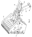
- FIG. 2 is the Piston drive 40 shows that a retractable and retractable Hydraulic motor 50 has, whose Zylinderend Scheme on the Frame 12 is anchored by means of a connecting bolt 52, and its Kolbenend Scheme pivotally by means of a bolt 54th is connected to a crank arm 56.
- the crank arm 56 is fastened so that it is about a horizontal transverse axis oscillated, which is determined by a bolt 58, a front end portion of the crank arm 56 with the Main frame 12 connects.
- a rear end portion 56 of the Crank arm 56 is pivotable, for example by means of a Connecting bolt 60, at a front end portion of a parallel pair of laterally spaced connecting rods or Connecting rods 62 connected, the rear end portions pivotable with the plunger 42 by means of appropriate Connecting bolts 64 are connected.
- the hydraulic motor 50 is shown in its retracted position in Figure 2 with corresponds to the position it occupies when the Pressing piston 42 in the pressing chamber 18 completely to the rear is extended.
- each of the connecting rods 62 correspond with transverse bores are provided, in which identical, front and rear Self-aligning ball bearings or spherical plain bearings with a connecting line, which are referred to below as bearings 74 and 76, are arranged.
- Each connecting rod 62 has a separate front end area 78 on, which by a profile with rectangular section is determined, in which a bore or recess is arranged, which the front bearing 74th includes.
- the front end portion 78 has a tongue or spring 80 lesser width, which between opposite Sides of a bifurcated front end portion of the remaining Area of the connecting rod 62 is arranged.
- End region 78 is characterized by a load measuring pin or sensor executed first fastener 82 and another Bolt or another fastening means 84 secured in position, wherein the first attachment means 82 and the second Fastener 84 corresponding to the connecting line C ' spaced up and down.
- FIG 4 is a load analysis one of the connecting rods 62 shows. Since the bearings 74 and 76 are provided at each end portion of the connecting rod 62, the connecting rod 62 is no bending loads, but only pressure loads F experienced. The stress path will be always through the center of each roll of bearings 74 and 76 extend.
- the distance of the load path from the sensor or the first attachment means 82 is L1
- the Distance between the second fastener 84 and the Load path L2 is. Accordingly, the ratio (L1 / L2) the distance between the load path and the first Fastener 82 and the second fastener 84, in the first fastener 82 and the second Fixing means 84 determined force.
- the connecting rod 62 may be formed be that they have the entire load spectrum of one already available sensor, allowing the electronic Sensitivity of the sensor designed as Fastener 82 is maximized.
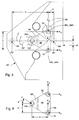
- the plate 86 is here in the manner of a formed with an equilateral triangle, with two vertices vertical aligned with each other and vertically spaced equally arranged opposite sides of a central plane C. are, and where the remaining corner in front of the other corners and is arranged centrally on the level C.
- the right and left triangular plates 86 are correspondingly right and left left pairs of plate - like, vertical ribs of the Plunger 42 'is added, of which only the left pair of Ribs 88 is visible.
- a first as load measuring pin or Sensor formed fastener 90L extends by aligned recesses in the pair of ribs 88 and a bearing 92, which in an upper, rear Corner region of the triangular plate 86 is arranged. It should become clear that another as force measuring pin or Sensor trained fastener 90R (not visible) alike is provided to the upper, rear Corner of the right triangular plate on the right pair plate-like reinforcing ribs of the plunger 42 'to to back up. In the same way, a left bolt extends or a fastening means 94L by aligned recesses in the pair of ribs 88 and a bearing 96 in a lower, rear corner portion of the triangular plate 86.
- a right fastening means 94R (not shown) by aligned recesses in the right pair Reinforcing ribs and a bearing that a lower, rear corner area of the right triangular plate certainly.
- a front portion of the triangular plate 86 bifurcated so as to determine a front corner area, the parallel, laterally spaced sides 98 having, with a bearing 100 are provided, the bearings 100th cooperate to the front corner regions of the plate 86 to determine.
- the rear end of the left Connecting rod 62 ' is between spaced sides 98 of the received at the front portion of the plate 86, and at this by a bolt 102, which is centered in the plane C. secured.
- the connecting rods 62 ' take the bearings 74 and 76 corresponding in their front and rear end portions on.
- the plunger / Connecting rod / plate assembly of the second Embodiment the same ability to determine lateral Has load difference of a plunger, like the Plunger / connecting rod assembly according to the first Embodiment and further has the ability to Determine load difference from top to bottom.
Landscapes
- Life Sciences & Earth Sciences (AREA)
- Environmental Sciences (AREA)
- Preliminary Treatment Of Fibers (AREA)
- Force Measurement Appropriate To Specific Purposes (AREA)
- Actuator (AREA)
- Scissors And Nippers (AREA)
- Hydraulic Motors (AREA)
Abstract
Description
- Fig. 1
- eine schematische Ansicht einer Ballenpresse zur Herstellung großer, quaderförmiger Ballen mit einem in einer Presskammer beweglich angeordneten Presskolben,
- Fig. 2
- eine vergrößerte, perspektivische Ansicht des Presskolbens und eines Antriebs des Presskolbens mit Sensoren aufweisenden Verbindungsstangen gemäß einer ersten Ausführungsform der Erfindung,
- Fig. 3
- eine vergrößerte, perspektivische Ansicht einer der Verbindungsstangen,
- Fig. 4
- einen Längsschnitt durch die Verbindungsstange entlang der Linie 4-4 aus Figur 3,
- Fig. 5
- eine Seitenansicht eines alternativ ausgeführten Presskolbens, der auf jeder Seite eine dreieckige Platte aufweist, welche mit dem Presskolben und einem Kolbenantrieb mittels Sensoren aufweisenden Befestigungsmitteln verbunden ist und
- Fig. 6
- eine Seitenansicht der Platte aus Figur 5 unter Darstellung, der an ihr angreifenden Kräfte.
Claims (11)
- Ballenpresse (10) mit einer quaderförmigen Presskammer (18), in der ein Presskolben (42, 42') beweglich aufgenommen wird, mit einer Zufuhröffnung (24) durch welche Gut in die Presskammer (18) gefördert werden kann, um dort durch den Presskolben (42, 42') verdichtet zu werden, mit einem mit dem Presskolben (42, 42') verbundenen Kolbenantrieb (40) mit einem Paar quer beabstandeter, sich zumindest, wenn der Presskolben (42, 42') zumindest im Wesentlichen vollständig in einen Endbereich der Presskammer (18) ausgefahren ist, wenigstens im Wesentlichen horizontal ausgerichteter Verbindungsstangen (62, 62') und einer Sensoreinrichtung zur Ermittlung von auf den Presskolben (42, 42') und/oder den Kolbenantrieb (40) wirkenden Belastungen, mit wenigstens zwei seitlich voneinander beabstandeten mit dem Kolbenantrieb (40) und/oder dem Presskolben (42) zusammenwirkenden Sensoren, dadurch gekennzeichnet dass einer der Sensoren bezogen auf den anderen Sensor zumindest bei vollständig ausgefahrenem Presskolben (18) vertikal versetzt angeordnet ist.
- Ballenpresse nach Anspruch 1, dadurch gekennzeichnet, dass die Verbindungsstangen (62, 62') jeweils eine vorzugsweise durch in ihren Endbereichen angeordnete Verbindungsbolzen (60, 64) bestimmte Längsmittelachsen (C') aufweisen, welche bei zumindest im Wesentlichen ausgefahrenem Presskolben (18) eine zumindest im Wesentlichen horizontale Ebene (C) definieren, die sich zwischen einer oberen und einer unteren Wand (20, 22) der Presskammer (18) erstreckt, und dass die Sensoren bezogen auf die Längsmittellinien bzw. die Ebene (C) versetzt angeordnet sind
- Ballenpresse nach Anspruch 1 oder 2, dadurch gekennzeichnet, dass wenigstens einer der Sensoren in der Art eines Kraftmessbolzens ausgebildet ist und/oder einen solchen aufweist.
- Ballenpresse nach einem oder mehreren der vorherigen Ansprüche, dadurch gekennzeichnet, dass wenigstens eine der Verbindungsstangen (62, 62') zweiteilig ausgebildet und ihre Teilbereiche mittels vertikal beabstandeter Befestigungsmittel (82, 84) verbunden sind, wobei wenigstens eines der Befestigungsmittel (82, 84) vorzugsweise einen der Sensoren aufweist bzw. als ein solcher ausgebildet ist.
- Ballenpresse nach Anspruch 4, dadurch gekennzeichnet, dass einer der Teilbereich ein Endbereich (78) der Verbindungsstange (62) ist, welcher vorzugsweise ein Lager (74, 76), insbesondere in der Art eines Gelenklagers aufweist, das einen bzw. einen der Verbindungsbolzen (64) aufnehmen kann, der den Endbereich (78) mit dem Presskolben (42) verbindet.
- Ballenpresse nach Anspruch 4 oder 5, dadurch gekennzeichnet, dass wenigstens einer der Teilbereiche wenigstens eine Feder (80) und der andere Teilbereich wenigstens eine korrespondierende Nut aufweist.
- Ballenpresse nach einem oder mehreren der Ansprüche 1 bis 3, dadurch gekennzeichnet, dass der Presskolben (18) ein paar seitlich beabstandeter Platten (86) zur Befestigung der Verbindungsstangen (62, 62') aufweist, welche lösbar mit dem übrigen Presskolben (42') mittels erster und zweiter vertikal beabstandeter Befestigungsmittel (90, 94) verbunden sind, und wobei wenigstens eines der Befestigungsmittel (90, 94) einen der Sensoren aufweist und/oder als einer der Sensoren ausgebildet ist.
- Ballenpresse nach Anspruch 7, dadurch gekennzeichnet, dass die Platten (86) dreieckig sind und/oder ein gleichseitiges Dreieck bilden, wobei die ersten und zweiten vertikal beabstandeten Befestigungsmittel (90, 94) in entsprechenden ersten und zweiten Eckbereichen einer jeweiligen Platte (86) angeordnet sind und jede Platte (86) einen dritten Eckbereich aufweist, der mit einem rückwärtigen Endbereich (78) der jeweiligen Verbindungsstange (62, 62') schwenkbar verbunden ist.
- Ballenpresse nach Anspruch 8, dadurch gekennzeichnet, dass die ersten und zweiten Befestigungsmittel (90, 94) vertikal fluchten und einen vorzugsweise gleichen Abstand von der Ebene (C) aufweisen.
- Verbindungsstange (62) eines Kolbenantriebs einer Ballenpresse nach einem oder mehreren der Ansprüche 1 bis 6, dadurch gekennzeichnet, dass die Verbindungsstange (62, 62') eine vorzugsweise zentrale Längsachse (C') und wenigstens ein erstes und ein zweites Lager (74, 76), insbesondere in der Art von Gelenklagern, aufweist, die in gegenüberliegenden Endbereichen der Verbindungsstange (62, 62') angeordnet sind, dass die Verbindungsstange (62, 62') einen ersten und einen zweiten Teilbereich aufweist, welche eine Verbindung zwischen den Lagern (74, 76) herstellen und dass die Teilbereiche durch wenigstens zwei Befestigungsmittel (82, 84) verbunden sind, von denen wenigstens eines ein Sensor, vorzugsweise in der Art eines Lastmessbolzens, ist bzw. durch einen solchen gebildet wird, der bezogen auf die Längsmittelachse (C') und/oder das weitere Befestigungsmittel (82, 84) versetzt angeordnet ist.
- Presskolben (40, 42') und/oder Kolbenantrieb (40) einer Ballenpresse (10) nach einem oder mehreren der Ansprüche 1 bis 8.
Applications Claiming Priority (2)
| Application Number | Priority Date | Filing Date | Title |
|---|---|---|---|
| US665218 | 1984-10-26 | ||
| US10/665,218 US7007599B2 (en) | 2003-09-17 | 2003-09-17 | Baler plunger drive load measurement pin offset from either connecting rod center line or horizontal mid-plane of baling chamber |
Publications (3)
| Publication Number | Publication Date |
|---|---|
| EP1516527A2 true EP1516527A2 (de) | 2005-03-23 |
| EP1516527A3 EP1516527A3 (de) | 2005-06-08 |
| EP1516527B1 EP1516527B1 (de) | 2006-12-27 |
Family
ID=34194762
Family Applications (1)
| Application Number | Title | Priority Date | Filing Date |
|---|---|---|---|
| EP04104447A Expired - Lifetime EP1516527B1 (de) | 2003-09-17 | 2004-09-15 | Ballenpresse, Verbindungsstange und Presskolben |
Country Status (3)
| Country | Link |
|---|---|
| US (3) | US7007599B2 (de) |
| EP (1) | EP1516527B1 (de) |
| DE (1) | DE502004002421D1 (de) |
Cited By (1)
| Publication number | Priority date | Publication date | Assignee | Title |
|---|---|---|---|---|
| WO2013186188A1 (en) | 2012-06-12 | 2013-12-19 | Cnh Belgium N.V. | Agricultural square baler |
Families Citing this family (22)
| Publication number | Priority date | Publication date | Assignee | Title |
|---|---|---|---|---|
| DE102007011489A1 (de) * | 2007-03-07 | 2008-09-11 | Kiefel Gmbh | Überlastsicherung, Antriebsstrang mit einer derartigen Überlastsicherung, Vorrichtung zum Herstellen und/oder Bearbeiten eines Werkstückes sowie Verfahren zum Aufbringen von Arbeitskräften |
| US8069780B2 (en) * | 2009-03-25 | 2011-12-06 | Deere & Company | Modular baler plunger |
| US7707932B1 (en) * | 2009-05-05 | 2010-05-04 | Cnh America Llc | Staggered plunger tail with improved wear surface for a small square baler |
| US9204596B2 (en) * | 2010-04-14 | 2015-12-08 | Kuhn-Geldrop B.V. | Plunger press and method for producing compressed bales |
| US9167750B2 (en) | 2011-12-28 | 2015-10-27 | Agco Corporation | Stuffer chute fill indicator |
| BE1020523A3 (nl) * | 2012-03-14 | 2013-12-03 | Cnh Belgium Nv | Een methode en een systeem voor het bepalen van de belasting op een onderdeel van het aandrijfsysteem van een plunjer in een balenpers. |
| BE1021133B1 (nl) * | 2013-02-21 | 2016-01-05 | Cnh Industrial Belgium Nv | Landbouwbalenpers met vliegwielremsturing |
| BE1021165B1 (nl) | 2013-11-08 | 2016-01-15 | Cnh Industrial Belgium Nv | Werkwijze voor het testen van een balenpers voor gebruik in de landbouw |
| US9736988B2 (en) * | 2014-01-30 | 2017-08-22 | Deere & Company | Baler plunger-position sensor assembly and method |
| US9192104B1 (en) * | 2014-05-07 | 2015-11-24 | Deere & Company | Lift link overload protection assembly |
| DE102016218595A1 (de) | 2016-09-27 | 2018-03-29 | Deere & Company | Antriebssystem eines Arbeitsfahrzeugs |
| US11013184B2 (en) | 2016-10-12 | 2021-05-25 | Deere & Company | Baler with pressure transducer |
| US10674674B2 (en) * | 2016-10-12 | 2020-06-09 | Deere & Company | Baler with lockout valve |
| US10568270B2 (en) | 2016-10-12 | 2020-02-25 | Deere & Company | Baler with variable length connector rod |
| US10525650B2 (en) | 2017-10-18 | 2020-01-07 | Deere & Company | Baler plunger guide system |
| US11369061B2 (en) * | 2018-06-26 | 2022-06-28 | Deere & Company | Agricultural baler with mechanisms for producing crop bales |
| EP3646711B1 (de) * | 2018-11-02 | 2021-08-25 | CNH Industrial Belgium NV | Landwirtschaftliche ballenpresse mit rahmenlosem und schweissnahtfreiem kolben |
| EP3646712B1 (de) * | 2018-11-02 | 2024-01-10 | CNH Industrial Belgium NV | Verbesserungen an oder im zusammenhang mit landwirtschaftlichen ballenpressen |
| EP3646718B1 (de) * | 2018-11-02 | 2023-07-12 | CNH Industrial Belgium NV | Verbesserungen an oder im zusammenhang mit landwirtschaftlichen ballenpressen |
| US11140830B2 (en) | 2019-01-09 | 2021-10-12 | Great Plains Manufacturing, Inc. | High capacity baler with multiple knotters |
| US11882793B2 (en) | 2020-07-16 | 2024-01-30 | Deere & Company | System and method for estimating or predicting the life state of components in an agricultural baler |
| DE102024119535A1 (de) | 2024-07-10 | 2026-01-15 | Usines Claas France S.A.S. | Landwirtschaftliche Ballenpresse |
Citations (3)
| Publication number | Priority date | Publication date | Assignee | Title |
|---|---|---|---|---|
| US4627341A (en) | 1985-09-06 | 1986-12-09 | New Holland, Inc. | Bale density control sensing apparatus and method |
| EP0223351B1 (de) | 1985-09-06 | 1991-04-03 | FORD NEW HOLLAND, INC. (a Delaware corp.) | Elektronische Vorrichtung zum Messen und Steuern beim Verdichten von Erntegut |
| US5253570A (en) | 1983-09-30 | 1993-10-19 | Hay & Forage Industries | Baler with load sensor |
Family Cites Families (7)
| Publication number | Priority date | Publication date | Assignee | Title |
|---|---|---|---|---|
| US5226356A (en) * | 1983-09-30 | 1993-07-13 | Hay & Forage Industries | Reciprocating plunger crop baler having monitoring system for checking uniformity of loaded charges |
| FR2643785B1 (fr) | 1989-03-03 | 1992-02-07 | Hesston Braud | Procede et dispositif de regulation de densite pour ramasseuse-presse a balles parallelepipediques |
| DE4312991A1 (de) | 1993-04-21 | 1994-10-27 | Sacht Hans Otto Dr Ing | Verfahren und Presse zum Bilden quaderförmiger Preßballen aus landwirtschaftlichem Erntegut |
| KR0176682B1 (ko) * | 1996-04-23 | 1999-10-01 | 김광호 | 왕복동식 압축기 |
| GB2330110A (en) * | 1997-10-07 | 1999-04-14 | Ford New Holland Nv | Bale density control system for agricultural balers |
| US5950410A (en) | 1998-03-03 | 1999-09-14 | Deere & Company | Hydraulically powered baler plunger drive mechanism |
| GB2351941A (en) * | 1999-07-08 | 2001-01-17 | Ford New Holland Nv | Aensor arrangement for an agricultural baler |
-
2003
- 2003-09-17 US US10/665,218 patent/US7007599B2/en not_active Expired - Lifetime
-
2004
- 2004-09-15 EP EP04104447A patent/EP1516527B1/de not_active Expired - Lifetime
- 2004-09-15 DE DE502004002421T patent/DE502004002421D1/de not_active Expired - Lifetime
-
2005
- 2005-07-13 US US11/180,798 patent/US7174831B2/en not_active Expired - Fee Related
- 2005-07-13 US US11/180,509 patent/US7073434B2/en not_active Expired - Lifetime
Patent Citations (3)
| Publication number | Priority date | Publication date | Assignee | Title |
|---|---|---|---|---|
| US5253570A (en) | 1983-09-30 | 1993-10-19 | Hay & Forage Industries | Baler with load sensor |
| US4627341A (en) | 1985-09-06 | 1986-12-09 | New Holland, Inc. | Bale density control sensing apparatus and method |
| EP0223351B1 (de) | 1985-09-06 | 1991-04-03 | FORD NEW HOLLAND, INC. (a Delaware corp.) | Elektronische Vorrichtung zum Messen und Steuern beim Verdichten von Erntegut |
Cited By (2)
| Publication number | Priority date | Publication date | Assignee | Title |
|---|---|---|---|---|
| WO2013186188A1 (en) | 2012-06-12 | 2013-12-19 | Cnh Belgium N.V. | Agricultural square baler |
| BE1020751A3 (nl) * | 2012-06-12 | 2014-04-01 | Cnh Belgium Nv | Vierkante balenpers. |
Also Published As
| Publication number | Publication date |
|---|---|
| US20050056165A1 (en) | 2005-03-17 |
| US20060054033A1 (en) | 2006-03-16 |
| EP1516527A3 (de) | 2005-06-08 |
| DE502004002421D1 (de) | 2007-02-08 |
| EP1516527B1 (de) | 2006-12-27 |
| US7007599B2 (en) | 2006-03-07 |
| US7073434B2 (en) | 2006-07-11 |
| US7174831B2 (en) | 2007-02-13 |
| US20050241500A1 (en) | 2005-11-03 |
Similar Documents
| Publication | Publication Date | Title |
|---|---|---|
| EP1516527B1 (de) | Ballenpresse, Verbindungsstange und Presskolben | |
| EP1618780B1 (de) | Ballenpresse | |
| DE3689407T2 (de) | Vorrichtung und Verfahren zum Messen und Regeln beim Verdichten von Erntegut. | |
| DE3686771T2 (de) | Elektronische ballendichte-ueberwachungseinrichtung. | |
| DE19903471C1 (de) | Erntemaschine mit Durchsatzmeßvorrichtung | |
| DE69706467T2 (de) | Ballenpresse | |
| DE212010000174U1 (de) | Ballenpresse zum Formen von Ballen ausFeldfrüchten | |
| EP3469884B1 (de) | Quaderballenpresse mit in eine schwingung versetzbaren seitenwänden | |
| DE3811649C1 (en) | Method for the uniform feeding of harvesting machines | |
| DE19539143A1 (de) | Einzugsvorrichtung für Feldhäcksler | |
| EP0978230B1 (de) | Verfahren und Vorrichtung zum Feststellen der Pressdichte von Ballen | |
| DE102004019286A1 (de) | Ballenpresse | |
| EP1480025A1 (de) | Vorrichtung zur Messung der Gewichtskraft eines Ballens | |
| DE2749485A1 (de) | Erntegut-ballenpresse | |
| DE19835163C1 (de) | Verfahren und Vorrichtung zur Ermittlung der Gewichtskraft von Ballen | |
| DE10204941A1 (de) | Ballenpresse mit einer Feuchtigkeitsmesseinrichtung | |
| EP1606992B1 (de) | Ballenpresse | |
| DE102004027612A1 (de) | Ballenpresse | |
| DE202005014028U1 (de) | Vorrichtung zur Herstellung von Pressballen | |
| EP1516526B1 (de) | Ballenpresse | |
| DE3234455A1 (de) | Pressband zur verwendung in rundballenpressen | |
| EP1285572A1 (de) | Ballenpresse | |
| EP4223104A1 (de) | Quaderballenpresse sowie verfahren zum betreiben einer quaderballenpresse | |
| DE3412043A1 (de) | Tieflockerungsgeraet mit zaehnen in tandemanordnung insbesondere fuer schlepper | |
| DE2308232C3 (de) | Ballenpresse zum Verpressen von Altmaterial |
Legal Events
| Date | Code | Title | Description |
|---|---|---|---|
| PUAI | Public reference made under article 153(3) epc to a published international application that has entered the european phase |
Free format text: ORIGINAL CODE: 0009012 |
|
| AK | Designated contracting states |
Kind code of ref document: A2 Designated state(s): AT BE BG CH CY CZ DE DK EE ES FI FR GB GR HU IE IT LI LU MC NL PL PT RO SE SI SK TR |
|
| AX | Request for extension of the european patent |
Extension state: AL HR LT LV MK |
|
| PUAL | Search report despatched |
Free format text: ORIGINAL CODE: 0009013 |
|
| AK | Designated contracting states |
Kind code of ref document: A3 Designated state(s): AT BE BG CH CY CZ DE DK EE ES FI FR GB GR HU IE IT LI LU MC NL PL PT RO SE SI SK TR |
|
| AX | Request for extension of the european patent |
Extension state: AL HR LT LV MK |
|
| 17P | Request for examination filed |
Effective date: 20051208 |
|
| AKX | Designation fees paid |
Designated state(s): BE DE FR GB IT |
|
| GRAP | Despatch of communication of intention to grant a patent |
Free format text: ORIGINAL CODE: EPIDOSNIGR1 |
|
| GRAS | Grant fee paid |
Free format text: ORIGINAL CODE: EPIDOSNIGR3 |
|
| GRAA | (expected) grant |
Free format text: ORIGINAL CODE: 0009210 |
|
| AK | Designated contracting states |
Kind code of ref document: B1 Designated state(s): BE DE FR GB IT |
|
| REG | Reference to a national code |
Ref country code: GB Ref legal event code: FG4D Free format text: NOT ENGLISH |
|
| REF | Corresponds to: |
Ref document number: 502004002421 Country of ref document: DE Date of ref document: 20070208 Kind code of ref document: P |
|
| GBT | Gb: translation of ep patent filed (gb section 77(6)(a)/1977) |
Effective date: 20070215 |
|
| ET | Fr: translation filed | ||
| PLBE | No opposition filed within time limit |
Free format text: ORIGINAL CODE: 0009261 |
|
| STAA | Information on the status of an ep patent application or granted ep patent |
Free format text: STATUS: NO OPPOSITION FILED WITHIN TIME LIMIT |
|
| 26N | No opposition filed |
Effective date: 20070928 |
|
| REG | Reference to a national code |
Ref country code: FR Ref legal event code: PLFP Year of fee payment: 13 |
|
| REG | Reference to a national code |
Ref country code: FR Ref legal event code: PLFP Year of fee payment: 14 |
|
| PGFP | Annual fee paid to national office [announced via postgrant information from national office to epo] |
Ref country code: GB Payment date: 20170927 Year of fee payment: 14 Ref country code: FR Payment date: 20170925 Year of fee payment: 14 Ref country code: IT Payment date: 20170925 Year of fee payment: 14 Ref country code: DE Payment date: 20170821 Year of fee payment: 14 |
|
| PGFP | Annual fee paid to national office [announced via postgrant information from national office to epo] |
Ref country code: BE Payment date: 20170927 Year of fee payment: 14 |
|
| REG | Reference to a national code |
Ref country code: DE Ref legal event code: R119 Ref document number: 502004002421 Country of ref document: DE |
|
| GBPC | Gb: european patent ceased through non-payment of renewal fee |
Effective date: 20180915 |
|
| REG | Reference to a national code |
Ref country code: BE Ref legal event code: MM Effective date: 20180930 |
|
| PG25 | Lapsed in a contracting state [announced via postgrant information from national office to epo] |
Ref country code: IT Free format text: LAPSE BECAUSE OF NON-PAYMENT OF DUE FEES Effective date: 20180915 Ref country code: DE Free format text: LAPSE BECAUSE OF NON-PAYMENT OF DUE FEES Effective date: 20190402 |
|
| PG25 | Lapsed in a contracting state [announced via postgrant information from national office to epo] |
Ref country code: FR Free format text: LAPSE BECAUSE OF NON-PAYMENT OF DUE FEES Effective date: 20180930 Ref country code: BE Free format text: LAPSE BECAUSE OF NON-PAYMENT OF DUE FEES Effective date: 20180930 |
|
| PG25 | Lapsed in a contracting state [announced via postgrant information from national office to epo] |
Ref country code: GB Free format text: LAPSE BECAUSE OF NON-PAYMENT OF DUE FEES Effective date: 20180915 |