EP1515811B1 - Verfahren und vorrichtung zum handhaben, einschliesslich aufrollen, von stangengitter für betonbewehrung - Google Patents
Verfahren und vorrichtung zum handhaben, einschliesslich aufrollen, von stangengitter für betonbewehrung Download PDFInfo
- Publication number
- EP1515811B1 EP1515811B1 EP03729913A EP03729913A EP1515811B1 EP 1515811 B1 EP1515811 B1 EP 1515811B1 EP 03729913 A EP03729913 A EP 03729913A EP 03729913 A EP03729913 A EP 03729913A EP 1515811 B1 EP1515811 B1 EP 1515811B1
- Authority
- EP
- European Patent Office
- Prior art keywords
- rod mesh
- rolling
- rod
- driving
- mesh
- Prior art date
- Legal status (The legal status is an assumption and is not a legal conclusion. Google has not performed a legal analysis and makes no representation as to the accuracy of the status listed.)
- Expired - Lifetime
Links
- 230000002787 reinforcement Effects 0.000 title claims abstract description 19
- 238000000034 method Methods 0.000 title claims abstract description 15
- 229910000831 Steel Inorganic materials 0.000 claims abstract description 43
- 239000010959 steel Substances 0.000 claims abstract description 43
- 238000004519 manufacturing process Methods 0.000 claims abstract description 12
- 230000002093 peripheral effect Effects 0.000 claims abstract description 5
- 230000001360 synchronised effect Effects 0.000 claims abstract description 5
- 238000003466 welding Methods 0.000 claims description 40
- 238000005096 rolling process Methods 0.000 claims description 5
- 239000000463 material Substances 0.000 claims description 4
- 230000000284 resting effect Effects 0.000 claims description 2
- 230000003014 reinforcing effect Effects 0.000 description 6
- 238000005452 bending Methods 0.000 description 1
- 230000015572 biosynthetic process Effects 0.000 description 1
- 238000005265 energy consumption Methods 0.000 description 1
- 238000012423 maintenance Methods 0.000 description 1
- 239000000758 substrate Substances 0.000 description 1
Images






Classifications
-
- B—PERFORMING OPERATIONS; TRANSPORTING
- B21—MECHANICAL METAL-WORKING WITHOUT ESSENTIALLY REMOVING MATERIAL; PUNCHING METAL
- B21F—WORKING OR PROCESSING OF METAL WIRE
- B21F33/00—Tools or devices specially designed for handling or processing wire fabrics or the like
- B21F33/002—Coiling or packing wire network
-
- B—PERFORMING OPERATIONS; TRANSPORTING
- B21—MECHANICAL METAL-WORKING WITHOUT ESSENTIALLY REMOVING MATERIAL; PUNCHING METAL
- B21F—WORKING OR PROCESSING OF METAL WIRE
- B21F23/00—Feeding wire in wire-working machines or apparatus
- B21F23/005—Feeding discrete lengths of wire or rod
-
- B—PERFORMING OPERATIONS; TRANSPORTING
- B21—MECHANICAL METAL-WORKING WITHOUT ESSENTIALLY REMOVING MATERIAL; PUNCHING METAL
- B21F—WORKING OR PROCESSING OF METAL WIRE
- B21F27/00—Making wire network, i.e. wire nets
- B21F27/08—Making wire network, i.e. wire nets with additional connecting elements or material at crossings
- B21F27/10—Making wire network, i.e. wire nets with additional connecting elements or material at crossings with soldered or welded crossings
-
- B—PERFORMING OPERATIONS; TRANSPORTING
- B21—MECHANICAL METAL-WORKING WITHOUT ESSENTIALLY REMOVING MATERIAL; PUNCHING METAL
- B21F—WORKING OR PROCESSING OF METAL WIRE
- B21F27/00—Making wire network, i.e. wire nets
- B21F27/12—Making special types or portions of network by methods or means specially adapted therefor
- B21F27/20—Making special types or portions of network by methods or means specially adapted therefor of plaster-carrying network
Definitions
- the invention relates to a rod mesh or bar mesh for the reinforcement of concrete, and more particularly the invention relates to a method and an apparatus for the handling thereof, including rolling-up of rod mesh during the manufacturing thereof, said rod mesh consisting of in its longitudinal direction extending steel supporting bands or strips and in the width direction extending reinforcement rods preferably secured by welding to the steel supporting bands, whereby the rod mesh is conveyed in the longitudinal direction of the steel supporting bands onto a rod mesh rolling-up device.
- rod meshes are rolled up as a kind of loosely rolled up carpet roll being relatively flexible across its longitudinal axis and thus difficult to handle during transport and during mounting in the place where the rod mesh should be used. Normally it will be necessary to use a crane for handling of said rod mesh rolls.
- EP 0 677 343 B1 discloses a rod mesh rolled up without a core, cf. claim 4. This provides a diametrally squeezable rod mesh roll which cannot be transported as a rigid drum. The related difficulties cause the need for particular facilities during transport, e.g. a crane.
- the rod mesh during and after its rolling-up is exposed to a relatively high tensible force in the steel supporting bands and thus in the longitudinal direction of the rod mesh, causing the rod mesh to be tightly rolled up around the driving rings to act like a rigid and unsqueezable rod mesh roll which is reluctant to bend across its longitudinal axis and thus being easy to handle.
- the rod mesh can be rolled across a substrate as a rigid drum without any energy consumption for overcoming a continuous deformation of the steel supporting bands, and maintaining safe parallel fastening of the reinforcement rods on to the steel supporting bands having been tightened up by said tensible force.
- the outer diameter of the driving rings should be so big that the enforced bending forces of the steel supporting bands are kept within the yield point of the steel.
- the method according to the invention may be characterized in that the following supporting means of the driving rings are realized by means of a pair of axially parallel supporting wheels arranged at a mutual distance, such as vehicle rubber wheels.
- the method according to the invention may also be characterized in that the outermost ones of the steel supporting bands for the manufacture of the rod mesh each is supported by a combined band conveying and welding station which is displaceably arranged in the width direction of the rod mesh.
- the method according to the invention can also be characterized in that the rotation of the rod mesh rolling-up device can be locked at each rotational stop during the manufacture of the rod mesh.
- the method according to the invention may also be characterized in that after its rolling-up to a per se tightly fixed rod mesh, e.g. by means of binding wire, it is lowered, resting on the supporting wheels by lowering said wheels until the rod mesh is delivered for the rolling or sliding down on at least two opposite the welding station downwardly inclining discharge slides and furtheron for being delivered to a conveyor band, in a lorry, in a container or in a storing place.
- the invention also relates to an apparatus or a machine for carrying out the method according to the invention, viz. an apparatus for use by handling, including the rolling-up, of reinforcement rolling netrworks for concrete during the manufacture of the rod meshes, said rod mesh consisting of in its longitudinal direction extending steel supporting bands and in its width direction extending reinforcement rods being secured preferably by welding to the stel supporting bands, and whereby the rod mesh is conveyed in the longitudinal direction of the steel supporting bands to a rod mesh rolling-up device.
- the apparatus according to the invention is characterized in that the rod mesh rolling-up device - after the conveyed ends of the steel supporting bands having been conveyed to the rod mesh rolling-up device, has been arranged to synchroneously exposing the steel supporting bands of the rod mesh to a tensible force in the peripheral direction of at least two driving rings, that the driving rings are practically coaxially arranged as internal drive unit for the rod mesh and having an outer diameter corresponding to the desired inner diameter of the rod mesh, and that each driving ring is supported by a movable supporting means being synchronous following the radially outer periphery of the rod mesh, such as a pair of axially parallel supporting wheels, e.g. vehicle wheels arranged at a mutual distance, which wheels support each driving ring during its rotation via the layers of rod mesh being rolled up.
- a movable supporting means being synchronous following the radially outer periphery of the rod mesh, such as a pair of axially parallel supporting wheels, e.g. vehicle wheels arranged at a
- the apparatus according to the invention may also advantageously consist of one or more modules arranged subsequently in the longitudinal direction of the apparatus or the machine, whereby each single module has at least one and preferably two attached welding stations, each of which having a corresponding supply supply band roll with steel supporting band and at least one rod mesh rolling-up device with inherent traction means being arranged and provided to transmit a tensible force for rolling-up the steel supporting bands and so that the tensible force can be maintained during a temporary interruption of the rolling-up.
- the apparatus according to the invention may also advantageously consist of at least two modules with end modules whereby the right welding station on one end module and the left welding station on the second end module can be adjusted so that the distance between these welding stations of the respective end modules can be adjusted.
- the apparatus according to the invention - whereby the welding station has a welding table with a rail of a material having a relatively high specific heat capacity, said rail being so arranged that the steel supporting band may slide on the rail on its way from the supplly supply band roll to the rod mesh rolling-up device - may also be characterized in that next to, parallel to and somewhat below the rail of each welding table an exchangeable operating lever which is rotatable 90° around its axis is arranged and equipped with a number of parallel stop pins arranged perpendicularly to the operating lever at a mutual distance corresponding to a desired distance between the reinforcement rods of a rod mesh arranged longitudinally to the rod mesh, and rotatably by means of the operating lever between a vertical and a horizontal position.
- the apparatus according to the invention can also be characterized in that it has one or two tubular driving shafts with a square cross section and being displaceable in their longitudinal direction, said driving shafts being driven from gear boxes arranged at one end or both ends, respectively, of the apparatus and having gear wheels with hollow shafts with driving key holes of square cross section where the side of the square is a little larger than the cross section sides of the driving shaft, whereby the driving rings have hollow hubs, likewise with driving key holes of square cross section, whereby the side of the square is a little larger than the cross section sides of the driving shaft.
- the driving shafts with fixedly arranged gear wheels can follow the movement of the driving rings upwardly during the rolling-up of the rod mesh to the increasing diameter of the rod mesh, seeing that the relatively considerable clearance between the drive shafts and the driving key holes allows the driving shaft to tilt around the respective edges of the driving rings.
- a supply band roll 1 with steel supporting band 2 is seen to the left, said roll passing a welding station wherein the reinforcing rod 4 are welded on for the formation of a rod mesh 3 which is seen in its rolled up condition to the left.
- the invention is explained in detail in connection with rod meshes where the reinforcement rods 4 are welded on, they may of course also be otherwise secured to the steel supporting bands 2, e.g. by means of binding wire, staples or by adhesion.
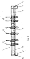
- Fig. 3 is shown an apparatus 6 or a machine consisting of three modules, viz. a left end module 7, a right end module 9 and an intermediate module 8.
- Each module 7, 8, 9 is here provided with two welding stations 13.
- the welding stations 13 arranged closest to the ends of the apparatus 6 are adjustable in the longitudinal direction of the apparatus so that the distance from said welding stations 13 to the ends of the apparatus can be varied.
- the length of the cantilevered ends of the reinforcing rods 4 outside the supporting bands by the sides of the rolling net 3 can be varied.
- a gear box 11 with gear wheels 12 for driving the rolling-up of the rod mesh 3.
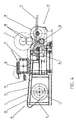
- Fig. 4 shows in the left side of the welding station 13 a supply band roll 1 for a steel supporting band 2.
- the steel supporting band can be rolled up to and along a welding table 14 and forwardly to a rod mesh rolling-up device 22.
- Above the welding stations 13 is arranged a supporting beam 17 with a material shelf 16 on which a bundle of reinforcing rods 4 can be arranged.
- a number of rods therefrom can be arranged in a tray 15 immediately above the welding table 14.
- the welding of reinforcement rod 4 to steel supporting bands 2 takes place by a number of reinforcement rods 4 being arranged on and being welded to the steel supporting band 2 which is arranged on the rail 20 on the welding table 14. Thereafter the steel supporting band 2 is pulled one step forward and the welding can continue or the rolling-up of the rod mesh can be stopped.
- the net rolling device 22 is seen in the left side of Fig. 4 .
- the device consists of a driving ring 18 being driven via a shaft from the gear wheel 12 and on which an outermost reinforcing rod 4 being welded to the rod mesh on the steel supporting band 2 has been hooked, and around which the steel supporting band 2 with welded reinforcement rods 4 has been rolled up.
- the drive unit 18 can follow upwardly when the rolling-up proceeds to a fully rolled up rod mesh 3.
- the driving ring 18 is supported via the rod mesh 3 by a supporting means 19 following the periphery of the rod mesh 3, said supporting means consisting of two vehicle rubber wheels 19 supporting the driving ring 18 during its rotation via the rod mesh 3 being rolled up.
- a chain wheel 23 with friction hub which is driven via a shaft from the gear wheel 12 might bring the vehicle rubber wheel 19 closest to the supply band roll 1 to rotation clockwise and may thus contribute to the rod mesh 3 being tightly rolled up.
- a discharge slide 21 has been provided, along which the finished rod mesh 3 can slide or roll downwardly when the following supporting means 19 is tilted or lowered.
- Fig. 5 shows an exchange- or replaceable operating lever 32 which can be arranged beside, parallel with and somewhat below the rail 20 of each welding table 14, and which is rotatable about 90° around its axis. It is equipped with a number of parallel and perpendicularly to the operating lever 32 arranged stop pins 33 at a mutual distance corresponding to a desired distance between reinforcing rods 4 arranged longitudinally to the rod mesh 3 and being arranged with the operating lever 32 between its vertical and horisontal position.
- Fig. 6 shows a driving ring 18 with a square hub key hole 34, the square of which is a little larger than the cross section of the tubular driving shaft.
- a hook 35 On the periphery of the driving ring 18 there may be arranged a hook 35 on which a reinforcement rod 4 on the rod mesh 3 can be hooked whereafter the tight rolling-up of the rod mesh 3 can be started.
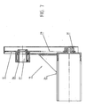
- Fig. 7 shows an axial section of the driving motor 24 of the gear boxes 11, said motor driving a friction hub 31.
- a chain drive 29 therefrom is driving a gear wheel 12 arranged on a hollow shaft 26 with a square drive key hole 27 through which a tubular driving shaft 28 for a driving ring 18 and having a square cross section can be inserted, cf. Fig. 9 .
- Fig. 8 shows the friction hub 31 of the gear box 11, the chain drive 19, gear wheel 12 and hollow shaft 26.
- Fig. 9 shows a tubular driving shaft 28 with tubular cross section which is somewhat smaller than the cross section of the driving key hole 27 in a gear wheel and the cross section of the hub key hole 34 in a driving ring 18.
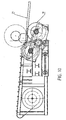
- Fig. 10 shows the welding station 13 with a tilted down supporting means 19 for delivering a finished rod mesh to the discharge slide 21.
Landscapes
- Engineering & Computer Science (AREA)
- Mechanical Engineering (AREA)
- Wire Processing (AREA)
- Reinforcement Elements For Buildings (AREA)
- Rolling Contact Bearings (AREA)
Claims (10)
- Verfahren zum Handhaben einschließlich Aufrollen eines Betonverstärkungs-Stabgitters (3) während seiner Herstellung, wobei das Stabgitter (3) in seiner Längsrichtung sich erstreckende Unterstützungsbänder (2) aus biegsamem Stahl und in seiner Breitenrichtung sich erstreckende Verstärkungsstäbe (4), die vorzugsweise durch Schweißen an den Stahlunterstützungsbändern (2) befestigt sind, umfasst, wobei das Stabgitter (3) in Längsrichtung der Stahlunterstützungsbänder zu einer Stabgitter-Aufrollvorrichtung (22) befördert wird, dadurch gekennzeichnet, dass die beförderten Enden der Stahlunterstützungsbänder (2) - nachdem das Stabgitter (3) zu der Stabgitter-Aufrollvorrichtung (22) befördert worden ist - jeweils an einem von wenigstens zwei Antriebsringen (18) befestigt wird und die Vorrichtung (22) synchron einer tangentialen Zugkraft in Umfangsrichtung der Antriebsringe (18) ausgesetzt wird, dass die Antriebsringe (18) praktisch koaxial als interne Antriebseinheit für das Stabgitter (3) angeordnet sind und einen Außendurchmesser besitzen, der dem gewünschten Innendurchmesser des Stabgitters (3) entspricht, und dass jeder Antriebsring (18) durch ein bewegliches Unterstützungsmittel (19) unterstützt ist, das dem radial äußeren Umfang des Stabgitters (3) synchron folgt, wobei das Unterstützungsmittel (19) den Antriebsring (18) während seiner Drehung über das Stabgitter (3), das aufgerollt wird, unterstützt.
- Verfahren nach Anspruch 1, dadurch gekennzeichnet, dass die Unterstützung mittels des beweglichen Unterstützungsmittels (19) der Antriebsringe (18) mittels eines Paars axial paralleler Unterstützungsräder wie etwa Fahrzeuggummiräder, die in einem gegenseitigen Abstand angeordnet sind, erfolgt.
- Verfahren nach Anspruch 1, dadurch gekennzeichnet, dass die äußersten Stahlunterstützungsbänder (2) für die Herstellung des Stabgitters (3) jeweils durch eine kombinierte Bandbeförderungs- und Schweißstation (13) unterstützt sind, die in Breitenrichtung des Stabgitters verlagerbar angeordnet ist.
- Verfahren nach einem der Ansprüche 1-3, dadurch gekennzeichnet, dass die Drehung der Stabgitter-Aufrollvorrichtung (22) bei jedem Drehstopp während der Herstellung des Stabgitters (3) verriegelt wird.
- Verfahren nach einem der Ansprüche 1-4, dadurch gekennzeichnet, dass nach dem Aufrollen eines beispielsweise mittels eines Bindedrahts von selbst starr verriegelten Stabgitters das Stabgitter, das auf den Unterstützungsrädern (19) ruht, abgesenkt wird, indem diese abgesenkt werden, bis das Stabgitter (3) ausgegeben wird, damit es auf wenigstens zwei von der Schweißstation (13) entfernten nach unten geneigten Ausgabegleitern hinab rollt oder hinab gleitet, um weiterhin an ein Förderband, auf einen Lastkraftwagen, in einen Behälter oder zu einem Aufbewahrungsort ausgegeben zu werden.
- Vorrichtung für die Verwendung durch Handhabung einschließlich Aufrollen eines Stabgitters (3) während der Herstellung des Stabgitters, wobei das Stabgitter (3) in seiner Längsrichtung sich erstreckende Stahlunterstützungsbänder (2) und in seiner Breitenrichtung sich erstreckende Verstärkungsstäbe (4), die vorzugsweise durch Schweißen an den Stahlunterstützungsbändern (2) befestigt sind, umfasst, wobei das Stabgitter (3) in Längsrichtung der Stahlunterstützungsbänder zu einer Stabgitter-Aufrollvorrichtung (22) befördert wird, dadurch gekennzeichnet, dass die Stabgitter-Aufrollvorrichtung (22) - nachdem die beförderten Enden der Stahlunterstützungsbänder (2) zu der Stabgitter-Aufrollvorrichtung (22) befördert worden sind - dazu ausgelegt ist, die Stahlunterstützungsbänder (2) des Stabgitters (3) synchron einer Zugkraft in Umfangsrichtung von wenigstens zwei Antriebsringen (18) auszusetzen, dass die Antriebsringe (18) praktisch koaxial als interne Antriebseinheit für das Stabgitter (3) angeordnet sind und einen Außendurchmesser haben, der dem gewünschten Innendurchmesser des Stabgitters (3) entspricht, und dass jeder Antriebsring (18) durch ein bewegliches Unterstützungsmittel (19), das dem radial äußeren Umfang des Stabgitters (3) synchron folgt, etwa ein Paar axial paralleler Unterstützungsräder, z. B. Fahrzeugräder, die in einem gegenseitigen Abstand angeordnet sind, unterstützt ist, wobei das Unterstützungsmittel (19) seinen jeweiligen Antriebsring (18) während seiner Drehung über das Stabgitter (3), das aufgerollt wird, unterstützt.
- Vorrichtung nach Anspruch 6, dadurch gekennzeichnet, dass sie (6) aus einem oder mehreren Modulen (7-9) besteht, die nebeneinander in Längsrichtung der Vorrichtung (6) angeordnet sind, wobei jedes Modul wenigstens eine, vorzugsweise zwei montierte Schweißstationen (13) besitzt, wovon jede eine entsprechende Zufuhrbandrolle mit einem Stahlunterstützungsband (2) und wenigstens eine Stabgitter-Aufrollvorrichtung (22) mit einer integrierten Zugvorrichtung, die so angeordnet und ausgelegt ist, dass eine Zugkraft zum Aufrollen der Stahlunterstützungsbänder (2) übertragen wird und dass die Zugkraft während einer unterdessen auftretenden Unterbrechung des Aufrollens aufrechterhalten werden kann, besitzt.
- Vorrichtung nach Anspruch 7, dadurch gekennzeichnet, dass sie aus wenigstens zwei Endmodulen (7) und (9) besteht, wobei die rechte Schweißstation (13) an dem einen Endmodul (9) und die linke Schweißstation (13) an dem zweiten Endmodul (7) einstellbar sind, so dass der Abstand zwischen den Schweißstationen (13) in den jeweiligen Endmodulen (7) und (9) verändert werden kann.
- Vorrichtung nach einem der Ansprüche 6-7, wobei die Schweißstation (13) einen Schweißtisch (14) mit einer Schiene (20) aus einem Material mit einer verhältnismäßig hohen spezifischen Wärmekapazität besitzt, wobei die Schiene so angeordnet ist, dass das Stahlunterstützungsband (2) auf der Schiene auf seinem Weg von der Zufuhrbandrolle (1) zu der Stabgitter-Aufrollvorrichtung (22) gleiten kann, dadurch gekennzeichnet, dass in der Nähe der Schiene (20) jedes Schweißtisches (14), parallel hierzu und etwas unterhalb hiervon ein austauschbar angeordneter Bedienungshebel (32) angeordnet ist, der um seine Achse um etwa 90° drehbar ist, wobei der Bedienungshebel mit einer Anzahl paralleler Anschlagstifte senkrecht zu dem Bedienungshebel (32) versehen ist, die in einem gegenseitigen Abstand angeordnet sind, der einem gewünschten Abstand zwischen den Verstärkungsstäben (4) eines Stabgitters (3) entspricht, die in Längsrichtung des Stabgitters (3) angeordnet sind, und mittels des Bedienungshebels (32) zwischen einer vertikalen und einer horizontalen Stellung drehbar sind.
- Vorrichtung nach einem der Ansprüche 6-9, dadurch gekennzeichnet, dass sie eine oder zwei rohrförmige Antriebswellen (28) mit quadratischem Querschnitt, die in ihrer Längsrichtung verlagerbar sind, besitzt, wobei die Antriebswellen durch Getriebe (11) angetrieben werden, die an dem einen Ende bzw. an beiden Enden der Vorrichtung (6) angeordnet sind, wobei die Getriebe mit Zahnrädern versehen sind, die Hohlwellen besitzen, die antreibende Keillöcher (27) mit quadratischem Querschnitt aufweisen, wobei die Seite des Quadrats etwas größer als die Querschnittsseiten der Antriebswellen (28) ist, wobei die Antriebsringe (18) Hohlnaben besitzen und ebenfalls mit antreibenden Keillöchern (27) mit quadratischem Querschnitt versehen sind, wobei die Seite des Quadrats etwas größer ist als die Querschnittsseiten der Antriebswelle (28).
Applications Claiming Priority (3)
| Application Number | Priority Date | Filing Date | Title |
|---|---|---|---|
| DK200200977A DK176858B1 (da) | 2002-06-25 | 2002-06-25 | Fremgangsmåde og apparat til håndtering af rullenet |
| DK200200977 | 2002-06-25 | ||
| PCT/DK2003/000421 WO2004000483A1 (en) | 2002-06-25 | 2003-06-21 | Method and apparatus for the handling, including rolling-up of rod mesh for concrete reinforcement |
Publications (2)
| Publication Number | Publication Date |
|---|---|
| EP1515811A1 EP1515811A1 (de) | 2005-03-23 |
| EP1515811B1 true EP1515811B1 (de) | 2009-03-25 |
Family
ID=29797011
Family Applications (1)
| Application Number | Title | Priority Date | Filing Date |
|---|---|---|---|
| EP03729913A Expired - Lifetime EP1515811B1 (de) | 2002-06-25 | 2003-06-21 | Verfahren und vorrichtung zum handhaben, einschliesslich aufrollen, von stangengitter für betonbewehrung |
Country Status (6)
| Country | Link |
|---|---|
| EP (1) | EP1515811B1 (de) |
| AT (1) | ATE426473T1 (de) |
| AU (1) | AU2003242234A1 (de) |
| DE (1) | DE60326842D1 (de) |
| DK (1) | DK176858B1 (de) |
| WO (1) | WO2004000483A1 (de) |
Families Citing this family (1)
| Publication number | Priority date | Publication date | Assignee | Title |
|---|---|---|---|---|
| JP4531632B2 (ja) * | 2005-05-30 | 2010-08-25 | 日本電信電話株式会社 | 生体成分濃度測定装置及び生体成分濃度測定装置の制御方法 |
Family Cites Families (3)
| Publication number | Priority date | Publication date | Assignee | Title |
|---|---|---|---|---|
| DE9412405U1 (de) * | 1994-04-13 | 1995-08-10 | Häussler, Wilhelm, Dipl.-Ing. Dipl.-Kaufm., 87629 Füssen | Bewehrungsmatte für Stahlbeton-Flächentragwerke sowie Maschine zu deren Herstellung |
| DE9421500U1 (de) * | 1994-04-13 | 1996-01-04 | Häussler, Wilhelm, Dipl.-Ing. Dipl.-Kaufm., 87629 Füssen | Maschinenanlage zur Fertigung von Bewehrungsmatten für Stahlbeton-Flächentragwerke und diese Bewehrungsmatten selbst |
| DE19752515A1 (de) * | 1997-11-27 | 1999-06-02 | Haeussler Planung Gmbh | Verfahren und Maschine zur Herstellung von aufgerollten Bewehrungsstabmatten |
-
2002
- 2002-06-25 DK DK200200977A patent/DK176858B1/da not_active IP Right Cessation
-
2003
- 2003-06-21 WO PCT/DK2003/000421 patent/WO2004000483A1/en not_active Ceased
- 2003-06-21 DE DE60326842T patent/DE60326842D1/de not_active Expired - Lifetime
- 2003-06-21 EP EP03729913A patent/EP1515811B1/de not_active Expired - Lifetime
- 2003-06-21 AU AU2003242234A patent/AU2003242234A1/en not_active Abandoned
- 2003-06-21 AT AT03729913T patent/ATE426473T1/de not_active IP Right Cessation
Also Published As
| Publication number | Publication date |
|---|---|
| EP1515811A1 (de) | 2005-03-23 |
| DK176858B1 (da) | 2010-01-04 |
| DK200200977A (da) | 2003-12-26 |
| AU2003242234A1 (en) | 2004-01-06 |
| WO2004000483A1 (en) | 2003-12-31 |
| ATE426473T1 (de) | 2009-04-15 |
| DE60326842D1 (de) | 2009-05-07 |
Similar Documents
| Publication | Publication Date | Title |
|---|---|---|
| KR100761088B1 (ko) | 이중파형강관 제조장치 | |
| CN108941395B (zh) | 一种集成化钢筋笼成型机器人 | |
| JP5356664B2 (ja) | 鉄筋の自動結束方法及び装置 | |
| EP2938483B1 (de) | Verfahren zum bewerkstelligen der kontinuierlichen zuführung eines länglichen elements zu einer reifenherstellungsstation und abwicklungsvorrichtung | |
| EP1364726B1 (de) | Vorrichtung zur Herstellung von Bewehrungskäfigen | |
| US6000261A (en) | Method and apparatus for portable spiral pipe manufacturing | |
| EP1332010B1 (de) | Vorrichtung zur herstellung von verstärkungskäfigen für stahlbeton | |
| CN117737385A (zh) | 一种用于炉管热处理的上料装置 | |
| CN113695495A (zh) | 一种钢筋笼箍筋绑扎设备 | |
| JP6302571B2 (ja) | ストリップ材料を巻くための装置及び方法 | |
| CN101992928A (zh) | 输送带装置 | |
| KR100836678B1 (ko) | 슬리브 자동이송장치 | |
| CN110550481A (zh) | 拉伸塑料土工格栅自动收卷卸卷机及其使用方法 | |
| CN207668871U (zh) | 钢板横剪生产线 | |
| EP1515811A1 (de) | Verfahren und vorrichtung zum handhaben, einschliesslich aufrollen, von stangengitter für betonbewehrung | |
| AU722830B2 (en) | An apparatus for making reinforcing cages for reinforcing concrete | |
| CN107470916A (zh) | 钢板横剪生产线及应用其的钢板横剪工艺 | |
| CN118451902A (zh) | 一种适用于仿地行走的青稞收割打捆一体化装备 | |
| CN206606815U (zh) | 一种分卷机上料装置 | |
| CN220244480U (zh) | 一种金属管自动卸料设备 | |
| CN217703842U (zh) | 翻转布料一体成型式烟道成型设备 | |
| TW201332710A (zh) | 具有前端或前後驅動系統的旋轉進入系統 | |
| CN201660688U (zh) | 一种铜管退火炉的自动卸料装置 | |
| JP2008308294A (ja) | 帯状部材結束体の施工装置 | |
| CN216583286U (zh) | 开卷机用送料车 |
Legal Events
| Date | Code | Title | Description |
|---|---|---|---|
| PUAI | Public reference made under article 153(3) epc to a published international application that has entered the european phase |
Free format text: ORIGINAL CODE: 0009012 |
|
| 17P | Request for examination filed |
Effective date: 20041222 |
|
| AK | Designated contracting states |
Kind code of ref document: A1 Designated state(s): AT BE BG CH CY CZ DE DK EE ES FI FR GB GR HU IE IT LI LU MC NL PT RO SE SI SK TR |
|
| AX | Request for extension of the european patent |
Extension state: AL LT LV MK |
|
| DAX | Request for extension of the european patent (deleted) | ||
| GRAP | Despatch of communication of intention to grant a patent |
Free format text: ORIGINAL CODE: EPIDOSNIGR1 |
|
| GRAS | Grant fee paid |
Free format text: ORIGINAL CODE: EPIDOSNIGR3 |
|
| GRAA | (expected) grant |
Free format text: ORIGINAL CODE: 0009210 |
|
| AK | Designated contracting states |
Kind code of ref document: B1 Designated state(s): AT BE BG CH CY CZ DE DK EE ES FI FR GB GR HU IE IT LI LU MC NL PT RO SE SI SK TR |
|
| REG | Reference to a national code |
Ref country code: GB Ref legal event code: FG4D |
|
| REG | Reference to a national code |
Ref country code: CH Ref legal event code: EP |
|
| REG | Reference to a national code |
Ref country code: IE Ref legal event code: FG4D |
|
| REF | Corresponds to: |
Ref document number: 60326842 Country of ref document: DE Date of ref document: 20090507 Kind code of ref document: P |
|
| PG25 | Lapsed in a contracting state [announced via postgrant information from national office to epo] |
Ref country code: SI Free format text: LAPSE BECAUSE OF FAILURE TO SUBMIT A TRANSLATION OF THE DESCRIPTION OR TO PAY THE FEE WITHIN THE PRESCRIBED TIME-LIMIT Effective date: 20090325 Ref country code: FI Free format text: LAPSE BECAUSE OF FAILURE TO SUBMIT A TRANSLATION OF THE DESCRIPTION OR TO PAY THE FEE WITHIN THE PRESCRIBED TIME-LIMIT Effective date: 20090325 |
|
| PG25 | Lapsed in a contracting state [announced via postgrant information from national office to epo] |
Ref country code: SE Free format text: LAPSE BECAUSE OF FAILURE TO SUBMIT A TRANSLATION OF THE DESCRIPTION OR TO PAY THE FEE WITHIN THE PRESCRIBED TIME-LIMIT Effective date: 20090625 |
|
| NLV1 | Nl: lapsed or annulled due to failure to fulfill the requirements of art. 29p and 29m of the patents act | ||
| PG25 | Lapsed in a contracting state [announced via postgrant information from national office to epo] |
Ref country code: BE Free format text: LAPSE BECAUSE OF FAILURE TO SUBMIT A TRANSLATION OF THE DESCRIPTION OR TO PAY THE FEE WITHIN THE PRESCRIBED TIME-LIMIT Effective date: 20090325 |
|
| PG25 | Lapsed in a contracting state [announced via postgrant information from national office to epo] |
Ref country code: PT Free format text: LAPSE BECAUSE OF FAILURE TO SUBMIT A TRANSLATION OF THE DESCRIPTION OR TO PAY THE FEE WITHIN THE PRESCRIBED TIME-LIMIT Effective date: 20090901 Ref country code: CZ Free format text: LAPSE BECAUSE OF FAILURE TO SUBMIT A TRANSLATION OF THE DESCRIPTION OR TO PAY THE FEE WITHIN THE PRESCRIBED TIME-LIMIT Effective date: 20090325 Ref country code: ES Free format text: LAPSE BECAUSE OF FAILURE TO SUBMIT A TRANSLATION OF THE DESCRIPTION OR TO PAY THE FEE WITHIN THE PRESCRIBED TIME-LIMIT Effective date: 20090706 Ref country code: EE Free format text: LAPSE BECAUSE OF FAILURE TO SUBMIT A TRANSLATION OF THE DESCRIPTION OR TO PAY THE FEE WITHIN THE PRESCRIBED TIME-LIMIT Effective date: 20090325 |
|
| PG25 | Lapsed in a contracting state [announced via postgrant information from national office to epo] |
Ref country code: RO Free format text: LAPSE BECAUSE OF FAILURE TO SUBMIT A TRANSLATION OF THE DESCRIPTION OR TO PAY THE FEE WITHIN THE PRESCRIBED TIME-LIMIT Effective date: 20090325 Ref country code: NL Free format text: LAPSE BECAUSE OF FAILURE TO SUBMIT A TRANSLATION OF THE DESCRIPTION OR TO PAY THE FEE WITHIN THE PRESCRIBED TIME-LIMIT Effective date: 20090325 Ref country code: SK Free format text: LAPSE BECAUSE OF FAILURE TO SUBMIT A TRANSLATION OF THE DESCRIPTION OR TO PAY THE FEE WITHIN THE PRESCRIBED TIME-LIMIT Effective date: 20090325 |
|
| PG25 | Lapsed in a contracting state [announced via postgrant information from national office to epo] |
Ref country code: BG Free format text: LAPSE BECAUSE OF FAILURE TO SUBMIT A TRANSLATION OF THE DESCRIPTION OR TO PAY THE FEE WITHIN THE PRESCRIBED TIME-LIMIT Effective date: 20090625 Ref country code: DK Free format text: LAPSE BECAUSE OF FAILURE TO SUBMIT A TRANSLATION OF THE DESCRIPTION OR TO PAY THE FEE WITHIN THE PRESCRIBED TIME-LIMIT Effective date: 20090325 Ref country code: MC Free format text: LAPSE BECAUSE OF NON-PAYMENT OF DUE FEES Effective date: 20090630 |
|
| PLBE | No opposition filed within time limit |
Free format text: ORIGINAL CODE: 0009261 |
|
| REG | Reference to a national code |
Ref country code: CH Ref legal event code: PL |
|
| STAA | Information on the status of an ep patent application or granted ep patent |
Free format text: STATUS: NO OPPOSITION FILED WITHIN TIME LIMIT |
|
| 26N | No opposition filed |
Effective date: 20091229 |
|
| REG | Reference to a national code |
Ref country code: FR Ref legal event code: ST Effective date: 20100226 |
|
| REG | Reference to a national code |
Ref country code: IE Ref legal event code: MM4A |
|
| PG25 | Lapsed in a contracting state [announced via postgrant information from national office to epo] |
Ref country code: IE Free format text: LAPSE BECAUSE OF NON-PAYMENT OF DUE FEES Effective date: 20090621 Ref country code: LI Free format text: LAPSE BECAUSE OF NON-PAYMENT OF DUE FEES Effective date: 20090630 Ref country code: FR Free format text: LAPSE BECAUSE OF NON-PAYMENT OF DUE FEES Effective date: 20090630 Ref country code: CH Free format text: LAPSE BECAUSE OF NON-PAYMENT OF DUE FEES Effective date: 20090630 |
|
| PGFP | Annual fee paid to national office [announced via postgrant information from national office to epo] |
Ref country code: AT Payment date: 20100615 Year of fee payment: 8 Ref country code: IT Payment date: 20100618 Year of fee payment: 8 |
|
| PG25 | Lapsed in a contracting state [announced via postgrant information from national office to epo] |
Ref country code: GR Free format text: LAPSE BECAUSE OF FAILURE TO SUBMIT A TRANSLATION OF THE DESCRIPTION OR TO PAY THE FEE WITHIN THE PRESCRIBED TIME-LIMIT Effective date: 20090626 |
|
| PGFP | Annual fee paid to national office [announced via postgrant information from national office to epo] |
Ref country code: DE Payment date: 20100617 Year of fee payment: 8 Ref country code: GB Payment date: 20100614 Year of fee payment: 8 |
|
| PG25 | Lapsed in a contracting state [announced via postgrant information from national office to epo] |
Ref country code: LU Free format text: LAPSE BECAUSE OF NON-PAYMENT OF DUE FEES Effective date: 20090621 |
|
| PG25 | Lapsed in a contracting state [announced via postgrant information from national office to epo] |
Ref country code: HU Free format text: LAPSE BECAUSE OF FAILURE TO SUBMIT A TRANSLATION OF THE DESCRIPTION OR TO PAY THE FEE WITHIN THE PRESCRIBED TIME-LIMIT Effective date: 20090926 |
|
| PG25 | Lapsed in a contracting state [announced via postgrant information from national office to epo] |
Ref country code: TR Free format text: LAPSE BECAUSE OF FAILURE TO SUBMIT A TRANSLATION OF THE DESCRIPTION OR TO PAY THE FEE WITHIN THE PRESCRIBED TIME-LIMIT Effective date: 20090325 |
|
| PG25 | Lapsed in a contracting state [announced via postgrant information from national office to epo] |
Ref country code: CY Free format text: LAPSE BECAUSE OF FAILURE TO SUBMIT A TRANSLATION OF THE DESCRIPTION OR TO PAY THE FEE WITHIN THE PRESCRIBED TIME-LIMIT Effective date: 20090325 |
|
| GBPC | Gb: european patent ceased through non-payment of renewal fee |
Effective date: 20110621 |
|
| PG25 | Lapsed in a contracting state [announced via postgrant information from national office to epo] |
Ref country code: IT Free format text: LAPSE BECAUSE OF NON-PAYMENT OF DUE FEES Effective date: 20110621 Ref country code: AT Free format text: LAPSE BECAUSE OF NON-PAYMENT OF DUE FEES Effective date: 20110621 |
|
| REG | Reference to a national code |
Ref country code: AT Ref legal event code: MM01 Ref document number: 426473 Country of ref document: AT Kind code of ref document: T Effective date: 20110621 |
|
| REG | Reference to a national code |
Ref country code: DE Ref legal event code: R119 Ref document number: 60326842 Country of ref document: DE Effective date: 20120103 |
|
| PG25 | Lapsed in a contracting state [announced via postgrant information from national office to epo] |
Ref country code: DE Free format text: LAPSE BECAUSE OF NON-PAYMENT OF DUE FEES Effective date: 20120103 |
|
| PG25 | Lapsed in a contracting state [announced via postgrant information from national office to epo] |
Ref country code: GB Free format text: LAPSE BECAUSE OF NON-PAYMENT OF DUE FEES Effective date: 20110621 |