EP1515419A2 - Méthode de magnétisation d'éléments magnétiques pour une machine électrique - Google Patents
Méthode de magnétisation d'éléments magnétiques pour une machine électrique Download PDFInfo
- Publication number
- EP1515419A2 EP1515419A2 EP04012970A EP04012970A EP1515419A2 EP 1515419 A2 EP1515419 A2 EP 1515419A2 EP 04012970 A EP04012970 A EP 04012970A EP 04012970 A EP04012970 A EP 04012970A EP 1515419 A2 EP1515419 A2 EP 1515419A2
- Authority
- EP
- European Patent Office
- Prior art keywords
- magnet element
- sensor magnet
- working
- electric machine
- sensor
- Prior art date
- Legal status (The legal status is an assumption and is not a legal conclusion. Google has not performed a legal analysis and makes no representation as to the accuracy of the status listed.)
- Withdrawn
Links
Images
Classifications
-
- H—ELECTRICITY
- H02—GENERATION; CONVERSION OR DISTRIBUTION OF ELECTRIC POWER
- H02K—DYNAMO-ELECTRIC MACHINES
- H02K15/00—Processes or apparatus specially adapted for manufacturing, assembling, maintaining or repairing of dynamo-electric machines
- H02K15/02—Processes or apparatus specially adapted for manufacturing, assembling, maintaining or repairing of dynamo-electric machines of stator or rotor bodies
- H02K15/03—Processes or apparatus specially adapted for manufacturing, assembling, maintaining or repairing of dynamo-electric machines of stator or rotor bodies having permanent magnets
-
- H—ELECTRICITY
- H02—GENERATION; CONVERSION OR DISTRIBUTION OF ELECTRIC POWER
- H02K—DYNAMO-ELECTRIC MACHINES
- H02K21/00—Synchronous motors having permanent magnets; Synchronous generators having permanent magnets
- H02K21/12—Synchronous motors having permanent magnets; Synchronous generators having permanent magnets with stationary armatures and rotating magnets
- H02K21/14—Synchronous motors having permanent magnets; Synchronous generators having permanent magnets with stationary armatures and rotating magnets with magnets rotating within the armatures
Definitions
- the present invention relates to a method for Magnetization of magnetic elements for an electronic commutated electric machine, such as e.g. an EC motor or EC generator. Furthermore, the invention relates to a electrical machine comprising magnetic elements, which according to were magnetized according to the method of the invention.
- Permanently energized EC motors or EC generators are used in used more recently.
- Such EC machines are often designed such that on a rotor shaft a working magnet element and a sensor magnet element is arranged. This is so far on the rotor shaft assembled working magnet element together with the rotor shaft magnetized.
- the sensor magnet element is usually a plastic-bonded magnet that already works before mounting was magnetized separately.
- the two Magnetic elements mounted on a rotor shaft Before the final fixation of the two magnetic elements on the Rotor shaft, however, need expensive adjustment operations be executed to the two magnetic elements to each other align to the electric machine with a high To operate efficiency.
- the Pole divisions of the working magnetic element with the pole pitches match the sensor magnet element.
- twelve-pole EC electrical machines used have already smallest tolerance deviations a big negative impact on overall efficiency. Therefore, in the production of EC machines is also a elaborate quality assurance necessary.
- the working magnetic element and the Magnetic sensor unmagnetized on a component of the electrical machine mounted and the two magnetic elements then be in their final mounting position simultaneously magnetized.
- the component of the electric machine, on which is the working magnetic element and the sensor magnetic element be mounted before their magnetization, the rotor shaft.
- the sensor magnet element and / or contains the working magnetic element as magnetizable components a rare earth material or the magnetizable parts of the sensor magnet element are made entirely of ferrite produced.
- this magnetic material is included embedded in a plastic.
- Neodymium-iron-boron (NdFeB) is particularly preferred as magnetizable material used.
- the magnetization of the sensor magnet element and the Working magnet element is preferably oriented radially or circularly executed. Especially at the Radial magnetization becomes a magnetizing one Return ring used, in particular, the Rotor shaft used for a magnetic return can be. Another method of magnetization is the so-called Hallbach magnetization for a circular Orientation of the magnetic elements
- anisotropic magnets In the production of anisotropic magnets, the course of the Imprinted field lines. That means that when anisotropic Magnets the Fe or the NdFeB particles the field course be preceded accordingly. This allows radial and circular particle orientations be embossed. Will the particles become anisotropic (aligned) as opposed to isotropic (unaligned) integrated, the field strength increases by up to approx. 40% as with the isotropic magnets.
- the material for the sensor magnet element e.g. an isotropic one plastic-bonded magnet from NdFeB a larger Field strength as a plastic-bound magnet with Fe. Due to the higher remanence is the plastic bound Magnet made of NdFrB as sensor magnet element still suitable.
- An anisotropic, plastic-bonded Magnetic element of Fe is contrary to the isotropic conditional by the higher remanence for the present application nevertheless suitable.
- the sensor magnet element made of Fe clear cheaper than one with NdFeB, is preferred a sensor magnet element with plastic-bound Iron materials used.
- the present invention relates to a electric machine with a working magnetic element and a sensor magnet element, which according to one of the above at the same time in their final assembly position were manufactured.
- the inventive electrical Machine is in particular as EC motor or EC generator trained and used in vehicles, especially as EC engine for driving comfort devices of the vehicle, such as. electric windows, electric Sunroofs, electric seat adjustment, etc. or as Wiper motor, used.
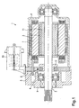
- FIG. 1 shows a sectional view of an electrical Machine (1), which uses magnetic elements according to the inventive method were magnetized.
- the Electric machine (1) is an electronically commutated Motor comprising a rotor shaft (2) and a stator (7) includes.
- the stator is arranged in a pole pot (8) and an open end of the pole pot is through a bearing plate (9) covered in a known manner.
- the rotor shaft (2) is stored on the one hand at the end of the pole pot (8) and on the other hand, on the bearing plate (9).
- a working magnetic element (3) is arranged, which is formed substantially hollow cylindrical, wherein between the working magnetic element (3) and the rotor shaft (2) a return ring (11) is arranged.
- the position of the working magnetic element (3) being able to determine is still on the rotor shaft (2) a sensor magnet element (4), which by means of a sensor (5) is scanned.
- the sensor (5) is in a sensor carrier (6) attached.
- a plug (10) provided for a power supply of the EC motor.
- the electric machine (1) has now been manufactured in such a way in a first step, the working magnetic element (3) with the return ring (11) mounted on the rotor shaft (2) was and also the sensor magnet element (4) on the Rotor shaft (2) was mounted. As shown in Figure 1, is the sensor magnet element (4) also annular and is via a return element (12) on the rotor shaft (2) attached.
- the working magnetic element (3) and the sensor magnet element (4) each in unmagnetized Way mounted on the rotor shaft (2).
- the sensor magnet element (4) is made of a manufactured plastic-bonded material. That is more accurate Sensor magnet element (4) as a plastic-bonded magnet with NdFeB or Fe-magnetizing proportions. Due to its material composition has the Sensor magnet element (4) thus considerably lower Field strengths as the working magnetic element (3).
- the two Magnetic elements (3, 4) magnetized together. This is preferably carried out a radial magnetization, wherein For example, the rotor shaft (2) as a return element acts. It turned out that at one radial magnetization of the two magnetic elements (3, 4) the lowest sources of error occur. Because of the common Magnetization of working magnet element (3) and Sensor magnet element (4) can be applied to those in the prior art necessary fine adjustment of the two magnetic elements to dispense with each other. This allows the inventive electric machine clearly cheaper and produced in shorter time become. Furthermore, in the assembly of the two Magnetic elements no reference assignment to the rotor shaft necessary to indicate the pole pitch of the magnetic elements to keep defined locations relative to the rotor shaft.
- an electric machine (1) obtained which compared with the prior art a significantly better efficiency at lower Has manufacturing costs.
- Through the common magnetization of the two magnetic elements (3, 4) can continue a Consistently high quality in the production of electrical machine to be ensured.
Landscapes
- Engineering & Computer Science (AREA)
- Manufacturing & Machinery (AREA)
- Power Engineering (AREA)
- Permanent Field Magnets Of Synchronous Machinery (AREA)
Applications Claiming Priority (2)
| Application Number | Priority Date | Filing Date | Title |
|---|---|---|---|
| DE10340939 | 2003-09-05 | ||
| DE2003140939 DE10340939A1 (de) | 2003-09-05 | 2003-09-05 | Verfahren zur Magnetisierung von Magnetelementen für eine elektrische Maschine |
Publications (2)
| Publication Number | Publication Date |
|---|---|
| EP1515419A2 true EP1515419A2 (fr) | 2005-03-16 |
| EP1515419A3 EP1515419A3 (fr) | 2005-11-16 |
Family
ID=34129658
Family Applications (1)
| Application Number | Title | Priority Date | Filing Date |
|---|---|---|---|
| EP04012970A Withdrawn EP1515419A3 (fr) | 2003-09-05 | 2004-06-02 | Méthode de magnétisation d'éléments magnétiques pour une machine électrique |
Country Status (2)
| Country | Link |
|---|---|
| EP (1) | EP1515419A3 (fr) |
| DE (1) | DE10340939A1 (fr) |
Cited By (3)
| Publication number | Priority date | Publication date | Assignee | Title |
|---|---|---|---|---|
| CN102916516A (zh) * | 2011-08-05 | 2013-02-06 | 永济新时速电机电器有限责任公司 | 接线装置、双馈风力发电机转子及发电机 |
| EP3629455A1 (fr) * | 2018-09-28 | 2020-04-01 | Valeo Systèmes d'Essuyage | Procédé de fabrication d'un rotor d'un moteur électrique |
| EP3629456A1 (fr) * | 2018-09-28 | 2020-04-01 | Valeo Systèmes d'Essuyage | Procédé de fabrication d'un rotor d'un moteur électrique |
Family Cites Families (4)
| Publication number | Priority date | Publication date | Assignee | Title |
|---|---|---|---|---|
| US5942824A (en) * | 1997-01-28 | 1999-08-24 | Fuji Xerox Co., Ltd. | Motor and method of manufacturing same |
| US6538403B2 (en) * | 2000-01-07 | 2003-03-25 | Black & Decker Inc. | Brushless DC motor sensor control system and method |
| JP2001309618A (ja) * | 2000-04-20 | 2001-11-02 | Nidec Shibaura Corp | ブラシレスモータ |
| JP3748037B2 (ja) * | 2000-08-30 | 2006-02-22 | 三菱電機株式会社 | ブラシレスモータ及び空気調和機 |
-
2003
- 2003-09-05 DE DE2003140939 patent/DE10340939A1/de not_active Withdrawn
-
2004
- 2004-06-02 EP EP04012970A patent/EP1515419A3/fr not_active Withdrawn
Cited By (4)
| Publication number | Priority date | Publication date | Assignee | Title |
|---|---|---|---|---|
| CN102916516A (zh) * | 2011-08-05 | 2013-02-06 | 永济新时速电机电器有限责任公司 | 接线装置、双馈风力发电机转子及发电机 |
| EP3629455A1 (fr) * | 2018-09-28 | 2020-04-01 | Valeo Systèmes d'Essuyage | Procédé de fabrication d'un rotor d'un moteur électrique |
| EP3629456A1 (fr) * | 2018-09-28 | 2020-04-01 | Valeo Systèmes d'Essuyage | Procédé de fabrication d'un rotor d'un moteur électrique |
| WO2020065017A1 (fr) * | 2018-09-28 | 2020-04-02 | Valeo Systèmes d'Essuyage | Procédé de fabrication d'un rotor d'un moteur électrique |
Also Published As
| Publication number | Publication date |
|---|---|
| EP1515419A3 (fr) | 2005-11-16 |
| DE10340939A1 (de) | 2005-03-31 |
Similar Documents
| Publication | Publication Date | Title |
|---|---|---|
| DE69620284T2 (de) | Elektrische Rotationsmaschine | |
| DE69500829T2 (de) | Gleichstrommotor mit axialem Luftspalt | |
| DE102004017157B4 (de) | Verfahren zur Herstellung einer Rotoranordnung und Rotoranordnung für eine elektrische Maschine | |
| DE102011105867B4 (de) | Rotor für eine elektrische Maschine | |
| DE112010003859T5 (de) | Drehmotor vom Lundell-Typ | |
| EP2991196A2 (fr) | Aimant permanent pour un rotor d'une machine électrique | |
| DE102011101730A1 (de) | Elektromotor | |
| DE102015004554A1 (de) | Rotor und Motor | |
| EP2838180B1 (fr) | Rotor d'une machine rotative dynamoélectrique | |
| EP1969700B1 (fr) | Rotor et machine électrique contenant celui-ci | |
| DE102016214838A1 (de) | Ermitteln einer Drehrichtung eines Läufers einer rotierenden elektrischen Maschine | |
| DE102004014985A1 (de) | Rotoranordnung für einen Elektromotor und Verfahren zu deren Herstellung | |
| EP1515419A2 (fr) | Méthode de magnétisation d'éléments magnétiques pour une machine électrique | |
| DE102007061381A1 (de) | Gleichstrommaschine | |
| DE10123513A1 (de) | Elektrische Meßtechnik, speziell Weg- und Winkelaufnehmer mit magnetoresistiven Sensorelementen | |
| DE102009028036A1 (de) | Elektromotor mit Permanentmagnet-Erregung | |
| DE10331960A1 (de) | Ringmagnet | |
| DE102006017233B4 (de) | Rotoranordnung für eine elektrische Maschine und Klauenpolmotor | |
| DE4106484A1 (de) | Buerstenloser gleichstrommotor fuer niedrige drehzahlen | |
| DE102006058064A1 (de) | Elektrische Drehfeldmaschine | |
| DE102014225378A1 (de) | Elektrische Maschine, insbesondere Startermotor für eine Startvorrichtung | |
| DE1261235B (de) | Rotor fuer elektrische Maschinen, insbesondere Synchron-Kleinstmotoren | |
| DE102019122603A1 (de) | Rotorvorrichtung und Statorvorrichtung für einen flachen bürstenlosen elektrischen Motor sowie flacher, bürstenloser elektrischer Motor für ein Dachsystem eines Automobils | |
| DE10056875A1 (de) | Rotor für eine elektrische Maschine | |
| DE19653208B4 (de) | Verfahren zur Herstellung eines permanenterregten niederpoligen Elektromotors mit einem hochpoligen Drehimpuls-Geber |
Legal Events
| Date | Code | Title | Description |
|---|---|---|---|
| PUAI | Public reference made under article 153(3) epc to a published international application that has entered the european phase |
Free format text: ORIGINAL CODE: 0009012 |
|
| AK | Designated contracting states |
Kind code of ref document: A2 Designated state(s): AT BE BG CH CY CZ DE DK EE ES FI FR GB GR HU IE IT LI LU MC NL PL PT RO SE SI SK TR |
|
| AX | Request for extension of the european patent |
Extension state: AL HR LT LV MK |
|
| PUAL | Search report despatched |
Free format text: ORIGINAL CODE: 0009013 |
|
| AK | Designated contracting states |
Kind code of ref document: A3 Designated state(s): AT BE BG CH CY CZ DE DK EE ES FI FR GB GR HU IE IT LI LU MC NL PL PT RO SE SI SK TR |
|
| AX | Request for extension of the european patent |
Extension state: AL HR LT LV MK |
|
| AKX | Designation fees paid | ||
| STAA | Information on the status of an ep patent application or granted ep patent |
Free format text: STATUS: THE APPLICATION IS DEEMED TO BE WITHDRAWN |
|
| 18D | Application deemed to be withdrawn |
Effective date: 20060517 |
|
| REG | Reference to a national code |
Ref country code: DE Ref legal event code: 8566 |