EP1515419A2 - Method for magnetizing magnet elements for an electric machine - Google Patents
Method for magnetizing magnet elements for an electric machine Download PDFInfo
- Publication number
- EP1515419A2 EP1515419A2 EP04012970A EP04012970A EP1515419A2 EP 1515419 A2 EP1515419 A2 EP 1515419A2 EP 04012970 A EP04012970 A EP 04012970A EP 04012970 A EP04012970 A EP 04012970A EP 1515419 A2 EP1515419 A2 EP 1515419A2
- Authority
- EP
- European Patent Office
- Prior art keywords
- magnet element
- sensor magnet
- working
- electric machine
- sensor
- Prior art date
- Legal status (The legal status is an assumption and is not a legal conclusion. Google has not performed a legal analysis and makes no representation as to the accuracy of the status listed.)
- Withdrawn
Links
Images
Classifications
-
- H—ELECTRICITY
- H02—GENERATION; CONVERSION OR DISTRIBUTION OF ELECTRIC POWER
- H02K—DYNAMO-ELECTRIC MACHINES
- H02K15/00—Methods or apparatus specially adapted for manufacturing, assembling, maintaining or repairing of dynamo-electric machines
- H02K15/02—Methods or apparatus specially adapted for manufacturing, assembling, maintaining or repairing of dynamo-electric machines of stator or rotor bodies
- H02K15/03—Methods or apparatus specially adapted for manufacturing, assembling, maintaining or repairing of dynamo-electric machines of stator or rotor bodies having permanent magnets
-
- H—ELECTRICITY
- H02—GENERATION; CONVERSION OR DISTRIBUTION OF ELECTRIC POWER
- H02K—DYNAMO-ELECTRIC MACHINES
- H02K21/00—Synchronous motors having permanent magnets; Synchronous generators having permanent magnets
- H02K21/12—Synchronous motors having permanent magnets; Synchronous generators having permanent magnets with stationary armatures and rotating magnets
- H02K21/14—Synchronous motors having permanent magnets; Synchronous generators having permanent magnets with stationary armatures and rotating magnets with magnets rotating within the armatures
Definitions
- the present invention relates to a method for Magnetization of magnetic elements for an electronic commutated electric machine, such as e.g. an EC motor or EC generator. Furthermore, the invention relates to a electrical machine comprising magnetic elements, which according to were magnetized according to the method of the invention.
- Permanently energized EC motors or EC generators are used in used more recently.
- Such EC machines are often designed such that on a rotor shaft a working magnet element and a sensor magnet element is arranged. This is so far on the rotor shaft assembled working magnet element together with the rotor shaft magnetized.
- the sensor magnet element is usually a plastic-bonded magnet that already works before mounting was magnetized separately.
- the two Magnetic elements mounted on a rotor shaft Before the final fixation of the two magnetic elements on the Rotor shaft, however, need expensive adjustment operations be executed to the two magnetic elements to each other align to the electric machine with a high To operate efficiency.
- the Pole divisions of the working magnetic element with the pole pitches match the sensor magnet element.
- twelve-pole EC electrical machines used have already smallest tolerance deviations a big negative impact on overall efficiency. Therefore, in the production of EC machines is also a elaborate quality assurance necessary.
- the working magnetic element and the Magnetic sensor unmagnetized on a component of the electrical machine mounted and the two magnetic elements then be in their final mounting position simultaneously magnetized.
- the component of the electric machine, on which is the working magnetic element and the sensor magnetic element be mounted before their magnetization, the rotor shaft.
- the sensor magnet element and / or contains the working magnetic element as magnetizable components a rare earth material or the magnetizable parts of the sensor magnet element are made entirely of ferrite produced.
- this magnetic material is included embedded in a plastic.
- Neodymium-iron-boron (NdFeB) is particularly preferred as magnetizable material used.
- the magnetization of the sensor magnet element and the Working magnet element is preferably oriented radially or circularly executed. Especially at the Radial magnetization becomes a magnetizing one Return ring used, in particular, the Rotor shaft used for a magnetic return can be. Another method of magnetization is the so-called Hallbach magnetization for a circular Orientation of the magnetic elements
- anisotropic magnets In the production of anisotropic magnets, the course of the Imprinted field lines. That means that when anisotropic Magnets the Fe or the NdFeB particles the field course be preceded accordingly. This allows radial and circular particle orientations be embossed. Will the particles become anisotropic (aligned) as opposed to isotropic (unaligned) integrated, the field strength increases by up to approx. 40% as with the isotropic magnets.
- the material for the sensor magnet element e.g. an isotropic one plastic-bonded magnet from NdFeB a larger Field strength as a plastic-bound magnet with Fe. Due to the higher remanence is the plastic bound Magnet made of NdFrB as sensor magnet element still suitable.
- An anisotropic, plastic-bonded Magnetic element of Fe is contrary to the isotropic conditional by the higher remanence for the present application nevertheless suitable.
- the sensor magnet element made of Fe clear cheaper than one with NdFeB, is preferred a sensor magnet element with plastic-bound Iron materials used.
- the present invention relates to a electric machine with a working magnetic element and a sensor magnet element, which according to one of the above at the same time in their final assembly position were manufactured.
- the inventive electrical Machine is in particular as EC motor or EC generator trained and used in vehicles, especially as EC engine for driving comfort devices of the vehicle, such as. electric windows, electric Sunroofs, electric seat adjustment, etc. or as Wiper motor, used.
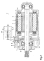
- FIG. 1 shows a sectional view of an electrical Machine (1), which uses magnetic elements according to the inventive method were magnetized.
- the Electric machine (1) is an electronically commutated Motor comprising a rotor shaft (2) and a stator (7) includes.
- the stator is arranged in a pole pot (8) and an open end of the pole pot is through a bearing plate (9) covered in a known manner.
- the rotor shaft (2) is stored on the one hand at the end of the pole pot (8) and on the other hand, on the bearing plate (9).
- a working magnetic element (3) is arranged, which is formed substantially hollow cylindrical, wherein between the working magnetic element (3) and the rotor shaft (2) a return ring (11) is arranged.
- the position of the working magnetic element (3) being able to determine is still on the rotor shaft (2) a sensor magnet element (4), which by means of a sensor (5) is scanned.
- the sensor (5) is in a sensor carrier (6) attached.
- a plug (10) provided for a power supply of the EC motor.
- the electric machine (1) has now been manufactured in such a way in a first step, the working magnetic element (3) with the return ring (11) mounted on the rotor shaft (2) was and also the sensor magnet element (4) on the Rotor shaft (2) was mounted. As shown in Figure 1, is the sensor magnet element (4) also annular and is via a return element (12) on the rotor shaft (2) attached.
- the working magnetic element (3) and the sensor magnet element (4) each in unmagnetized Way mounted on the rotor shaft (2).
- the sensor magnet element (4) is made of a manufactured plastic-bonded material. That is more accurate Sensor magnet element (4) as a plastic-bonded magnet with NdFeB or Fe-magnetizing proportions. Due to its material composition has the Sensor magnet element (4) thus considerably lower Field strengths as the working magnetic element (3).
- the two Magnetic elements (3, 4) magnetized together. This is preferably carried out a radial magnetization, wherein For example, the rotor shaft (2) as a return element acts. It turned out that at one radial magnetization of the two magnetic elements (3, 4) the lowest sources of error occur. Because of the common Magnetization of working magnet element (3) and Sensor magnet element (4) can be applied to those in the prior art necessary fine adjustment of the two magnetic elements to dispense with each other. This allows the inventive electric machine clearly cheaper and produced in shorter time become. Furthermore, in the assembly of the two Magnetic elements no reference assignment to the rotor shaft necessary to indicate the pole pitch of the magnetic elements to keep defined locations relative to the rotor shaft.
- an electric machine (1) obtained which compared with the prior art a significantly better efficiency at lower Has manufacturing costs.
- Through the common magnetization of the two magnetic elements (3, 4) can continue a Consistently high quality in the production of electrical machine to be ensured.
Abstract
Description
Die vorliegende Erfindung betrifft ein Verfahren zur Magnetisierung von Magnetelementen für eine elektronisch kommutierte elektrische Maschine, wie z.B. einen EC-Motor oder EC-Generator. Weiterhin betrifft die Erfindung eine elektrische Maschine, umfassend Magnetelemente, welche gemäß dem erfindungsgemäßen Verfahren magnetisiert wurden.The present invention relates to a method for Magnetization of magnetic elements for an electronic commutated electric machine, such as e.g. an EC motor or EC generator. Furthermore, the invention relates to a electrical machine comprising magnetic elements, which according to were magnetized according to the method of the invention.
Permanent erregte EC-Motoren oder EC-Generatoren werden in jüngster Zeit verstärkt verwendet. Derartige EC-Maschinen sind häufig derart ausgebildet, dass auf einer Rotorwelle ein Arbeitsmagnetelement und ein Sensormagnetelement angeordnet ist. Hierbei werden bisher das auf die Rotorwelle montierte Arbeitsmagnetelement zusammen mit der Rotorwelle magnetisiert. Das Sensormagnetelement ist üblicherweise ein kunststoffgebundener Magnet, der vor der Montage bereits separat magnetisiert wurde. Anschließend werden die beiden Magnetelemente auf eine Rotorwelle montiert. Vor der endgültigen Fixierung der beiden Magnetelemente auf der Rotorwelle müssen jedoch aufwendige Justagevorgänge ausgeführt werden, um die beiden Magnetelemente zueinander auszurichten, um die elektrische Maschine mit einem hohen Wirkungsgrad betreiben zu können. Insbesondere müssen die Polteilungen des Arbeitsmagnetelements mit den Polteilungen des Sensormagnetelements übereinstimmen. Da häufig beispielsweise zwölfpolige elektrische EC-Maschinen verwendet werden, haben schon kleinste Toleranzabweichungen einen großen negativen Einfluss auf den Gesamtwirkungsgrad. Daher ist bei der Herstellung der EC-Maschinen auch eine aufwendige Qualitätssicherung notwendig.Permanently energized EC motors or EC generators are used in used more recently. Such EC machines are often designed such that on a rotor shaft a working magnet element and a sensor magnet element is arranged. This is so far on the rotor shaft assembled working magnet element together with the rotor shaft magnetized. The sensor magnet element is usually a plastic-bonded magnet that already works before mounting was magnetized separately. Subsequently, the two Magnetic elements mounted on a rotor shaft. Before the final fixation of the two magnetic elements on the Rotor shaft, however, need expensive adjustment operations be executed to the two magnetic elements to each other align to the electric machine with a high To operate efficiency. In particular, the Pole divisions of the working magnetic element with the pole pitches match the sensor magnet element. As often For example, twelve-pole EC electrical machines used have already smallest tolerance deviations a big negative impact on overall efficiency. Therefore, in the production of EC machines is also a elaborate quality assurance necessary.
Beim erfindungsgemäßen Verfahren zur Magnetisierung von Magnetelementen für elektrische Maschinen mit den Merkmalen des Patentanspruchs 1 ist demgegenüber von Vorteil, dass vollständig auf die aufwendige Feinjustage nach der Montage der Magnetelemente verzichtet werden kann. Dies wird erfindungsgemäß dadurch erreicht, dass das Arbeitsmagnetelement und das Sensormagnetelement gleichzeitig magnetisiert werden. Dies ergibt den großen fertigungstechnischen Vorteil, dass insbesondere hinsichtlich der Polteilung des Arbeitsmagnetelements und des Sensormagnetelements keine Verdrehung vorhanden ist. Dadurch kann auf einfache, schnelle und kostengünstige Weise die Magnetisierung der Magnetelemente der elektrischen Maschine ausgeführt werden. Hierdurch lassen sich insbesondere bei der für die elektrische Maschine durchgeführten Massenproduktion große herstellungsbedingte Vorteile und Kosteneinsparungen realisieren.In the method according to the invention for the magnetization of Magnetic elements for electrical machines with the features of claim 1 is in contrast advantageous that completely on the complex fine adjustment after installation the magnetic elements can be dispensed with. this will According to the invention achieved in that the Working magnet element and the sensor magnet element be magnetized simultaneously. This gives the big one manufacturing advantage that in particular with respect to the pole pitch of the working magnetic element and the sensor magnet element no rotation is present. This can be done in a simple, fast and inexpensive way the magnetization of the magnetic elements of the electric Machine to be executed. This can be done especially in the case of the electric machine mass production carried out large production-related Realize advantages and cost savings.
Die Die Unteransprüche zeigen bevorzugte Weiterbildungen der Erfindung. The subclaims show preferred developments of Invention.
Bevorzugt werden das Arbeitsmagnetelement und das Sensormagnetelement unmagnetisiert auf ein Bauteil der elektrischen Maschine montiert und die beiden Magnetelemente werden dann in ihrer endgültigen Montageposition gleichzeitig magnetisiert.Preferably, the working magnetic element and the Magnetic sensor unmagnetized on a component of the electrical machine mounted and the two magnetic elements then be in their final mounting position simultaneously magnetized.
Vorzugsweise ist das Bauteil der elektrischen Maschine, auf welche das Arbeitsmagnetelement und das Sensormagnetelement vor ihrer Magnetisierung montiert werden, die Rotorwelle.Preferably, the component of the electric machine, on which is the working magnetic element and the sensor magnetic element be mounted before their magnetization, the rotor shaft.
Besonders bevorzugt enthält das Sensormagnetelement und/oder das Arbeitsmagnetelement als magnetisierbare Bestandteile ein Seltene-Erden-Material oder die magnetisierbaren Teile des Sensormagnetelements sind vollständig aus Ferrit hergestellt. Vorzugsweise ist dieses Magnet-Material dabei in einen Kunststoff eingebettet. Als Seltene-Erden-Material wird besonders bevorzugt Neodym-Eisen-Bor (NdFeB) als magnetisierbares Material verwendet.Particularly preferably, the sensor magnet element and / or contains the working magnetic element as magnetizable components a rare earth material or the magnetizable parts of the sensor magnet element are made entirely of ferrite produced. Preferably, this magnetic material is included embedded in a plastic. As a rare earth material Neodymium-iron-boron (NdFeB) is particularly preferred as magnetizable material used.
Die Magnetisierung des Sensormagnetelements und des Arbeitsmagnetelements wird vorzugsweise radial orientiert oder zirkular orientiert ausgeführt. Insbesondere bei der radialen Magnetisierung wird ein magnetisierender Rückschlussring verwendet, wobei insbesondere auch die Rotorwelle für einen magnetischen Rückschluss verwendet werden kann. Ein anderes Verfahren zur Magnetisierung ist das so genannte Hallbach-Magnetisieren für eine zirkulare Orientierung der MagnetelementeThe magnetization of the sensor magnet element and the Working magnet element is preferably oriented radially or circularly executed. Especially at the Radial magnetization becomes a magnetizing one Return ring used, in particular, the Rotor shaft used for a magnetic return can be. Another method of magnetization is the so-called Hallbach magnetization for a circular Orientation of the magnetic elements
Bei der Herstellung anisotroper Magnete wird der Verlauf der Feldlinien eingeprägt. Das bedeutet, dass bei anisotropen Magneten die Fe- oder die NdFeB-Teilchen dem Feldverlauf entsprechend vorausgerichtet werden. Hierdurch können radiale und auch zirkular gerichtete Teilchenorientierungen eingeprägt werden. Werden die Teilchen anisotrop (ausgerichtet) im Gegensatz zu isotrop (unausgerichtet) eingebunden, erhöht sich die Feldstärke um bis zu ca. 40% als bei den isotropen Magneten. Bei der Wahl des Materials für das Sensormagnetelement weist z.B. ein isotroper kunststoffgebundener Magnet aus NdFeB eine größere Feldstärke auf als ein kunststoffgebundener Magnet mit Fe. Aufgrund der höheren Remanenz ist der kunststoffgebundene Magnet aus NdFrB als Sensormagnetelement trotzdem noch geeignet. Ein anisotropes, kunststoffgenbundenes Magnetelement aus Fe ist im Gegensatz zum isotropen bedingt durch die höhere Remanenz für die vorliegende Anwendung dennoch geeignet. Da das Sensormagnetelement aus Fe deutlich kostengünstiger ist als eines mit NdFeB, wird vorzugsweise ein Sensormagnetelement mit kunststoffeingebundenen Eisenmaterialien verwendet.In the production of anisotropic magnets, the course of the Imprinted field lines. That means that when anisotropic Magnets the Fe or the NdFeB particles the field course be preceded accordingly. This allows radial and circular particle orientations be embossed. Will the particles become anisotropic (aligned) as opposed to isotropic (unaligned) integrated, the field strength increases by up to approx. 40% as with the isotropic magnets. When choosing the material for the sensor magnet element, e.g. an isotropic one plastic-bonded magnet from NdFeB a larger Field strength as a plastic-bound magnet with Fe. Due to the higher remanence is the plastic bound Magnet made of NdFrB as sensor magnet element still suitable. An anisotropic, plastic-bonded Magnetic element of Fe is contrary to the isotropic conditional by the higher remanence for the present application nevertheless suitable. As the sensor magnet element made of Fe clear cheaper than one with NdFeB, is preferred a sensor magnet element with plastic-bound Iron materials used.
Weiterhin betrifft die vorliegende Erfindung eine elektrische Maschine mit einem Arbeitsmagnetelement und einem Sensormagnetelement, welche gemäß einem der oben genannten Verfahren gleichzeitig in ihrer Endmontagestellung hergestellt wurden. Die erfindungsgemäße elektrische Maschine ist insbesondere als EC-Motor oder EC-Generator ausgebildet und wird in Fahrzeugen, insbesondere als EC-Motor zum Antrieb von Komforteinrichtungen des Fahrzeugs, wie z.B. elektrischen Fensterhebern, elektrischen Schiebedächern, elektrischer Sitzverstellung usw. oder als Wischermotor, verwendet.Furthermore, the present invention relates to a electric machine with a working magnetic element and a sensor magnet element, which according to one of the above at the same time in their final assembly position were manufactured. The inventive electrical Machine is in particular as EC motor or EC generator trained and used in vehicles, especially as EC engine for driving comfort devices of the vehicle, such as. electric windows, electric Sunroofs, electric seat adjustment, etc. or as Wiper motor, used.
Nachfolgend wird unter Bezugnahme auf die Zeichnung ein Ausführungsbeispiel der Erfindung im Detail beschrieben. In der Zeichnung ist:
- Figur 1
- eine schematisch Schnittansicht einer elektrischen Maschine, in welcher Magnetelemente verwendet werden, die gemäß einem erfindungsgemäßen Verfahren magnetisiert wurden.
- FIG. 1
- a schematic sectional view of an electric machine, in which magnetic elements are used, which have been magnetized according to a method of the invention.
Nachfolgend wird unter Bezugnahme auf Figur 1 ein Ausführungsbeispiel der vorliegenden Erfindung beschrieben.Hereinafter, referring to FIG Embodiment of the present invention described.
Figur 1 zeigt eine Schnittansicht einer elektrischen Maschine (1), welche Magnetelemente verwendet, die gemäß dem erfindungsgemäßen Verfahren magnetisiert wurden. Die elektrische Maschine (1) ist ein elektronisch kommutierter Motor, welcher eine Rotorwelle (2) und einen Stator (7) umfasst. Der Stator ist in einem Poltopf (8) angeordnet und ein offenes Ende des Poltopfes wird durch ein Lagerschild (9) in bekannter Weise abgedeckt. Die Rotorwelle (2) ist einerseits am Ende des Poltopfes (8) gelagert und andererseits am Lagerschild (9). Auf der Rotorwelle (2) ist weiterhin ein Arbeitsmagnetelement (3) angeordnet, welches im Wesentlichen hohlzylindrisch ausgebildet ist, wobei zwischen dem Arbeitsmagnetelement (3) und der Rotorwelle (2) ein Rückschlussring (11) angeordnet ist.Figure 1 shows a sectional view of an electrical Machine (1), which uses magnetic elements according to the inventive method were magnetized. The Electric machine (1) is an electronically commutated Motor comprising a rotor shaft (2) and a stator (7) includes. The stator is arranged in a pole pot (8) and an open end of the pole pot is through a bearing plate (9) covered in a known manner. The rotor shaft (2) is stored on the one hand at the end of the pole pot (8) and on the other hand, on the bearing plate (9). On the rotor shaft (2) is Furthermore, a working magnetic element (3) is arranged, which is formed substantially hollow cylindrical, wherein between the working magnetic element (3) and the rotor shaft (2) a return ring (11) is arranged.
Um im Betrieb die Stellung des Arbeitsmagnetelements (3) bestimmen zu können, ist weiterhin auf der Rotorwelle (2) ein Sensormagnetelement (4) angeordnet, welches mittels eines Sensors (5) abgetastet wird. Der Sensor (5) ist in einem Sensorträger (6) befestigt. Weiterhin ist ein Stecker (10) für eine Stromversorgung des EC-Motors vorgesehen. In operation, the position of the working magnetic element (3) being able to determine is still on the rotor shaft (2) a sensor magnet element (4), which by means of a sensor (5) is scanned. The sensor (5) is in a sensor carrier (6) attached. Furthermore, a plug (10) provided for a power supply of the EC motor.
Die elektrische Maschine (1) wurde nun derart hergestellt, dass in einem ersten Schritt das Arbeitsmagnetelement (3) mit dem Rückschlussring (11) auf die Rotorwelle (2) montiert wurde und ebenfalls das Sensormagnetelement (4) auf die Rotorwelle (2) montiert wurde. Wie in Figur 1 gezeigt, ist das Sensormagnetelement (4) ebenfalls ringförmig ausgebildet und ist über ein Rückschlusselement (12) an der Rotorwelle (2) befestigt. Hierbei sind das Arbeitsmagnetelement (3) und das Sensormagnetelement (4) jeweils in unmagnetisierter Weise auf die Rotorwelle (2) montiert.The electric machine (1) has now been manufactured in such a way in a first step, the working magnetic element (3) with the return ring (11) mounted on the rotor shaft (2) was and also the sensor magnet element (4) on the Rotor shaft (2) was mounted. As shown in Figure 1, is the sensor magnet element (4) also annular and is via a return element (12) on the rotor shaft (2) attached. Here are the working magnetic element (3) and the sensor magnet element (4) each in unmagnetized Way mounted on the rotor shaft (2).
Das Sensormagnetelement (4) ist aus einem kunststoffgebundenen Werkstoff hergestellt. Genauer ist das Sensormagnetelement (4) als kunststoffgebundener Magnet mit NdFeB- oder Fe-magnetisierenden Anteilen hergestellt. Aufgrund seiner Materialzusammensetzung weist das Sensormagnetelement (4) somit erheblich geringere Feldstärken als das Arbeitsmagnetelement (3) auf.The sensor magnet element (4) is made of a manufactured plastic-bonded material. That is more accurate Sensor magnet element (4) as a plastic-bonded magnet with NdFeB or Fe-magnetizing proportions. Due to its material composition has the Sensor magnet element (4) thus considerably lower Field strengths as the working magnetic element (3).
Nachdem die beiden Magnetelemente (3) und (4) auf die Rotorwelle (2) montiert wurden, werden die beiden Magnetelemente (3, 4) gemeinsam magnetisiert. Hierbei wird vorzugsweise eine radiale Magnetisierung durchgeführt, wobei beispielsweise die Rotorwelle (2) als Rückschlusselement fungiert. Es hat sich herausgestellt, dass bei einer radialen Magnetisierung der beiden Magnetelemente (3, 4) die geringsten Fehlerquellen auftreten. Aufgrund der gemeinsamen Magnetisierung von Arbeitsmagnetelement (3) und Sensormagnetelement (4) kann auf die im Stand der Technik notwendige Feinjustierung der beiden Magnetelemente zueinander verzichtet werden. Dadurch kann die erfindungsgemäße elektrische Maschine deutlich kostengünstiger und in kürzerer Herstellungszeit hergestellt werden. Weiterhin ist bei der Montage der beiden Magnetelemente keine Bezugszuordnung zur Rotorwelle notwendig, um die Polteilung der Magnetelemente an definierten Stellen relativ zur Rotorwelle zu halten.After the two magnetic elements (3) and (4) on the Rotor shaft (2) were mounted, the two Magnetic elements (3, 4) magnetized together. This is preferably carried out a radial magnetization, wherein For example, the rotor shaft (2) as a return element acts. It turned out that at one radial magnetization of the two magnetic elements (3, 4) the lowest sources of error occur. Because of the common Magnetization of working magnet element (3) and Sensor magnet element (4) can be applied to those in the prior art necessary fine adjustment of the two magnetic elements to dispense with each other. This allows the inventive electric machine clearly cheaper and produced in shorter time become. Furthermore, in the assembly of the two Magnetic elements no reference assignment to the rotor shaft necessary to indicate the pole pitch of the magnetic elements to keep defined locations relative to the rotor shaft.
Somit wird erfindungsgemäß eine elektrische Maschine (1) erhalten, welche im Vergleich mit dem Stand der Technik einen signifikant besseren Wirkungsgrad bei geringeren Herstellkosten aufweist. Durch die gemeinsame Magnetisierung der beiden Magnetelemente (3, 4) kann weiterhin eine gleichbleibend hohe Qualität bei der Herstellung der elektrischen Maschine sichergestellt werden.Thus, according to the invention an electric machine (1) obtained, which compared with the prior art a significantly better efficiency at lower Has manufacturing costs. Through the common magnetization of the two magnetic elements (3, 4) can continue a Consistently high quality in the production of electrical machine to be ensured.
Claims (11)
Applications Claiming Priority (2)
| Application Number | Priority Date | Filing Date | Title |
|---|---|---|---|
| DE2003140939 DE10340939A1 (en) | 2003-09-05 | 2003-09-05 | Method for magnetizing magnetic elements for an electrical machine |
| DE10340939 | 2003-09-05 |
Publications (2)
| Publication Number | Publication Date |
|---|---|
| EP1515419A2 true EP1515419A2 (en) | 2005-03-16 |
| EP1515419A3 EP1515419A3 (en) | 2005-11-16 |
Family
ID=34129658
Family Applications (1)
| Application Number | Title | Priority Date | Filing Date |
|---|---|---|---|
| EP04012970A Withdrawn EP1515419A3 (en) | 2003-09-05 | 2004-06-02 | Method for magnetizing magnet elements for an electric machine |
Country Status (2)
| Country | Link |
|---|---|
| EP (1) | EP1515419A3 (en) |
| DE (1) | DE10340939A1 (en) |
Cited By (3)
| Publication number | Priority date | Publication date | Assignee | Title |
|---|---|---|---|---|
| CN102916516A (en) * | 2011-08-05 | 2013-02-06 | 永济新时速电机电器有限责任公司 | Wiring device, double-fed wind-driven generator rotor and generator |
| EP3629455A1 (en) * | 2018-09-28 | 2020-04-01 | Valeo Systèmes d'Essuyage | Method for manufacturing a rotor of an electric motor |
| EP3629456A1 (en) * | 2018-09-28 | 2020-04-01 | Valeo Systèmes d'Essuyage | Method for manufacturing a rotor of an electric motor |
Citations (4)
| Publication number | Priority date | Publication date | Assignee | Title |
|---|---|---|---|---|
| US5942824A (en) * | 1997-01-28 | 1999-08-24 | Fuji Xerox Co., Ltd. | Motor and method of manufacturing same |
| JP2001309618A (en) * | 2000-04-20 | 2001-11-02 | Nidec Shibaura Corp | Brush-less motor |
| US20010043806A1 (en) * | 2000-01-07 | 2001-11-22 | Gorti Bhanuprasad V. | Brushless DC motor sensor control system and method |
| JP2002078309A (en) * | 2000-08-30 | 2002-03-15 | Mitsubishi Electric Corp | Rotor of brushless motor and brushless motor and magnetizing device and air conditioner |
-
2003
- 2003-09-05 DE DE2003140939 patent/DE10340939A1/en not_active Withdrawn
-
2004
- 2004-06-02 EP EP04012970A patent/EP1515419A3/en not_active Withdrawn
Patent Citations (4)
| Publication number | Priority date | Publication date | Assignee | Title |
|---|---|---|---|---|
| US5942824A (en) * | 1997-01-28 | 1999-08-24 | Fuji Xerox Co., Ltd. | Motor and method of manufacturing same |
| US20010043806A1 (en) * | 2000-01-07 | 2001-11-22 | Gorti Bhanuprasad V. | Brushless DC motor sensor control system and method |
| JP2001309618A (en) * | 2000-04-20 | 2001-11-02 | Nidec Shibaura Corp | Brush-less motor |
| JP2002078309A (en) * | 2000-08-30 | 2002-03-15 | Mitsubishi Electric Corp | Rotor of brushless motor and brushless motor and magnetizing device and air conditioner |
Non-Patent Citations (2)
| Title |
|---|
| PATENT ABSTRACTS OF JAPAN Bd. 2002, Nr. 03, 3. April 2002 (2002-04-03) -& JP 2001 309618 A (NIDEC SHIBAURA CORP), 2. November 2001 (2001-11-02) * |
| PATENT ABSTRACTS OF JAPAN Bd. 2002, Nr. 07, 3. Juli 2002 (2002-07-03) & JP 2002 078309 A (MITSUBISHI ELECTRIC CORP), 15. März 2002 (2002-03-15) * |
Cited By (4)
| Publication number | Priority date | Publication date | Assignee | Title |
|---|---|---|---|---|
| CN102916516A (en) * | 2011-08-05 | 2013-02-06 | 永济新时速电机电器有限责任公司 | Wiring device, double-fed wind-driven generator rotor and generator |
| EP3629455A1 (en) * | 2018-09-28 | 2020-04-01 | Valeo Systèmes d'Essuyage | Method for manufacturing a rotor of an electric motor |
| EP3629456A1 (en) * | 2018-09-28 | 2020-04-01 | Valeo Systèmes d'Essuyage | Method for manufacturing a rotor of an electric motor |
| WO2020065017A1 (en) * | 2018-09-28 | 2020-04-02 | Valeo Systèmes d'Essuyage | Method for manufacturing a rotor of an electric motor |
Also Published As
| Publication number | Publication date |
|---|---|
| DE10340939A1 (en) | 2005-03-31 |
| EP1515419A3 (en) | 2005-11-16 |
Similar Documents
| Publication | Publication Date | Title |
|---|---|---|
| EP0691727B1 (en) | Electric motor excited by the use of permanent magnets, particularly for inner rotor or outer rotor motor | |
| EP0908630B1 (en) | A small fan unit, especially used as circuit board fan | |
| DE102004017157B4 (en) | Method for producing a rotor assembly and rotor assembly for an electrical machine | |
| EP1969700B1 (en) | Rotor and an electrical machine comprising such a rotor | |
| WO2013135257A2 (en) | Electrical machine | |
| EP2991196A2 (en) | Permanent magnet for a rotor of an electric machine | |
| DE112010003859T5 (en) | Rotary engine of the Lundell type | |
| DE102019000666A1 (en) | Stator arrangement for an axial flow machine | |
| DE102011101730A1 (en) | electric motor | |
| DE102011105867A1 (en) | Rotor for permanent magnetically excited electrical machines e.g. electromotor, has rotor main structure comprising several magnetic poles that are provided corresponding to number of projections provided in ferromagnetic baffle | |
| EP3759800A1 (en) | Electric motor | |
| DE102015004554A1 (en) | Rotor and motor | |
| DE102015121102A1 (en) | Rotor device for an electric motor and / or generator, rotor and motor with such a rotor device and manufacturing method | |
| DE19523789C2 (en) | Brushless electric motor | |
| EP1515419A2 (en) | Method for magnetizing magnet elements for an electric machine | |
| DE102006017233B4 (en) | Rotor arrangement for an electric machine and claw pole motor | |
| DE10339621A1 (en) | Electromotor comprises a rotor having magnetized measuring tracks for producing a detectable measuring signal | |
| DE10123513A1 (en) | Magnetic control unit for a magneto-resistive rotation angle sensor, e.g. for use in motor vehicle sensor technology, has an improved method of manufacture that is economical while providing acceptable tolerances | |
| DE102016214838A1 (en) | Determining a direction of rotation of a rotor of a rotating electrical machine | |
| DE102007061381A1 (en) | DC machine | |
| DE102009028036A1 (en) | Electric motor with permanent magnet excitation | |
| DE4106484A1 (en) | BRUSHLESS DC MOTOR FOR LOW SPEED | |
| DE19653208B4 (en) | Process for the production of a permanently excited low-pole electric motor with a high-pole angular momentum encoder | |
| EP1603215A2 (en) | Armature for an electric machine | |
| DE10331960A1 (en) | ring magnet |
Legal Events
| Date | Code | Title | Description |
|---|---|---|---|
| PUAI | Public reference made under article 153(3) epc to a published international application that has entered the european phase |
Free format text: ORIGINAL CODE: 0009012 |
|
| AK | Designated contracting states |
Kind code of ref document: A2 Designated state(s): AT BE BG CH CY CZ DE DK EE ES FI FR GB GR HU IE IT LI LU MC NL PL PT RO SE SI SK TR |
|
| AX | Request for extension of the european patent |
Extension state: AL HR LT LV MK |
|
| PUAL | Search report despatched |
Free format text: ORIGINAL CODE: 0009013 |
|
| AK | Designated contracting states |
Kind code of ref document: A3 Designated state(s): AT BE BG CH CY CZ DE DK EE ES FI FR GB GR HU IE IT LI LU MC NL PL PT RO SE SI SK TR |
|
| AX | Request for extension of the european patent |
Extension state: AL HR LT LV MK |
|
| AKX | Designation fees paid | ||
| STAA | Information on the status of an ep patent application or granted ep patent |
Free format text: STATUS: THE APPLICATION IS DEEMED TO BE WITHDRAWN |
|
| 18D | Application deemed to be withdrawn |
Effective date: 20060517 |
|
| REG | Reference to a national code |
Ref country code: DE Ref legal event code: 8566 |