EP1515318B1 - Kalibrierung eines Feinpositionierers mittels eines Referenzmusters auf einer spurlosen Oberfläche einer optischen Platte - Google Patents
Kalibrierung eines Feinpositionierers mittels eines Referenzmusters auf einer spurlosen Oberfläche einer optischen Platte Download PDFInfo
- Publication number
- EP1515318B1 EP1515318B1 EP04254304A EP04254304A EP1515318B1 EP 1515318 B1 EP1515318 B1 EP 1515318B1 EP 04254304 A EP04254304 A EP 04254304A EP 04254304 A EP04254304 A EP 04254304A EP 1515318 B1 EP1515318 B1 EP 1515318B1
- Authority
- EP
- European Patent Office
- Prior art keywords
- disc
- reference pattern
- fine actuator
- actuator
- data
- Prior art date
- Legal status (The legal status is an assumption and is not a legal conclusion. Google has not performed a legal analysis and makes no representation as to the accuracy of the status listed.)
- Expired - Lifetime
Links
Images




Classifications
-
- G—PHYSICS
- G11—INFORMATION STORAGE
- G11B—INFORMATION STORAGE BASED ON RELATIVE MOVEMENT BETWEEN RECORD CARRIER AND TRANSDUCER
- G11B7/00—Recording or reproducing by optical means, e.g. recording using a thermal beam of optical radiation by modifying optical properties or the physical structure, reproducing using an optical beam at lower power by sensing optical properties; Record carriers therefor
- G11B7/08—Disposition or mounting of heads or light sources relatively to record carriers
- G11B7/085—Disposition or mounting of heads or light sources relatively to record carriers with provision for moving the light beam into, or out of, its operative position or across tracks, otherwise than during the transducing operation, e.g. for adjustment or preliminary positioning or track change or selection
- G11B7/0857—Arrangements for mechanically moving the whole head
- G11B7/08582—Sled-type positioners
- G11B7/08588—Sled-type positioners with position sensing by means of an auxiliary system using an external scale
-
- G—PHYSICS
- G11—INFORMATION STORAGE
- G11B—INFORMATION STORAGE BASED ON RELATIVE MOVEMENT BETWEEN RECORD CARRIER AND TRANSDUCER
- G11B7/00—Recording or reproducing by optical means, e.g. recording using a thermal beam of optical radiation by modifying optical properties or the physical structure, reproducing using an optical beam at lower power by sensing optical properties; Record carriers therefor
- G11B7/08—Disposition or mounting of heads or light sources relatively to record carriers
- G11B7/09—Disposition or mounting of heads or light sources relatively to record carriers with provision for moving the light beam or focus plane for the purpose of maintaining alignment of the light beam relative to the record carrier during transducing operation, e.g. to compensate for surface irregularities of the latter or for track following
-
- G—PHYSICS
- G11—INFORMATION STORAGE
- G11B—INFORMATION STORAGE BASED ON RELATIVE MOVEMENT BETWEEN RECORD CARRIER AND TRANSDUCER
- G11B19/00—Driving, starting, stopping record carriers not specifically of filamentary or web form, or of supports therefor; Control thereof; Control of operating function ; Driving both disc and head
- G11B19/20—Driving; Starting; Stopping; Control thereof
- G11B19/28—Speed controlling, regulating, or indicating
-
- G—PHYSICS
- G11—INFORMATION STORAGE
- G11B—INFORMATION STORAGE BASED ON RELATIVE MOVEMENT BETWEEN RECORD CARRIER AND TRANSDUCER
- G11B23/00—Record carriers not specific to the method of recording or reproducing; Accessories, e.g. containers, specially adapted for co-operation with the recording or reproducing apparatus ; Intermediate mediums; Apparatus or processes specially adapted for their manufacture
- G11B23/38—Visual features other than those contained in record tracks or represented by sprocket holes the visual signals being auxiliary signals
- G11B23/40—Identifying or analogous means applied to or incorporated in the record carrier and not intended for visual display simultaneously with the playing-back of the record carrier, e.g. label, leader, photograph
-
- G—PHYSICS
- G11—INFORMATION STORAGE
- G11B—INFORMATION STORAGE BASED ON RELATIVE MOVEMENT BETWEEN RECORD CARRIER AND TRANSDUCER
- G11B23/00—Record carriers not specific to the method of recording or reproducing; Accessories, e.g. containers, specially adapted for co-operation with the recording or reproducing apparatus ; Intermediate mediums; Apparatus or processes specially adapted for their manufacture
- G11B23/38—Visual features other than those contained in record tracks or represented by sprocket holes the visual signals being auxiliary signals
- G11B23/42—Marks for indexing, speed-controlling, synchronising, or timing
-
- G—PHYSICS
- G11—INFORMATION STORAGE
- G11B—INFORMATION STORAGE BASED ON RELATIVE MOVEMENT BETWEEN RECORD CARRIER AND TRANSDUCER
- G11B5/00—Recording by magnetisation or demagnetisation of a record carrier; Reproducing by magnetic means; Record carriers therefor
- G11B5/48—Disposition or mounting of heads or head supports relative to record carriers ; arrangements of heads, e.g. for scanning the record carrier to increase the relative speed
- G11B5/54—Disposition or mounting of heads or head supports relative to record carriers ; arrangements of heads, e.g. for scanning the record carrier to increase the relative speed with provision for moving the head into or out of its operative position or across tracks
- G11B5/55—Track change, selection or acquisition by displacement of the head
- G11B5/5521—Track change, selection or acquisition by displacement of the head across disk tracks
- G11B5/5552—Track change, selection or acquisition by displacement of the head across disk tracks using fine positioning means for track acquisition separate from the coarse (e.g. track changing) positioning means
-
- G—PHYSICS
- G11—INFORMATION STORAGE
- G11B—INFORMATION STORAGE BASED ON RELATIVE MOVEMENT BETWEEN RECORD CARRIER AND TRANSDUCER
- G11B7/00—Recording or reproducing by optical means, e.g. recording using a thermal beam of optical radiation by modifying optical properties or the physical structure, reproducing using an optical beam at lower power by sensing optical properties; Record carriers therefor
- G11B7/002—Recording, reproducing or erasing systems characterised by the shape or form of the carrier
- G11B7/0037—Recording, reproducing or erasing systems characterised by the shape or form of the carrier with discs
-
- G—PHYSICS
- G11—INFORMATION STORAGE
- G11B—INFORMATION STORAGE BASED ON RELATIVE MOVEMENT BETWEEN RECORD CARRIER AND TRANSDUCER
- G11B7/00—Recording or reproducing by optical means, e.g. recording using a thermal beam of optical radiation by modifying optical properties or the physical structure, reproducing using an optical beam at lower power by sensing optical properties; Record carriers therefor
- G11B7/24—Record carriers characterised by shape, structure or physical properties, or by the selection of the material
Definitions
- An optical disc such as a compact disc (CD) is an electronic data storage medium that can be written to and read using a low-powered laser beam.
- a CD is typically used for electronically recording, storing, and playing back audio, video, text, and other information in digital form.
- a digital versatile disc (DVD) is another more recent type of optical disc that is generally used for storing and playing back movies because of its ability to store much more data in the same space as a CD.
- CDs were initially a read-only storage medium that stored digital data as a pattern of bumps and flat areas impressed into a piece of clear polycarbonate plastic through a complex manufacturing process.
- desired data e.g., a few songs they enjoyed on a CD
- undesired data e.g., the remaining songs on the CD that they disliked.
- CD-Rs CD-recordable discs
- CD-RWs CD-rewritable discs
- a label image can be rendered on the label surface (i.e., the non-data side, or top side) of an optical disc by marking the label surface with a laser beam along concentric circles around the disc. For each circle, spots of constant size and optical density are marked by the laser according to the marking data for that circle.
- One difficulty in rendering a label image on the non-data side (i.e., label surface) of an optical disc is that there are no marking such as pre-engraved tracks on the non-data side from which radial positioning can be determined.
- One method for radial positioning on the non-data side of an optical disc is the use of a reference pattern on the non-data side. This method is discussed in the related application, "Radial Position Registration For A Trackless Optical Disc Surface", noted above. Still more accuracy in radial positioning may be required for higher label densities.
- EP-A-1439537 which forms of the state of the art by virtue of Article 54(3) EPC, and in respect only of the designated states France, Germany, the Netherlands and the United Kingdom, describes an optical disc labeling system, in which the disk is provided with calibration indicia in the form of a sawtooth pattern. The indicia are used to create calibration data for controlling the positioning of a disc-labeling laser beam using a tracking coil.
- WO-A-9954141 describes a system for applying an image to the non-playing surface of a compact disc.
- the disk is supported on a platter, and the image is applied to the disk by means of a print head which is configured to move in a radial direction across the disk, e.g. by means of a screw: drive and stepper motor, linear drive with feedback position, or band actuator and stepper motor.
- the print head includes an optical reader configured to recognize a mark on the platter to determine a reference point.
- WO-A-9534066 describes a hard disc drive having a plurality of calibration parameter stored on the disk of the drive which are accessed during spin-up.
- the invention extends to an optical disc read-write device comprising such a processor-readable medium.
- the invention extends to an Optical, disc read-write device comprising such a disc drive system.
- a reference pattern e.g., a sawtooth pattern
- the fine actuator controls small radial movements of a focusing lens and marking laser in between larger radial movements provided by a coarse actuator.
- the sawtooth pattern has a linear variation with the disc radius that is measurable and convertible to distance, enabling calibration of the fine actuator.
- Other patterns having linear variation with the disc radius are also contemplated such as triangular patterns (i.e., half of a sawtooth pattern), stair step patterns, and so on.
- Calibration of the actuator is achieved by measuring the pattern, calculating the implied radius from the pattern measurement, stepping the actuator, and repeating the process.
- Fig. 1 illustrates an exemplary disc media marking system 100 suitable for calibrating a fine actuator using a sawtooth pattern.
- the exemplary disc media marking system 100 includes a disc media marking device 102 and a display device 104.
- the disc media marking device 102 can be implemented as a stand-alone appliance device for labeling disc media.
- the disc media marking device 102 can be integrated as part of an optical media player or drive, such as a writable compact disc (CD) player that is implemented to label an optical disc as well as record data onto a CD-R (CD-recordable disc) and/or a CD-RW (CD-rewritable disc).
- CD-R compact disc
- CD-RW CD-rewritable disc
- Such writable CD devices may include, for example, a stand-alone audio CD player that is a peripheral component in an audio system, a CD-ROM drive integrated as standard equipment in a PC (personal computer), a DVD (digital versatile disc) player, and any number of similar embodiments.
- Disc media marking device 102 includes one or more processors 106 (e.g., any of microprocessors, controllers, and the like) that process various instructions to control the operation of disc media marking device 102 and communicate with other electronic and computing devices.
- Disc media marking device 102 can be implemented with one or more memory components, examples of which include a random access memory (RAM) 108, a disk storage device 110, and non-volatile memory 112 (e.g., any one or more of a read-only memory (ROM) 114, flash memory, EPROM, EEPROM, etc.).
- RAM random access memory
- ROM read-only memory
- flash memory EPROM, EEPROM, etc.
- Disk storage device 110 can include any type of magnetic or optical storage device, such as a hard disk drive, a magnetic tape, a recordable and/or rewriteable compact disc (CD), a DVD, DVD+RW, and the like.
- the one or more memory components provide data storage mechanisms to store various information and/or data such as configuration information for disc media marking device 102, graphical user interface information, and any other types of information and data related to operational aspects of disc media marking device 102.
- Alternative implementations of disc media marking device 102 can include a range of processing and memory capabilities, and may include any number of differing memory components than those illustrated in Fig. 1.
- Disc media marking device 102 includes a firmware component 116 that is implemented as a permanent memory module stored on ROM 114, or with other components in disc media marking device 102, such as a component of a processor 106.
- Firmware 116 is programmed and distributed with disc media marking device 102 to coordinate operations of the hardware within disc media marking device 102 and contains programming constructs used to perform such operations.
- An operating system 118 and one or more application programs can be stored in non-volatile memory 112 and executed on processor(s) 106 to provide a runtime environment.
- a runtime environment facilitates extensibility of disc media marking device 102 by allowing various interfaces to be defined that, in turn, allow the application programs to interact with disc media marking device 102.
- the application programs include a label design application 120, an image processing application 122, and a print control application 124.
- the label design application 120 generates a label design user interface 126 for display on display device 104 from which a user can create a label image to be rendered on a disc media, such as on an optical disc.
- a user can specify, or otherwise drag-and-drop text, a bitmap image for background, a digital photo, a graphic or symbol, and/or any combination thereof to create the label image on the user interface 126.
- the image processing application 122 processes the label image created with the label design user interface 126 to produce a data stream of label image data and laser control data to control rendering the image on concentric circular or spiral tracks of a disc media, such as disc media 216 (Figs. 2 & 3).
- a continuous tone RGB (red, green, and blue) rectangular raster graphic of the label image can be converted to concentric circular tracks.
- the curved raster is color mapped and separated into the printing color channels KCMY (black, cyan, magenta, and yellow), or grayscale.
- KCMY black, cyan, magenta, and yellow
- This data stream is formatted as laser control data and is augmented with other control commands to control the disc media marking device 102 rendering a label on the disc media 216 (Figs. 2 & 3).
- a label file is generated that can be communicated to a controller where the label file is parsed to control a labeling mechanism.
- the concentric circular tracks may be generated and streamed to the disc media marking device 102 one track at a time to utilize host processing with the device's rendering process.
- the print control application 124 determines the radius of the first track and the subsequent track spacing. After the radius of the first track and the track spacing is determined, the print control application 124 determines which label image data will correspond to each respective track.
- the laser mark locations along a particular track are specified in a coordinate system where the concentric circular tracks are defined in coordinates of the radial distance and the distance along each respective track.
- Disc media marking device 102 includes a disc drive system 128 that can be implemented to mark on a surface of a disc media (i.e., optical disc), such as to render a label image on a label surface 214 (e.g., the non-data side) of optical disc 216 (Figs. 2 & 3).
- the disc drive system 128 is described in greater detail herein below with reference to Fig. 2.
- Disc media marking device 102 further includes one or more communication interfaces 130 that can be implemented as any one or more of a serial and/or parallel interface, as a wireless interface, any type of network interface, and as any other type of communication interface.
- a wireless interface enables disc media marking device 102 to receive control input commands and other information from an input device, such as from a remote control device or from another infrared (IR), 802.11, Bluetooth, or similar RF input device.
- IR infrared
- a network interface provides a connection between disc media marking device 102 and a data communication network which allows other electronic and computing devices coupled to a common data communication network to send label image data and other information to disc media marking device 102 via the network.
- a serial and/or parallel interface provides a data communication path directly between disc media marking device 102 and another electronic or computing device.
- Disc media marking device 102 may include user input devices 132 that can include a keyboard, pointing device, selectable controls on a user control panel, and/or other mechanisms to interact with, and to input information to disc media marking device 102.
- Disc media marking device 102 also includes an audio / video processor 134 that generates display content for display on display device 104, and generates audio content for presentation by a presentation device, such as one or more speakers (not shown).
- the audio / video processor 134 can include a display controller that processes the display content to display corresponding images on display device 104.
- a display controller can be implemented as a graphics processor, microcontroller, integrated circuit, and/or similar video processing component to process the images.
- Video signals and audio signals can be communicated from disc media marking device 102 to display device 104 via an RF (radio frequency) link, S-video link, composite video link, component video link, or other similar communication link.
- RF radio frequency
- disc media marking device 102 may be implemented in an application specific integrated circuit (ASIC). Additionally, a system bus (not shown) typically connects the various components within disc media marking device 102.
- a system bus can be implemented as one or more of any of several types of bus structures, including a memory bus or memory controller, a peripheral bus, an accelerated graphics port, or a local bus using any of a variety of bus architectures.
- disc media marking device 102 may share a system bus with a host processor.
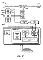
- Fig. 2 illustrates an exemplary embodiment of the disc drive system 128 shown in Fig. 1 as a component of the exemplary disc media marking device 102.
- the disc drive system 128 has a laser assembly 200 that includes a sled 202 which supports a laser 204, an optical pickup unit (OPU) 206, a laser focusing lens 208, a fine actuator 209, and lens supports 210.
- OPU optical pickup unit
- a laser beam 212 is generated by the laser 204 and focused onto a label surface 214 of optical disc media 216.
- the laser beam 212 creates laser marks that correspond to label image data to render an image of the label on the optical disc media 216.
- the disc drive system 128 includes a spindle motor 218, a sled motor 220, and a controller 222.
- controller 222 may be implemented as a printed circuit board employing a combination of various components discussed above with respect to the disc media marking system 100 of Fig. 1.
- controller 222 includes a processor 224 for processing computer/processor-executable instructions from various components stored in a memory 226.
- Processor 224 is typically one or more of the processors 106 discussed above with respect to the disc media marking system 100 of Fig. 1.
- memory 226 is typically the non-volatile memory 112 and/or firmware 116 from the disc media marking system 100 of Fig. 1.
- Drivers 228, including a laser driver, sled driver, and spindle driver are stored in memory 226 and executable on processor 224. Although these components are represented in the Fig. 2 embodiment as software components stored in memory 226 and executable on processor 224, they may also be firmware or hardware components.
- a spindle driver drives the spindle motor 218 to control a rotational speed of disc 216 via spindle 230.
- Spindle driver operates in conjunction with a sled driver which drives the sled motor 220 to control coarse radial positioning of laser assembly 200 with respect to disc 216 along a sled drive mechanism 232.
- the rotational speed of disc 216 and the radial position of laser assembly 200 are controlled such that laser marks are written on the disc 216 as the label surface 214 moves past the laser beam 212 at a constant linear velocity.
- a laser driver controls the firing of laser beam 212 to write laser marks corresponding to a label image onto optical disc media 216.
- Optical pickup unit (OPU) 206 can be implemented as a photodetector that provides laser focus feedback to the laser driver. Additionally, the laser driver controls the intensity of the laser beam 212 to read data maintained on the data side 234 of the optical disc 216 when the disc is positioned such that the data side 234 passes over the laser beam 212.
- a fine actuator driver 236, a radii - DAC count table 238, and a line fitting algorithm 240 are also stored in memory 226.
- Fine actuator driver 236 and line fitting algorithm 240 are executable on processor 224 to generate and manipulate data in radii - DAC count table 238 to determine the gain of (i.e., to calibrate) fine actuator 209.
- fine actuator 209 functions to move focusing lens 208 in a radial direction 242 in small increments in between the larger movements from the sled 202 (i.e., coarse actuator).
- Fine actuator 209 Calibration of fine actuator 209 is achieved through a process involving a DAC 244 (digital to analog converter), a power amplifier 246, a sawtooth reference pattern located on optical disc 216, and various components of the laser assembly 200.
- the calibration process is discussed in greater detail herein below.
- fine actuator driver 236 and line fitting algorithm 240 are represented in the Fig. 2 embodiment as software components stored in memory 226 and executable on processor 224, they may also be firmware or hardware components.
- Computing device interface 248 interfaces the controller 222 of the disc drive system 128 with another electronic or computing device to receive label image data or a label file (not shown).
- the computing device interface 248 can be implemented as an ATAPI (Advanced Technology Attachment Packet Interface), which is one of many small computer parallel or serial device interfaces.
- ATAPI Advanced Technology Attachment Packet Interface
- SCSI small computer system interface
- SCSI defines the structure of commands, the way commands are executed, and the way status is processed.
- Various other physical interfaces include the Parallel Interface, Fiber Channel, IEEE 1394, USB (Universal Serial Bus), and ATA/ATAPI.
- ATAPI is a command execution protocol for use on an ATA interface so that CD-ROM and tape drives can be connected via the same ATA cable with an ATA hard disk drive.
- ATAPI devices generally include CD-ROM drives, CD-recordable drives, CD-rewritable drives, DVD (digital versatile disc) drives, tape drives, super-floppy drives (e.g., ZIP and LS-120), and the like.
- fine actuator driver 236 and line fitting algorithm 240 are configured to generate and manipulate data in radii - DAC count table 238 in order to calibrate fine actuator 209 in a process that involves DAC 244, power amplifier 246, a sawtooth reference pattern located on optical disc 216, and various components of the laser assembly 200.
- the process generally includes moving the laser assembly 200 to a position so that the laser beam 212 is focused at a known radial location on optical disc 216 and then incrementing the radial location while recording current values used for incrementing the radial location.
- the known radial location and incremented radial locations each permit the laser beam 212 to scan a sawtooth reference pattern located on the label surface 214 of disc 216.
- the fine actuator driver 236 increments a DAC count (i.e., a digital number) being input to the DAC.
- the DAC count is recorded into table 238. Incrementing the DAC count adjusts the voltage out of the DAC which drives power amplifier 246. In turn, current supplied to fine actuator 209 by power amplifier 246 is incremented. Changes in the fine actuator 209 current cause the fine actuator 209 to make small adjustments to the focusing lens 208 in the radial direction 242. The small adjustments alter the radius position of laser beam 212 on the sawtooth pattern of disc 216.
- the OPU 206 When the sawtooth pattern is scanned at various radial positions by the laser beam 212, the OPU 206 generates a reflectivity signal corresponding to the sawtooth pattern.
- the duty cycle of the reflectivity signal changes each time the fine actuator 209 adjusts the radial scan location of the laser beam 212 on the sawtooth pattern.
- the fine actuator driver 236 converts the duty cycle of the reflectivity signal into a radius value based on the duty cycle information, the known height of the sawtooth pattern, and the radial position of the sawtooth pattern, and stores the radius value in table 238 along with the corresponding DAC count.
- Line fitting algorithm 240 uses the DAC count and the corresponding radii data from table 238 as coordinate data to calculate a line with a slope that best fits the coordinate data.
- the slope of the best fit line is the gain of the fine actuator 209. That is, the slope of the best fit line calibrates the radial distance that the fine actuator 209 moves the focusing lens 208 for a known current value (i.e., a known current value corresponding to a recorded DAC count) applied to the fine actuator 209.
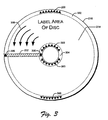
- Fig. 3 illustrates one embodiment of an optical data storage disc 216 having an exemplary reference pattern 300 on a non-data side 214 that enables calibration of fine actuator 209.
- the non-data side 214 i.e., the label side
- the Fig. 3 embodiment shows reference pattern 300 as a sawtooth pattern 300 located in a region on disc 216 at an extreme outer diameter 302 and an extreme inner diameter 304.
- the sawtooth pattern 300 includes two sections of the pattern spaced 180 degrees apart around either the extreme outer diameter 302 or the extreme inner diameter 304 of the disc 216.
- the sawtooth reference pattern 300 is shown in both locations 302 and 304 in Fig.
- the pattern 300 may only be located in one or the other of these locations, and not both.
- the inner and outer diameters, 302 and 304 are preferred locations for a reference pattern 300 in order that the label area of the disc 216 can remain free for labeling.
- this description is not intended to limit the location of reference patterns to the inner and outer diameters 302 and 304 of disc 216, and that such patterns might also be located elsewhere on disc 216.
- Fig. 3 further illustrates part of the sled mechanism 232 shown in Fig. 2 over which a sled 202 carries a laser assembly 200.
- a laser spot 306 is shown at either end of this sled mechanism 232, and in both the extreme outer diameter 302 and extreme inner diameter 304 regions of disc 216.
- Direction arrows 308 indicate the direction of rotation of disc 216.
- laser spot 306 is intended to illustrate how a reference pattern 300 is scanned as the disc 216 rotates the pattern 300 past the laser spot 306, either on the extreme inner diameter 304 or the extreme outer diameter 302 of the disc 216.
- the sawtooth reference pattern 300 (see also Figs. 4-7) can be formed on disc 216 by various processes such as silk screening, etching or embossing.
- the dark patterned areas of reference pattern 300 represent dull areas of low reflectivity on disc 216 (as shown in Figs. 4-7), while the light patterned areas (i.e., the areas that are not marked) represent shiny areas of high reflectivity on disc 216 (also shown in Figs. 4-7).
- scanning areas of varying reflectivity on a disc 216 generates a reflectivity signal through the OPU 206 (Fig. 2) whose amplitude changes in response to the changing reflectivity of the disc 216.
- the sawtooth pattern 300 has a known height and is located at a known radial position on optical disc 216.
- the sawtooth pattern 300 is shown in Fig. 4 beginning at 23.0 millimeters from the inner diameter edge (i.e., the hole) of the optical disc 216.
- the height of the sawtooth pattern 300 shown in Fig. 4 is 1.2 millimeters (i.e., from 23.0 mm to 24.2 mm).
- the location and height of the sawtooth pattern 300 illustrated in Fig. 4 express a preferred implementation of the sawtooth pattern 300, they are not intended as a limitation. Thus, sawtooth pattern 300 might be located closer or farther from the inner edge of optical disc 216 and may be taller or shorter in height.
- pattern 300 is illustrated and discussed throughout as being a sawtooth pattern 300, it is to be understood that other patterns that can provide a linear variation with the disc radius that is measurable and convertible to distance, enabling calibration of the fine actuator are also contemplated.
- Such patterns include, for example, triangular patterns (i.e., half of a sawtooth pattern), stair step patterns, and so on.
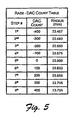
- Figs. 4 and 5 illustrate an exemplary calibration process for a fine actuator 209 involving 9 increments or steps of the fine actuator 209.
- Fig. 4 shows 9 different paths across a sawtooth pattern 300 that a scanning laser beam 212 can take during the calibration process.
- a laser beam 212 is moved to a 1 st location within the sawtooth pattern 300.
- the 1 st location is one that is a number of fine actuator 209 increments away from a "zero current" location.
- the "zero current" location is where there is no current being applied to the fine actuator 209 from power amplifier 246, and thus, where the focusing lens 208 is in a normal resting position.
- a DAC count of zero corresponds to the "zero current" location (i.e., 5 th at 23.6 mm) of the sawtooth pattern 300.
- the calibration process begins by applying a DAC count to DAC 244 that moves the focusing lens 208 (via fine actuator 209) to focus the laser beam 212 at an innermost radial location.
- This 1 st radial location is shown in Fig. 4 as being 23.467 mm from the inner diameter edge of optical disc 216.
- the applied DAC count is known, and it corresponds with a known DAC output voltage that will produce a known current value from power amplifier 246 that will drive the fine actuator 209.
- the known DAC count is recorded into table 238 as shown in Fig. 5.
- a known current value driving the fine actuator 209 might just as readily be recorded and shown in table 238.
- the decimal value of "-400" is illustrated as the DAC count value for the 1 st step of table 238, the number actually applied to the DAC 244 will be a binary number. However, for illustrative purposes, it is easier to show the DAC count numbers in their decimal equivalent values.
- Fig. 4 illustrates two examples of a reflectivity signal 400 that might be generated by OPU 206 from scanning the sawtooth pattern 300 with laser beam 212.
- the duty cycle of the reflectivity signal 400 changes.
- Fig. 4 illustrates two different duty cycles for the reflectivity signal 400 when the sawtooth pattern is scanned at inner (e.g., 23.467 mm) and outer (e.g., 23.725 mm) radial locations. Each time the DAC count is incremented, such as shown in table 238 of Fig. 5, the reflectivity signal 400 has a different duty cycle.
- the fine actuator driver 236 is configured to calculate the corresponding radius and record the radius into table 238, along with the corresponding DAC count (or current value) that generated that radius.
- the radius calculation is based on the known height (e.g., 1.2 mm) of the sawtooth pattern.
- Figs. 4 and 5 illustrate 9 different radii that have been calculated and recorded based on 9 different DAC counts stepped into DAC 244.
- the two sections of the sawtooth pattern 300 spaced 180 degrees apart are used to eliminate errors that might otherwise be generated due to eccentricities in the pattern 300.
- the sawtooth pattern 300 is laid down on the optical disc 216, it is possible that it ends up too far from or too close to the inner diameter edge of the optical disce 216. Therefore, subsequent calculations of radii based on an initial "known" radius of the sawtooth pattern 300 would be in error.
- the sawtooth pattern 300 is laid down on the optical disc 216 as two sections that are 180 degrees apart, any such error can be averaged out.
- the fine actuator driver 236 calculates radii from both of the duty cycles of the resultant reflectivity signals, the radii can be averaged to remove this error.
- the exemplary sawtooth pattern 300 of Fig. 3 and the generation of a reflectivity signal 400 having a varying duty cycle is further illustrated in Figs. 6-8.
- Each of the Figs. 6-8 illustrates the exemplary sawtooth pattern 300, a reflectivity signal 400 response generated by the OPU 206 (Fig. 2) when the laser assembly 200 scans the pattern with a laser beam 212, and the relative pulse durations (i.e., duty cycles) of the reflectivity signals 400.
- the peaks and valleys of the sawtooth pattern 300 define a slanted interface between the low reflectivity region and the high reflectivity region of optical disc 216.
- Fig. 6 illustrates the case where the laser beam 212 is located at the "zero current" radial position, or 5 th position as shown in Figs. 4 and 5.
- the OPU 206 generates a reflectivity signal 400 based on the amount of light reflecting off the disc 216.
- the reflectivity signal 400 has a (nearly) 50% duty cycle. That is, the ratio of the pulse duration 404 to the pulse period 406 is (nearly) 50%.
- the radius calculation is made based on the duty cycle and the known height of the sawtooth pattern 300.
- the pulses 402 in the reflectivity signal 400 of Fig. 6 are rectangular in shape (i.e., saturated at the top and bottom) because the laser beam 212 is very small by comparison to the sawtooth pattern 300, and it is therefore either completely within a low reflectivity region or completely within a high reflectivity region as it scans the pattern 300.
- the laser beam 212 is traveling very fast relative to the sawtooth pattern 300 and therefore traverses the interface between the low and high reflectivity regions virtually instantaneously.
- transitions between high and low signal saturations in the reflectivity signal 400 are also virtually instant, and they appear as straight vertical lines.
- Fig. 7 illustrates the case where the laser beam 212 is located higher on the sawtooth pattern 300 than the "zero current" radial position.
- Fig. 7 may represent, for example, the 9 th position as shown in Fig. 4 and 5.
- the laser beam 212 is at a radial distance that is farther away from the inner diameter of the disc 216.
- the duty cycle of the resultant reflectivity signal 400 is less than it is in the Fig. 6 example.
- the fine actuator driver 236 calculates a corresponding radius based on the duty cycle and the height of the sawtooth pattern 300, and records the radius into table 238 along with the corresponding DAC count (or current value) that generated that radius.
- Fig. 8 illustrates the case where the laser beam 212 is located lower on the sawtooth pattern 300 than the "zero current" radial position.
- Fig. 8 may represent, for example, the 1 st position as shown in Fig. 4 and 5. That is, the laser beam 212 is at a radial distance that is closer to the inner diameter of the optical disc 216. Again, it is evident that the duty cycle of the resultant reflectivity signal 400 is different than those of Figs. 6 and 7.
- the fine actuator driver 236 calculates a corresponding radius based on the different duty cycle and the height of the sawtooth pattern 300, and records the radius into table 238 along with the corresponding DAC count (or current value) that generated that radius..
- the line fitting algorithm 240 uses the data as coordinate data to calculate a line with a slope that best fits the coordinate data.
- the slope of the best fit line calibrates the radial distance that the fine actuator 209 moves the laser beam 212 through focusing lens 208 for a known current value (i.e., a known current value corresponding to a recorded DAC count) applied to the fine actuator 209.
- Fig. 9 illustrates an example of a best fit line calculated by line fitting algorithm 240 based on the values of the DAC count and radii data illustrated in Figs. 4 and 5.
- Line fitting algorithm 240 may be, for example, a least squares line fit that calculates the slope of a line for coordinate data that will minimize the squared error of the line compared to the coordinate data.
- Such line fitting algorithms are well known to those skilled in the art.
- Fig. 9 illustrates a coordinate plot of the data from table 238, with the DAC count data shown along the X axis and the Radius data (in millimeters) shown along the Y axis. Although the radii data may not all fall exactly in a straight line, the line fitting algorithm 240 generates a best fit line with a slope that best calibrates the gain of the fine actuator 209.
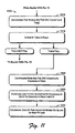
- Example methods for calibrating a fine actuator using a sawtooth pattern in a disc media marking system will now be described with primary reference to the flow diagrams of Figs. 10 - 11.
- the methods apply generally to the exemplary embodiments discussed above with respect to Figs. 1 - 9.
- the elements of the described methods may be performed by any appropriate means including, for example, by hardware logic blocks on an ASIC or by the execution of processor-readable instructions defined on a processor-readable medium.
- a "processor-readable medium,” as used herein, can be any means that can contain, store, communicate, propagate, or transport instructions for use by or execution by a processor.
- a processor-readable medium can be, without limitation, an electronic, magnetic, optical, electromagnetic, infrared, or semiconductor system, apparatus, device, or propagation medium. More specific examples of a processor-readable medium include, among others, an electrical connection (electronic) having one or more wires, a portable computer diskette (magnetic), a random access memory (RAM), a read-only memory (ROM), an erasable programmable-read-only memory (EPROM or Flash memory), an optical fiber (optical), and a portable compact disc read-only memory (CDROM) (optical).
- Fig. 10 shows an exemplary method 1000 for calibrating a fine actuator using a sawtooth pattern in a disc media marking system 100.
- a focusing lens 208 is moved to a known radial location of an optical disc 216.
- the known radial location enables the scanning of a sawtooth pattern 300 located on the label side 214 of the disc 216.
- an updated DAC count number is written to a DAC 244 (digital to analog converter).
- the DAC 244 provides an output voltage in response to the DAC count, and drives a power amplifier 246 as shown at block 1006.
- the power amplifier 246 supplies current which drives a fine actuator 209.
- the fine actuator is configured to move the focusing lens in fine steps in a radial direction 242.
- the current supplied to the fine actuator is associated with, and determined by, the DAC count being input to the DAC by way of the power amplifier 246.
- a sawtooth pattern 300 located on the optical disc 216 is scanned by a laser beam 212.
- the location of the scan across the pattern 300 is controlled in part by the fine actuator which controls movement of the focusing lens 208 in a radial direction 242.
- the sawtooth pattern 300 includes two sections that are located 180 degrees apart from one another on the optical disc 216. Both sections of the pattern 300 are scanned in this circumstance.
- a reflectivity signal is generated from the scanning.
- the reflectivity signal is generated by an OPU 206 (optical pickup unit) according to the reflectivity pattern of the sawtooth pattern 300.
- the reflectivity signal may be two reflectivity signals where the sawtooth pattern includes two sections that are located 180 degrees apart from one another on the optical disc 216.
- a radius is calculated from the duty cycle of the reflectivity signal. Where there are two reflectivity signals, one from each of two sawtooth pattern sections, two radii are calculated and then averaged in order to generate the calculated radius for block 1014.
- the method 1000 continues on Fig. 11, at block 1016.
- the radius and the DAC count are recorded into a table. The radius and DAC count are associated within the table as corresponding to one another.
- the table is checked to see if it is full. Whether or not the table is full depends in part on how many DAC count increments will be made in the calibration process. The number of increments is preferably 9, but this is not intended as a limitation. Thus, in the described embodiment, the table is full if 9 DAC counts and 9 radii have been recorded into the table. If the table is not full, the method (i.e., calibration process) returns to block 1004 of Fig. 10, and the previously described steps are performed again. If the table is full, the method continues at block 1020.
- the radii and DAC count numbers recorded in the table are configured as coordinate data.
- the coordinate data is manipulated by a line fitting algorithm in order to generate a best line fit for the coordinates.
- the gain of the fine actuator is then calibrated based on the slope of the best fit line, as shown at block 1024.
Landscapes
- Optical Recording Or Reproduction (AREA)
- Optical Record Carriers And Manufacture Thereof (AREA)
- Moving Of The Head For Recording And Reproducing By Optical Means (AREA)
- Manufacturing Optical Record Carriers (AREA)
Claims (12)
- Ein prozessorlesbares Medium (108, 112, 114, 226), das prozessorausführbare Befehle umfasst, die konfiguriert sind zum:Abtasten (1010) eines Referenzmusters (300) auf einer Platte (216) unter Verwendung einer optischen Aufnahmeeinheit (206), die konfiguriert ist, um durch eine Grobbetätigungsvorrichtung (220) und eine Feinbetätigungsvorrichtung (209) radial relativ zu der Platte (216) bewegt zu werden, wobei die Feinbetätigungsvorrichtung (209) veranlasst wird, die optische Aufnahmeeinheit (206) relativ zu der Platte (216) zu einer radialen Position zu bewegen, abhängig von dem Wert eines Betätigungsvorrichtungssteuersignals, wobei das Referenzmuster (300) eine lineare Variation mit radialer Position auf der Platte definiert, wobei die optische Aufnahmeeinheit (206) während dem Abtasten (1010) nur durch die Feinbetätigungsvorrichtung (209) bewegt wird, um ein jeweiliges Mustersignal an einer Mehrzahl von radialen Positionen derselben zu erzeugen, und dadurch eine Tabelle (238) von koordinierten Betätigungsvorrichtungssteuersignalen und radialen Positionsdaten zu erzeugen; undKalibrieren (1022, 1024) der Feinbetätigungsvorrichtung (209) basierend auf der Tabelle (238) von koordinierten Daten.
- Ein prozessorlesbares Medium (108, 112, 114, 226) gemäß Anspruch 1, bei dem das Abtasten (1010) folgende Schritte umfasst:Erzeugen (1012) eines Reflexionssignals (400) auf der Basis des Referenzmusters (300);Umwandeln (1014) eines Tastverhältnisses des Reflexionssignals (400) in einen Radiuswert; undAufzeichnen (1016) des Radiuswerts und eines zugeordneten Digital/Analog-Wandler-Zählwerts in der Tabelle (238) .
- Ein prozessorlesbares Medium (108, 112, 114, 226) gemäß Anspruch 1 oder Anspruch 2, bei dem das Kalibrieren (1022, 1024) folgende Schritte umfasst:Durchführen (1022) eines Linien-Fit-Algorithmus (240) auf den koordinierten Daten, um eine Bester-Fit-Linie zu erzeugen; undKalibrieren (1024) der Feinbetätigungsvorrichtung (209) basierend auf der Steigung der Bester-Fit-Linie.
- Ein prozessorlesbares Medium (108, 112, 114, 226) gemäß einem der vorhergehenden Ansprüche, bei dem das Abtasten (1010) folgende Schritte umfasst:Schreiben (1004) einer Zahl in einen Digital/Analog-Wandler (244);Treiben (1006) eines Leistungsverstärkers (246) mit einer DAW-Ausgangsspannung;Treiben (1008) eines Betätigungsvorrichtungsstroms mit dem Leistungsverstärker (246);Ändern (1004) der Zahl, die in den DAW (244) geschrieben ist, n mal um einen bekannten Betrag;für jede Zahl, die in den DAW (244) geschrieben ist, Berechnen (1014) eines Radius von einem Tastverhältnis eines Reflexionssignals (400), das von dem Referenzmuster (300) erzeugt wird; undAufzeichnen (1016) jedes Radius und jeder Zahl, die in den DAW (244) geschrieben sind, in der Tabelle.
- Ein prozessorlesbares Medium (108, 112, 114, 226) gemäß einem der vorhergehenden Ansprüche, wobei das Abtasten (1010) folgende Schritte umfasst:Abtasten (1010) einer ersten Hälfe des Referenzmusters (300) ;Berechnen (1014) eines ersten Radius basierend auf der ersten Hälfte des Referenzmusters (300);Abtasten (1010) einer zweiten Hälfte des Referenzmusters (300);Berechnen (1014) eines zweiten Radius basierend auf der zweiten Hälfte des Referenzmusters (300); undMitteln (1014) des ersten Radius und des zweiten Radius, um die koordinierten Daten zu erzeugen.
- Ein prozessorlesbares Medium (108, 112, 114, 226) gemäß Anspruch 5, bei dem die erste Hälfte des Referenzmusters (300) und die zweite Hälfte des Referenzmusters (300) auf der Nicht-Daten-Seite (214) der Platte (216) 180 Grad voneinander entfernt sind.
- Ein prozessorlesbares Medium (108, 112, 114, 226) gemäß einem der vorhergehenden Ansprüche, bei dem das Referenzmuster (300) ein Sägezahnreferenzmuster ist.
- Eine Optische-Platte-Lese/Schreib-Vorrichtung (102), die das prozessorlesbare Medium (108, 112, 114, 226) gemäß einem der vorhergehenden Ansprüche umfasst.
- Ein Plattenantriebssystem (128), das folgende Merkmale umfasst:einen Scanner (206, 208, 212), der konfiguriert ist, um ein Referenzmuster (300) auf einer optischen Platte (216) zu lesen, die eine lineare Variation mit radialer Position auf der Platte (216) umfasst, wobei der Scanner eine optische Aufnahmeeinheit (206) umfasst, die konfiguriert ist, um durch eine Grobbetätigungsvorrichtung (220) und eine Feinbetätigungsvorrichtung (209) radial relativ zu der Platte (216) bewegt zu werden, die konfiguriert ist, um kleine radiale Bewegungen (242) des Scanners (206, 208, 212) zu steuern, wobei die Feinbetätigungsvorrichtung (209) veranlasst wird, die optische Aufnahmeeinheit (206) relativ zu der Platte (216) zu einer radialen Position zu bewegen, abhängig von dem Wert eines Betätigungsvorrichtungssteuersignals, wobei die optische Aufnahmeeinheit (206) während einer Kalibrierungsabtastung (1010) nur durch die Feinbetätigungsvorrichtung (209) bewegt wird, um das Referenzmuster (300) zu erfassen, und dadurch ein jeweiliges Mustersignal an einer Mehrzahl von radialen Positionen derselben zu erzeugen, und um eine Tabelle (238) von koordinierten Betätigungsvorrichtungssteuersignalen und radialen Positionsdaten zu erzeugen; undeine Einrichtung zum Kalibrieren der Feinbetätigungsvorrichtung (209) basierend auf der Tabelle (238) von koordinierten Daten.
- Ein Plattenantriebssystem (128) gemäß Anspruch 9, das ferner folgende Merkmale umfasst:einen Prozessor (224), der konfiguriert ist, um eine binäre Zahl in einen Digital/Analog-Wandler (244) zu schreiben, und die binäre Zahl in gleichen Schritten zu inkrementieren;den Digital/Analog-Wandler (244), der konfiguriert ist, um eine Ausgangsspannung für jede binäre Zahl zu erzeugen; undeinen Leistungsverstärker (246), der konfiguriert ist, um die Feinbetätigungsvorrichtung (209) basierend auf jeder Ausgangsspannung mit aktuellen Werten zu treiben.
- Ein Plattenantriebssystem (128) gemäß Anspruch 10, das ferner folgende Merkmale umfasst:eine Tabelle (238) von koordinierten Daten, die die binären Zahlen und einen Radiuswert umfasst, der von dem Referenzmuster (300) für jede binäre Zahl berechnet wird; undeinen Linien-Fit-Algorithmus (240), der konfiguriert ist, um von den koordinierten Daten eine Bester-Fit-Linie zu erzeugen und die Steigung der Bester-Fit-Linie zu bestimmen.
- Eine Optische-Platte-Lese/Schreib-Vorrichtung (102), die das Plattenantriebssystem (128) gemäß einem der Ansprüche 9 bis 11 umfasst.
Applications Claiming Priority (2)
| Application Number | Priority Date | Filing Date | Title |
|---|---|---|---|
| US661333 | 2003-09-12 | ||
| US10/661,333 US7219840B2 (en) | 2003-01-17 | 2003-09-12 | Calibrating fine actuator using a reference pattern |
Publications (2)
| Publication Number | Publication Date |
|---|---|
| EP1515318A1 EP1515318A1 (de) | 2005-03-16 |
| EP1515318B1 true EP1515318B1 (de) | 2006-05-24 |
Family
ID=34136790
Family Applications (1)
| Application Number | Title | Priority Date | Filing Date |
|---|---|---|---|
| EP04254304A Expired - Lifetime EP1515318B1 (de) | 2003-09-12 | 2004-07-16 | Kalibrierung eines Feinpositionierers mittels eines Referenzmusters auf einer spurlosen Oberfläche einer optischen Platte |
Country Status (9)
| Country | Link |
|---|---|
| US (1) | US7219840B2 (de) |
| EP (1) | EP1515318B1 (de) |
| JP (1) | JP4150708B2 (de) |
| KR (1) | KR100488329B1 (de) |
| CN (1) | CN100555426C (de) |
| DE (1) | DE602004000966T2 (de) |
| MY (1) | MY142495A (de) |
| SG (1) | SG110112A1 (de) |
| TW (1) | TWI277958B (de) |
Families Citing this family (22)
| Publication number | Priority date | Publication date | Assignee | Title |
|---|---|---|---|---|
| JP4066927B2 (ja) * | 2003-09-30 | 2008-03-26 | ヤマハ株式会社 | 可視画像形成方法、プログラムおよび可視画像形成システム |
| US7233557B2 (en) | 2004-05-28 | 2007-06-19 | Hewlett-Packard Development Company, L.P. | Method for identifying location on an optical disk |
| US7496026B2 (en) * | 2004-12-11 | 2009-02-24 | Hewlett-Packard Development Company, L.P. | Optical disc and method of printing optical disc |
| US7349297B2 (en) | 2004-12-11 | 2008-03-25 | Hanks Darwin M | Method and apparatus for acquiring an index mark |
| KR20070095967A (ko) * | 2004-12-23 | 2007-10-01 | 코닌클리케 필립스 일렉트로닉스 엔.브이. | 시각 라벨의 기록 시스템 |
| EP1720165B1 (de) * | 2005-03-23 | 2010-10-06 | Hitachi-LG Data Storage Korea, Inc. | Verfahren für den Ausgleich eines Positionsfehlers bei einer optischen Plattenvorrichtung |
| KR100662935B1 (ko) | 2005-04-26 | 2006-12-28 | 주식회사 히타치엘지 데이터 스토리지 코리아 | 광디스크장치의 포지션오차 보상방법 |
| US7646685B2 (en) * | 2005-06-11 | 2010-01-12 | Hewlett-Packard Development Company, L.P. | Tracing discrete spiral path relative to optical disc |
| JP3995008B2 (ja) | 2005-06-30 | 2007-10-24 | ヤマハ株式会社 | 光ディスク記録装置 |
| KR100704078B1 (ko) * | 2005-07-08 | 2007-04-06 | 엘지전자 주식회사 | 디스크 매체의 라벨면에 인쇄하는 방법 및 장치 |
| KR100703378B1 (ko) * | 2005-07-08 | 2007-04-03 | 엘지전자 주식회사 | 디스크 매체의 라벨면에 인쇄하는 방법 및 장치 |
| US7265936B1 (en) * | 2006-03-15 | 2007-09-04 | Samsung Electronics Co., Ltd. | Algorithm for DSA/microactuator total loop gain calibration |
| JP4549315B2 (ja) * | 2006-06-05 | 2010-09-22 | 三洋電機株式会社 | 光ディスク装置 |
| US8094176B2 (en) * | 2006-09-22 | 2012-01-10 | Pioneer Corporation | Drawing apparatus and method, and computer program |
| JP2008097740A (ja) | 2006-10-13 | 2008-04-24 | Sanyo Electric Co Ltd | 光ディスク装置 |
| US20100026778A1 (en) * | 2006-12-15 | 2010-02-04 | Pioneer Corporation | Drawing device and method, and computer program |
| US8547817B2 (en) * | 2007-09-28 | 2013-10-01 | Hewlett-Packard Development Company, L.P. | Methods and apparatus for merging pre-rendered and dynamic optical-storage label indicia |
| US7813075B2 (en) | 2007-10-22 | 2010-10-12 | Hitachi Global Storage Technologies Netherlands B.V. | System, method and apparatus for performing metrology on patterned media disks with test pattern areas |
| US8917302B2 (en) * | 2008-02-25 | 2014-12-23 | International Business Machines Corporation | Apparatus and method to display information using an information layer laminate |
| JP4955593B2 (ja) * | 2008-03-17 | 2012-06-20 | ルネサスエレクトロニクス株式会社 | 駆動信号生成装置及び描画装置 |
| JP4955592B2 (ja) * | 2008-03-17 | 2012-06-20 | ルネサスエレクトロニクス株式会社 | 描画装置及び駆動信号生成装置 |
| JP7127512B2 (ja) * | 2018-11-28 | 2022-08-30 | 株式会社Jvcケンウッド | 光ディスク装置及び光ディスク回転位置検出方法 |
Family Cites Families (54)
| Publication number | Priority date | Publication date | Assignee | Title |
|---|---|---|---|---|
| US3426337A (en) * | 1964-12-21 | 1969-02-04 | Ibm | Positioning system for random access device |
| US4027217A (en) * | 1975-02-12 | 1977-05-31 | Pertec Computer Corporation | Speed control for a motor |
| JPS60124020A (ja) * | 1983-12-08 | 1985-07-02 | Fujitsu Ltd | デ−タ記憶装置のヘッド位置検出方式 |
| JPS6132113A (ja) * | 1984-07-23 | 1986-02-14 | Seiko Instr & Electronics Ltd | ロボツト制御方式 |
| US4783705A (en) * | 1986-02-27 | 1988-11-08 | Quantum Corporation | High capacity disk file with embedded sector servo and SCSI interface |
| US5005089A (en) * | 1988-05-10 | 1991-04-02 | Quantum Corp. | High performance, high capacity micro-winchester disk drive |
| US4967286A (en) * | 1988-12-12 | 1990-10-30 | Disctronics Manufacturing, Inc. | Method and apparatus for forming a digital image on an optical recording disc |
| US5121260A (en) * | 1989-06-22 | 1992-06-09 | Digital Equipment Corporation | Read channel optimization system |
| US5182741A (en) * | 1989-08-25 | 1993-01-26 | Sharp Kabushiki Kaisha | Optical disk recording/reproducing device utilizing a constant angular velocity method with a constant linear velocity formatted optical disk |
| US5021937A (en) * | 1989-10-18 | 1991-06-04 | Lambda Electronics Inc. | Maximum duty cycle limiting of pulse width modulators |
| JP3109866B2 (ja) * | 1990-11-17 | 2000-11-20 | 太陽誘電株式会社 | 光学式情報記録担体用基板及びその製造方法 |
| US5688173B1 (en) * | 1993-03-31 | 1999-10-05 | Sega Enterprises Kk | Information storage medium and electronic device using the same |
| DE4311683C2 (de) * | 1993-04-08 | 1996-05-02 | Sonopress Prod | Plattenförmiger optischer Speicher und Verfahren zu dessen Herstellung |
| US6102800A (en) * | 1993-07-28 | 2000-08-15 | Sega Enterprises, Ltd. | Information storage medium and electronic device using the same |
| CN1064165C (zh) * | 1993-07-28 | 2001-04-04 | 世嘉企业股份有限公司 | 信息记录媒体以及利用它的电子装置 |
| EP0643391B1 (de) * | 1993-09-07 | 2000-02-02 | Hitachi, Ltd. | Informationsaufzeichnungsträger, optische Platten und Wiedergabesystem |
| US5627895A (en) * | 1993-11-29 | 1997-05-06 | Sega Enterprises, Ltd. | Electronic device for detecting selected visually perceptible indication information on an information storage medium for security comparison |
| TW264553B (de) * | 1994-04-26 | 1995-12-01 | Hitachi Building System Service Kk | |
| WO1995034066A1 (en) | 1994-06-06 | 1995-12-14 | Maxtor Corporation | Factory calibration of servo parameters in a hard disk drive |
| JPH0845298A (ja) * | 1994-07-29 | 1996-02-16 | Nec Corp | 差動サンプル・ホールド回路 |
| JPH08180463A (ja) * | 1994-12-20 | 1996-07-12 | Pioneer Video Corp | 光学式ディスク |
| JPH08194972A (ja) * | 1995-01-12 | 1996-07-30 | Pioneer Video Corp | 光ディスク及びその製造装置 |
| JP3300186B2 (ja) * | 1995-02-28 | 2002-07-08 | パイオニア株式会社 | 光ディスクプレーヤ |
| US5729533A (en) | 1995-09-12 | 1998-03-17 | Wae Manufacturing Inc. | Two-sided, light-readable information recording disc stacks and methods of making same |
| GB9605729D0 (en) * | 1996-03-19 | 1996-05-22 | Applied Holographics | Optical data storage disc |
| US5764430A (en) * | 1996-04-01 | 1998-06-09 | International Business Machines Corporation | Disk drive having optimized spindle speed for environment |
| US5958651A (en) * | 1996-07-11 | 1999-09-28 | Wea Manufacturing Inc. | Methods for providing artwork on plastic information discs |
| US6195322B1 (en) * | 1996-07-25 | 2001-02-27 | Sony Corporation | Disk drive device and method of setting rotational speed thereof |
| US5790250A (en) * | 1996-11-04 | 1998-08-04 | Ail Systems, Inc. | Apparatus and method for real-time spectral alignment for open-path fourier transform infrared spectrometers |
| JP2845230B2 (ja) * | 1996-12-16 | 1999-01-13 | 日本電気株式会社 | 光ディスク装置のビームスポット速度検出器 |
| US6019151A (en) * | 1997-01-07 | 2000-02-01 | Eastman Kodak Company | Printing onto discs such as compact discs and the like |
| US5781221A (en) * | 1997-02-28 | 1998-07-14 | Eastman Kodak Company | Method of printing visually readable information on a compact disk |
| US5915858A (en) * | 1997-03-07 | 1999-06-29 | Eastman Kodak Company | Organizing pixels of different density levels for printing human readable information on CDs |
| US5766495A (en) * | 1997-03-13 | 1998-06-16 | Wea Manufacturing Inc. | Methods for providing generic and specific artwork on plastic information discs |
| EP0867881A3 (de) * | 1997-03-26 | 2002-10-23 | Sony Corporation | Auzeichnungsgerät für Aufzeichnungsmedium, Methode und Aufzeichnungsmedium |
| JP3511450B2 (ja) * | 1997-09-12 | 2004-03-29 | 株式会社ミツトヨ | 光学式測定装置の位置校正方法 |
| US5949752A (en) * | 1997-10-30 | 1999-09-07 | Wea Manufacturing Inc. | Recording media and methods for display of graphic data, text, and images |
| KR100282939B1 (ko) * | 1997-11-25 | 2001-03-02 | 윤종용 | 광디스크드라이브에서의 스핀들모터 회전속도 제어방법 |
| US6270176B1 (en) * | 1997-12-11 | 2001-08-07 | Compulog Corporation | Method and apparatus for printing labels on digital recording media |
| US6074031A (en) * | 1997-12-11 | 2000-06-13 | Compulog Corporation | Method and apparatus for printing labels on digital recording media |
| US6440248B1 (en) * | 1998-02-02 | 2002-08-27 | Wea Manufacturing Inc. | Two-sided graphical image DVDs and methods for making same |
| US5997976A (en) * | 1998-02-12 | 1999-12-07 | Wea Manufacturing Inc. | Etched mold surface for use in making light-readable discs |
| WO1999044196A1 (en) * | 1998-02-27 | 1999-09-02 | Doug Carson & Associates, Inc. | Individual adjustment of pit and land transition locations in an optical disc mastering process |
| US5967676A (en) * | 1998-03-31 | 1999-10-19 | Microtech Conversion Systems, Inc. | Image orientation system for disk printing |
| US6264295B1 (en) | 1998-04-17 | 2001-07-24 | Elesys, Inc. | Radial printing system and methods |
| US6386667B1 (en) * | 1998-04-24 | 2002-05-14 | Hewlett-Packard Company | Technique for media coverage using ink jet writing technology |
| US6384929B1 (en) * | 1998-06-17 | 2002-05-07 | Wordtech, Inc. | Self-orienting printer controller for printing on the non-recordable label face of a compact disk |
| US6124011A (en) | 1998-09-03 | 2000-09-26 | Wea Manufacturing, Inc. | Information-bearing discs and methods of fabrication |
| US6202550B1 (en) * | 1998-12-30 | 2001-03-20 | Eastman Kodak Company | Printer and method for printing indicia on a compact disk using a plurality of ink jet or laser rotatable print heads |
| US6403191B1 (en) * | 1999-09-21 | 2002-06-11 | Strata-Tac, Inc. | Laminate with integrated compact disk label and methods |
| US6452883B2 (en) * | 2000-02-24 | 2002-09-17 | Via Technologies, Inc. | Method and apparatus applied in an optical storage device for estimating radial speed of disc |
| US7268794B2 (en) * | 2000-10-30 | 2007-09-11 | Yamaha Corporation | Method of printing label on optical disk, optical disk unit, and optical disk |
| US7109483B2 (en) * | 2000-11-17 | 2006-09-19 | Ebara Corporation | Method for inspecting substrate, substrate inspecting system and electron beam apparatus |
| US7671880B2 (en) | 2003-01-17 | 2010-03-02 | Hewlett-Packard Development Company, L.P. | Optical disk labeling system and method |
-
2003
- 2003-09-12 US US10/661,333 patent/US7219840B2/en not_active Expired - Fee Related
-
2004
- 2004-03-19 TW TW093107463A patent/TWI277958B/zh not_active IP Right Cessation
- 2004-03-22 MY MYPI20041006A patent/MY142495A/en unknown
- 2004-07-12 CN CNB2004100699332A patent/CN100555426C/zh not_active Expired - Fee Related
- 2004-07-16 EP EP04254304A patent/EP1515318B1/de not_active Expired - Lifetime
- 2004-07-16 DE DE602004000966T patent/DE602004000966T2/de not_active Expired - Lifetime
- 2004-07-30 SG SG200404358A patent/SG110112A1/en unknown
- 2004-09-10 KR KR10-2004-0072382A patent/KR100488329B1/ko not_active Expired - Fee Related
- 2004-09-13 JP JP2004265490A patent/JP4150708B2/ja not_active Expired - Fee Related
Also Published As
| Publication number | Publication date |
|---|---|
| CN100555426C (zh) | 2009-10-28 |
| US20040141046A1 (en) | 2004-07-22 |
| SG110112A1 (en) | 2005-04-28 |
| DE602004000966T2 (de) | 2007-05-03 |
| TW200511237A (en) | 2005-03-16 |
| TWI277958B (en) | 2007-04-01 |
| JP2005093052A (ja) | 2005-04-07 |
| EP1515318A1 (de) | 2005-03-16 |
| KR100488329B1 (ko) | 2005-05-11 |
| HK1073012A1 (en) | 2005-09-16 |
| DE602004000966D1 (de) | 2006-06-29 |
| JP4150708B2 (ja) | 2008-09-17 |
| MY142495A (en) | 2010-11-30 |
| KR20050027048A (ko) | 2005-03-17 |
| CN1595510A (zh) | 2005-03-16 |
| US7219840B2 (en) | 2007-05-22 |
Similar Documents
| Publication | Publication Date | Title |
|---|---|---|
| EP1515318B1 (de) | Kalibrierung eines Feinpositionierers mittels eines Referenzmusters auf einer spurlosen Oberfläche einer optischen Platte | |
| US7084894B2 (en) | Optical disc drive focusing apparatus | |
| EP1450366B1 (de) | Markierung eines Plattenmediums | |
| US20130100790A1 (en) | Optical beam positioning at radial location of optical disc using series of segments at edge of optical disc | |
| US7196715B2 (en) | Speed control using drive current profile | |
| US7496026B2 (en) | Optical disc and method of printing optical disc | |
| US7596067B2 (en) | Method of laser spot location and adjustment thereof | |
| HK1073012B (en) | Calibrating a fine actuator using a reference pattern on a trackless optical disc surface | |
| US7188348B2 (en) | Optical disc drive apparatus and method | |
| US7324419B2 (en) | Focus control via AC input signal | |
| US7443772B2 (en) | Focus offset calibration | |
| HK1083148B (en) | Optical disc drive focusing apparatus for printing an image on a label region | |
| HK1116592A (en) | Focus control via ac input signal | |
| HK1065634A (en) | Disc media marking |
Legal Events
| Date | Code | Title | Description |
|---|---|---|---|
| PUAI | Public reference made under article 153(3) epc to a published international application that has entered the european phase |
Free format text: ORIGINAL CODE: 0009012 |
|
| 17P | Request for examination filed |
Effective date: 20040812 |
|
| AK | Designated contracting states |
Kind code of ref document: A1 Designated state(s): AT BE BG CH CY CZ DE DK EE ES FI FR GB GR HU IE IT LI LU MC NL PL PT RO SE SI SK TR |
|
| AX | Request for extension of the european patent |
Extension state: AL HR LT LV MK |
|
| 17Q | First examination report despatched |
Effective date: 20050525 |
|
| REG | Reference to a national code |
Ref country code: HK Ref legal event code: DE Ref document number: 1073012 Country of ref document: HK |
|
| GRAP | Despatch of communication of intention to grant a patent |
Free format text: ORIGINAL CODE: EPIDOSNIGR1 |
|
| AKX | Designation fees paid |
Designated state(s): DE ES FR GB IT NL |
|
| GRAS | Grant fee paid |
Free format text: ORIGINAL CODE: EPIDOSNIGR3 |
|
| GRAA | (expected) grant |
Free format text: ORIGINAL CODE: 0009210 |
|
| AK | Designated contracting states |
Kind code of ref document: B1 Designated state(s): DE ES FR GB IT NL |
|
| PG25 | Lapsed in a contracting state [announced via postgrant information from national office to epo] |
Ref country code: NL Free format text: LAPSE BECAUSE OF FAILURE TO SUBMIT A TRANSLATION OF THE DESCRIPTION OR TO PAY THE FEE WITHIN THE PRESCRIBED TIME-LIMIT Effective date: 20060524 Ref country code: IT Free format text: LAPSE BECAUSE OF FAILURE TO SUBMIT A TRANSLATION OF THE DESCRIPTION OR TO PAY THE FEE WITHIN THE PRESCRIBED TIME-LIMIT;WARNING: LAPSES OF ITALIAN PATENTS WITH EFFECTIVE DATE BEFORE 2007 MAY HAVE OCCURRED AT ANY TIME BEFORE 2007. THE CORRECT EFFECTIVE DATE MAY BE DIFFERENT FROM THE ONE RECORDED. Effective date: 20060524 |
|
| REG | Reference to a national code |
Ref country code: GB Ref legal event code: FG4D |
|
| REF | Corresponds to: |
Ref document number: 602004000966 Country of ref document: DE Date of ref document: 20060629 Kind code of ref document: P |
|
| PGFP | Annual fee paid to national office [announced via postgrant information from national office to epo] |
Ref country code: FR Payment date: 20060717 Year of fee payment: 3 |
|
| PG25 | Lapsed in a contracting state [announced via postgrant information from national office to epo] |
Ref country code: ES Free format text: LAPSE BECAUSE OF FAILURE TO SUBMIT A TRANSLATION OF THE DESCRIPTION OR TO PAY THE FEE WITHIN THE PRESCRIBED TIME-LIMIT Effective date: 20060904 |
|
| REG | Reference to a national code |
Ref country code: HK Ref legal event code: GR Ref document number: 1073012 Country of ref document: HK |
|
| NLV1 | Nl: lapsed or annulled due to failure to fulfill the requirements of art. 29p and 29m of the patents act | ||
| PLBE | No opposition filed within time limit |
Free format text: ORIGINAL CODE: 0009261 |
|
| STAA | Information on the status of an ep patent application or granted ep patent |
Free format text: STATUS: NO OPPOSITION FILED WITHIN TIME LIMIT |
|
| 26N | No opposition filed |
Effective date: 20070227 |
|
| EN | Fr: translation not filed | ||
| PG25 | Lapsed in a contracting state [announced via postgrant information from national office to epo] |
Ref country code: FR Free format text: LAPSE BECAUSE OF FAILURE TO SUBMIT A TRANSLATION OF THE DESCRIPTION OR TO PAY THE FEE WITHIN THE PRESCRIBED TIME-LIMIT Effective date: 20070309 |
|
| PGFP | Annual fee paid to national office [announced via postgrant information from national office to epo] |
Ref country code: GB Payment date: 20140624 Year of fee payment: 11 |
|
| PGFP | Annual fee paid to national office [announced via postgrant information from national office to epo] |
Ref country code: DE Payment date: 20140620 Year of fee payment: 11 |
|
| REG | Reference to a national code |
Ref country code: DE Ref legal event code: R119 Ref document number: 602004000966 Country of ref document: DE |
|
| GBPC | Gb: european patent ceased through non-payment of renewal fee |
Effective date: 20150716 |
|
| PG25 | Lapsed in a contracting state [announced via postgrant information from national office to epo] |
Ref country code: DE Free format text: LAPSE BECAUSE OF NON-PAYMENT OF DUE FEES Effective date: 20160202 Ref country code: GB Free format text: LAPSE BECAUSE OF NON-PAYMENT OF DUE FEES Effective date: 20150716 |