EP1515180B1 - Variables optisches filter - Google Patents
Variables optisches filter Download PDFInfo
- Publication number
- EP1515180B1 EP1515180B1 EP03736103.7A EP03736103A EP1515180B1 EP 1515180 B1 EP1515180 B1 EP 1515180B1 EP 03736103 A EP03736103 A EP 03736103A EP 1515180 B1 EP1515180 B1 EP 1515180B1
- Authority
- EP
- European Patent Office
- Prior art keywords
- phase difference
- variable
- wavelength
- optical filter
- polarizer
- Prior art date
- Legal status (The legal status is an assumption and is not a legal conclusion. Google has not performed a legal analysis and makes no representation as to the accuracy of the status listed.)
- Expired - Lifetime
Links
Images




Classifications
-
- G—PHYSICS
- G02—OPTICS
- G02F—OPTICAL DEVICES OR ARRANGEMENTS FOR THE CONTROL OF LIGHT BY MODIFICATION OF THE OPTICAL PROPERTIES OF THE MEDIA OF THE ELEMENTS INVOLVED THEREIN; NON-LINEAR OPTICS; FREQUENCY-CHANGING OF LIGHT; OPTICAL LOGIC ELEMENTS; OPTICAL ANALOGUE/DIGITAL CONVERTERS
- G02F1/00—Devices or arrangements for the control of the intensity, colour, phase, polarisation or direction of light arriving from an independent light source, e.g. switching, gating or modulating; Non-linear optics
- G02F1/01—Devices or arrangements for the control of the intensity, colour, phase, polarisation or direction of light arriving from an independent light source, e.g. switching, gating or modulating; Non-linear optics for the control of the intensity, phase, polarisation or colour
- G02F1/09—Devices or arrangements for the control of the intensity, colour, phase, polarisation or direction of light arriving from an independent light source, e.g. switching, gating or modulating; Non-linear optics for the control of the intensity, phase, polarisation or colour based on magneto-optical elements, e.g. exhibiting Faraday effect
-
- G—PHYSICS
- G02—OPTICS
- G02F—OPTICAL DEVICES OR ARRANGEMENTS FOR THE CONTROL OF LIGHT BY MODIFICATION OF THE OPTICAL PROPERTIES OF THE MEDIA OF THE ELEMENTS INVOLVED THEREIN; NON-LINEAR OPTICS; FREQUENCY-CHANGING OF LIGHT; OPTICAL LOGIC ELEMENTS; OPTICAL ANALOGUE/DIGITAL CONVERTERS
- G02F2203/00—Function characteristic
- G02F2203/05—Function characteristic wavelength dependent
- G02F2203/055—Function characteristic wavelength dependent wavelength filtering
Definitions
- the present invention relates generally to a variable optical filter used, for example, in an optical communication system, and more particularly, to a variable optical filter that has two phase difference elements disposed at the front and back, respectively, of a variable Faraday rotator in an optical path and sets the optic axes of the two phase difference elements in different azimuths to ensure improved linearity (linearity when transmittance is expressed in logarithmic form) over a wide operational slope range.
- one or a plurality of optical amplifiers such as erbium-doped fiber amplifiers (EDFA) are incorporated in each repeater to amplify an attenuated signal for transmission over a long distance.
- the amplification vs. wavelength characteristic of the EDFA affects the communication quality.
- the EDFAs develop a slope in the wavelength characteristic due to their secular change and variations in the input signal light. If this slope accumulates in a plurality of the concatenated EDFAs, the optical signal-to-noise deteriorates in channels with a large loss.
- variable optical filter is used to correct this slope.
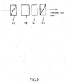
- the background art includes a variable optical filter having a first polarizer, a phase difference element, a variable Faraday rotator and a second polarizer arranged in this order along the optical axis. See Japanese Patent Application Laid-open Publication No. 11-212044 .
- the transmittance has dependency on the rotation angle of the variable Faraday rotator and the wavelength, and the wavelength characteristic of the phase difference elements changes like a trigonometric function.
- the slope of the EDFAs is known to vary linearly when the wavelength characteristic thereof is expressed in logarithmic form. Despite the demand to correct this slope with the utmost accuracy, the background art has failed to sufficiently meet this demand.
- variable optical filter generally in accordance with the preamble of claim 1 is known from JP-6-130339 .
- variable optical filter capable of improving the linearity in the loss vs. wavelength characteristic expressed in logarithmic form over a given wide range of operating bandwidths. It is another object of the present invention to provide a variable optical filter capable of reducing variations in the mean insertion loss over a given wide range of operating bandwidths.
- the present invention provides a variable optical filter comprising: a first polarizer; a first phase difference element operable to generate a phase difference; a variable Faraday rotator operable to impart a variable Faraday rotation; a second phase difference element operable to generate a phase difference; and a second polarizer, wherein said polarizers, said variable Faraday rotator, and said phase difference elements are arranged in the aforementioned order along the optical axis, wherein when the rotation direction of a rotation angle ⁇ of said Faraday rotator is positive, an angle ⁇ formed by the transmitted polarization azimuths of the first and second polarizers is set to ⁇ >0, the angle ⁇ 1 formed by the optic axis of the first phase difference element and the transmitted polarization azimuth of the first polarizer is set to ⁇ 1 ⁇ 0, and the angle ⁇ 2 formed by the optic axis of the second phase difference element and the transmitted polarization azimuth of the first polarizer is set to ⁇
- Fig. 1 shows a basic configuration of a variable optical filter according to the present invention.
- This variable optical filter has a first polarizer 10, a first phase difference element 12 operable to generate a phase difference, a variable Faraday rotator 14 operable to impart a variable Faraday rotation, a second phase difference element 16 operable to generate a phase difference and a second polarizer 18 arranged in this order along the optical axis.
- a first polarizer 10 a first phase difference element 12 operable to generate a phase difference
- a variable Faraday rotator 14 operable to impart a variable Faraday rotation
- a second phase difference element 16 operable to generate a phase difference
- a second polarizer 18 arranged in this order along the optical axis.
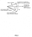
- ⁇ 1 and ⁇ 2 when the angles formed by the optic axes of the first and second phase difference elements and the transmitted polarization azimuth of the first polarizer are assumed respectively to be ⁇ 1 and ⁇ 2 , these ⁇ 1 and
- an angle ⁇ formed by the transmitted polarization azimuths of the first and second polarizers is set ⁇ >0
- the angle ⁇ 1 formed by the optic axis of the first phase difference element and the transmitted polarization azimuth of the first polarizer is set ⁇ 1 ⁇ 0
- the angle ⁇ 2 formed by the optic axis of the second phase difference element and the transmitted polarization azimuth of the first polarizer is set ⁇ 2 ⁇ 0.
- the wavelength dependency of the transmitted light intensity changes accordingly.
- the wavelength dependency of the intensity of transmitted light that has passed through the second polarizer has a nonlinearity when expressed in antilogarithmic form and is close to a straight line when expressed in logarithmic form at an arbitrary Faraday rotation angle in the operational range.
- the phase difference elements are provided one at the front and the other at the back of the variable Faraday rotator to ensure that the angles formed by the optic axes are different in the two cases.
- phase differences generated by the first and second phase difference elements are assumed to be ⁇ 1 and ⁇ 2 respectively, at least one of them is preferably set to (2n+1) ⁇ /4 within a transmission band given in advance (where ⁇ is an arbitrary wavelength within the given transmission band).
- variable optical filter offers the phase difference ⁇ 1 of 13/4 ⁇ 0 ⁇ 1 ⁇ 49/4 ⁇ 0 for the first phase difference element and the phase difference ⁇ 2 of 13/4 ⁇ 0 ⁇ 2 ⁇ 49/4 ⁇ 0 for the second phase difference element when the center wavelength in the given transmission band is assumed to be ⁇ 0 , and ensures variations in mean insertion loss of 0.5dB or less at the transmission bandwidth of 40nm and over the wavelength slope from -5dB to +5dB.
- variable optical filter offers the phase difference ⁇ 1 of 13/4 ⁇ 0 ⁇ 1 ⁇ 49/4 ⁇ 0 for the first phase difference element and the phase difference ⁇ 2 of 13/4 ⁇ 0 ⁇ 2 ⁇ 49/4 ⁇ 0 for the second phase difference element when the center wavelength in the given transmission band is assumed to be ⁇ 0 , and provides a linearity of 0.2dB or less in the loss vs. wavelength characteristic at the transmission bandwidth of 40nm and over the wavelength slope from -5dB to +5dB.
- variable optical filter offers the phase difference ⁇ 1 of 13/4 ⁇ 0 ⁇ 1 ⁇ 49/4 ⁇ 0 for the first phase difference element and the phase difference ⁇ 2 of 13/4 ⁇ 0 ⁇ 2 ⁇ 49/4 ⁇ 0 for the second phase difference element when the center wavelength in the given transmission band is assumed to be ⁇ 0 and the wavelength outside the band is ⁇ , and provides a linearity of 0.2dB or less in the loss vs. wavelength characteristic and a variable slope range of -6.5dB to +6.5dB at the transmission bandwidth of 40nm and over the wavelength slope from -5dB to +5dB.
- the ranges of the phase differences ⁇ 1 and ⁇ 2 in these preferred examples have been derived as requirements in the process of finding, through simulation under different sets of conditions, a combination that would provide an excellent linearity with the transmittance expressed in logarithmic form.
- the optimal characteristic can be delivered when other parameters ( ⁇ 1 , ⁇ 2 , ⁇ ) are properly set within the ranges of the phase differences ⁇ 1 and ⁇ 2 .
- the Faraday rotator preferably comprises a magneto-optical crystal provided in the optical path, first magnetic field application means operable to magnetically saturate the magneto-optical crystal and second magnetic field application means operable to apply a variable magnetic field in the direction not parallel to the direction of the magnetic field applied by the first magnetic field application means.
- the optical filter may take on a configuration having the wedge-shaped first and second polarizers made of a birefringence material, with the polarizers arranged such that the top and bottom portions thereof are oriented in opposite directions to each other, and having the first and second phase difference elements in the shape of a flat plate.
- the optic axis azimuths of the first polarizer and the first phase difference element are preferably orthogonal to each other when viewed in the direction of the optical axis.
- the temperature characteristic can be improved as a whole if the materials of the first and second phase difference elements are changed so that the refraction index variation vs. temperature characteristics of the two elements are opposite in sign.
- quartz, yttrium vanadate (YVO 4 ), lead molybdate (PbMoO 4 ) and rutile (TiO 2 ) are among the materials that can be used for the first and second phase difference elements in the present invention.
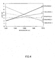
- Figs. 4 and 5 show the loss vs. wavelength characteristic when the phase differences ⁇ 1 and ⁇ 2 of the first and second phase difference elements are 33/4 ⁇ 0 and 21/4 ⁇ 0 respectively. It is to be noted that Fig. 5 shows the loss deviation (departure from linearity).
- Figs. 4 and 5 showing the loss vs. wavelength characteristic, the linearity is maintained despite the increased slope (defined to be the difference in loss between the wavelengths at both ends).
- sequences 1 to 5 correspond to different Faraday rotation angles, that is, to +5dB, +2.5dB, 0dB, -2.5dB and -5dB slopes.
- the linearity of the loss vs. wavelength characteristic is evaluated based on the difference between the straight line connecting the loss values at the wavelengths at both ends of each slope and the loss at each wavelength.
- the linearity of ⁇ 0.2dB is realized in the slope range between +5dB and -5dB.
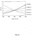
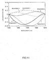
- the background art configuration shown in Fig. 9 has a linearity of +0.2dB to -0.6dB in the same range as shown in Figs. 10 and 11 .
- Fig. 6 shows an example of the slope dependency of the mean insertion loss (insertion loss variation-loss slope) in the configuration of the present invention shown in Fig. 3 .
- the mean insertion loss refers to the mean loss value at each wavelength.
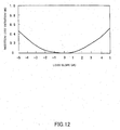
- the mean insertion loss variation is 0.3dB in the slope range between -5dB and +5dB. It is apparent that the variations in the mean insertion loss are suppressed as compared with the background art (0.5dB in Fig. 12 ).
- Fig. 7 shows an example of the linearity of the wavelength slope (linearity-wavelength slope) in the configuration of the present invention shown in Fig. 3 .
- the linearity refers to the linearity when the loss vs. wavelength characteristic is expressed in logarithmic form.
- the linearity is suppressed to 0.2dB or less in the slope range between -5dB and +5dB.
- Fig. 8 shows the relationship between the Faraday rotation angle and the wavelength slope obtained under the same conditions as with Fig. 7 . It is apparent that changing the Faraday rotation angle can continuously vary the wavelength slope.
- the embodiment of the present invention provides a variable optical filter offering an excellent linearity ( ⁇ 0.2dB) over a wide operational slope range (linearity when transmittance is expressed in logarithmic form) thanks to the configuration having a phase difference element at the front and back of a variable Faraday rotator in the optical path and setting the optic axes of the two phase difference elements in different azimuths.
- This enhances the controllable range of wavelengths and makes a wider wavelength region applicable as the range of signal light, thus enabling large volume transmission.
Landscapes
- Physics & Mathematics (AREA)
- Nonlinear Science (AREA)
- Engineering & Computer Science (AREA)
- Power Engineering (AREA)
- General Physics & Mathematics (AREA)
- Optics & Photonics (AREA)
- Optical Modulation, Optical Deflection, Nonlinear Optics, Optical Demodulation, Optical Logic Elements (AREA)
- Polarising Elements (AREA)
Claims (6)
- Variabler optischer Filter, umfassend:einen ersten Polarisator (10);ein erstes Phasendifferenzelement (12), das zur Erzeugung einer Phasendifferenz betriebsfähig ist;einen variablen Faraday-Rotator (14), der so betriebsfähig ist, dass er eine variable Faraday-Rotation vermittelt;ein zweites Phasendifferenzelement (16), das zur Erzeugung einer Phasendifferenz betriebsfähig ist; undeinen zweiten Polarisator (18),wobei die Polarisatoren, der variable Faraday-Rotator und die Phasendifferenzelemente in der vorstehend genannten Anordnung entlang der optischen Achse angeordnet sind;wobei, wenn die Drehrichtung eines Drehwinkels θ des Faraday-Rotators (14) positiv ist, ein durch die übermittelten Azimute der Polarisation der ersten und zweiten Polarisatoren gebildeter Winkel δ auf δ>0 gesetzt wird, wobei der durch die optische Achse des ersten Phasendifferenzelements und das übermittelte Polarisationsazimut des ersten Polarisators gebildete Winkel ϕ1 auf ϕ1<0 gesetzt wird, und wobei der durch die optische Achse des zweiten Phasendifferenzelements und das übermittelte Polarisationsazimut des ersten Polarisators gebildete Winkel ϕ2 auf ϕ2<0 gesetzt wird;wobei die Winkel der durch die optische Achse des ersten Phasendifferenzelements und das übermittelte Polarisationsazimut des ersten Polarisators gebildete Winkel ϕ1 und ϕ2 auf ϕ1 ≠ ϕ2 und ϕ1 - ϕ2 ≠ 90° gesetzt werden;wobei, wenn die durch die ersten und zweiten Phasendifferenzelemente (12, 16) erzeugten Phasendifferenzen entsprechend Δ1 und Δ2 angenommen werden, wenigstens eine der Phasendifferenzen (2n+1 ) λ/4 innerhalb eines vorab gegebenen Übertragungsbands ist, wobei λ eine willkürliche Wellenlänge innerhalb des gegebenen Übertragungsbands ist;und dadurch gekennzeichnet, dass, wenn für mittlere Wellenlänge in dem gegebenen Übertragungsband λ0 angenommen wird, die Phasendifferenz Δ1 des ersten Phasendifferenzelements (12) 13/4λ0≤Δ1≤49/4λ0 ist, wobei die Phasendifferenz Δ2 des zweiten Phasendifferenzelements (16) 13/4λ0≤Δ2≤49/4λ0 ist, und wobei die Abweichungen der mittleren Einfügedämpfung bei der Übertragungsbandbreite von 40 nm und über den Wellenlängenverlauf von -5dB bis +5dB 0,5dB oder weniger betragen.
- Variabler optischer Filter nach Anspruch 1, wobei die Linearität der Dämpfung versus der Wellenlängeneigenschaft bei der Übertragungsbandbreite von 40 nm und über den Wellenlängenverlauf von -5dB bis +5dB 0,2dB oder weniger beträgt.
- Variabler optischer Filter nach Anspruch 2, wobei der variable Bereich des Wellenlängenverlaufs bei der Übertragungsbandbreite von 40 nm und über den Wellenlängenverlauf von -5dB bis +5dB zwischen -6,5dB und +6,5dB liegt.
- Variabler optischer Filter nach Anspruch 1, wobei der Faraday-Rotator folgendes umfasst:ein magnetooptisches Kristall, das in dem optischen Pfad vorgesehen ist;erste Mittel zum Anlegen eines Magnetfelds, die so funktionsfähig sind, dass sie das magnetooptische Kristall magnetisch sättigen; undzweite Mittel zum Anlegen eines Magnetfelds, die so funktionsfähig sind, dass sie ein variables Magnetfeld in die Richtung anlegen, die nicht parallel ist zu der Richtung des durch die ersten Mittel zum Anlegen eines Magnetfelds angelegten Magnetfelds.
- Variabler optischer Filter nach Anspruch 1, wobei die ersten und zweiten Polarisatoren (10, 18) die Form eines Keils aufweisen und aus einem Doppelbrechungsmaterial bestehen, wobei die Polarisatoren so angeordnet sind, dass ihre oberen und unteren Abschnitte in entgegengesetzten Richtungen zueinander ausgerichtet sind, wobei die ersten und zweiten Phasendifferenzelemente (12, 16) die Form einer flachen Platte aufweisen, und wobei die Azimute der optischen Achse des ersten Polarisators und des ersten Phasendifferenzelements bei einer Betrachtung in Richtung der optischen Achse orthogonal zueinander sind.
- Variabler optischer Filter nach Anspruch 1, wobei die ersten und zweiten Phasendifferenzelemente (12, 16) aus unterschiedlichen Materialien gebildet sind, so dass die Brechungsindexabweichung versus den Temperatureigenschaften der beiden Elemente unterschiedliche Vorzeichen aufweisen.
Applications Claiming Priority (3)
| Application Number | Priority Date | Filing Date | Title |
|---|---|---|---|
| JP2002169028A JP4156280B2 (ja) | 2002-06-10 | 2002-06-10 | 可変光学フィルタ |
| JP2002169028 | 2002-06-10 | ||
| PCT/JP2003/007279 WO2003104881A1 (ja) | 2002-06-10 | 2003-06-09 | 可変光学フィルタ |
Publications (3)
| Publication Number | Publication Date |
|---|---|
| EP1515180A1 EP1515180A1 (de) | 2005-03-16 |
| EP1515180A4 EP1515180A4 (de) | 2008-07-02 |
| EP1515180B1 true EP1515180B1 (de) | 2015-08-12 |
Family
ID=29727713
Family Applications (1)
| Application Number | Title | Priority Date | Filing Date |
|---|---|---|---|
| EP03736103.7A Expired - Lifetime EP1515180B1 (de) | 2002-06-10 | 2003-06-09 | Variables optisches filter |
Country Status (4)
| Country | Link |
|---|---|
| US (1) | US7050216B2 (de) |
| EP (1) | EP1515180B1 (de) |
| JP (1) | JP4156280B2 (de) |
| WO (1) | WO2003104881A1 (de) |
Family Cites Families (3)
| Publication number | Priority date | Publication date | Assignee | Title |
|---|---|---|---|---|
| JPH06130339A (ja) * | 1992-10-16 | 1994-05-13 | Fujitsu Ltd | チューナブル光学フィルタ |
| JP3779054B2 (ja) * | 1998-01-23 | 2006-05-24 | 富士通株式会社 | 可変光学フィルタ |
| JP2003121807A (ja) * | 2001-10-12 | 2003-04-23 | Fujitsu Ltd | 可変偏光面回転子およびそれを用いた光デバイス |
-
2002
- 2002-06-10 JP JP2002169028A patent/JP4156280B2/ja not_active Expired - Fee Related
-
2003
- 2003-06-09 EP EP03736103.7A patent/EP1515180B1/de not_active Expired - Lifetime
- 2003-06-09 WO PCT/JP2003/007279 patent/WO2003104881A1/ja not_active Ceased
-
2004
- 2004-12-10 US US11/009,991 patent/US7050216B2/en not_active Expired - Fee Related
Also Published As
| Publication number | Publication date |
|---|---|
| US7050216B2 (en) | 2006-05-23 |
| EP1515180A1 (de) | 2005-03-16 |
| US20050134954A1 (en) | 2005-06-23 |
| EP1515180A4 (de) | 2008-07-02 |
| JP4156280B2 (ja) | 2008-09-24 |
| JP2004013008A (ja) | 2004-01-15 |
| WO2003104881A1 (ja) | 2003-12-18 |
Similar Documents
| Publication | Publication Date | Title |
|---|---|---|
| JP3779054B2 (ja) | 可変光学フィルタ | |
| JP3660402B2 (ja) | 光フィルタ | |
| US6429962B1 (en) | Dynamic gain equalizer for optical amplifiers | |
| EP1174754B1 (de) | Optisches Dämpfungsglied | |
| US6718082B2 (en) | Solid-State optical wavelength switches | |
| EP0289948A1 (de) | Einrichtung zur Polarisationssteuerung | |
| CN1181636C (zh) | 控制输出响应的斜率的方法和系统 | |
| US6876480B2 (en) | Farady rotation device and optical device comprising it | |
| US7079320B2 (en) | Bandwidth properties of LC-SLMs for telecommunication applications with particular third compensator | |
| US7050216B2 (en) | Variable optical filter | |
| US6535324B1 (en) | Bi-directional wavelength-selective optical data apparatus | |
| EP2185968B1 (de) | Optisches filter | |
| JPH06130339A (ja) | チューナブル光学フィルタ | |
| US6728463B2 (en) | Optical attenuator using multi-mode interference | |
| JP3881505B2 (ja) | ファラデー回転装置及びそれを用いた光デバイス | |
| US20020110346A1 (en) | Optical component and optical component module | |
| JP3486091B2 (ja) | 光サーキュレータ | |
| JP2839042B2 (ja) | 光アイソレータ | |
| US20050025447A1 (en) | Multichannel optical attenuator for multiplexed signal | |
| WO2010130281A1 (en) | Optical filter arrangement | |
| JP3881532B2 (ja) | 可変光アッテネータ | |
| JP2001091901A (ja) | 可変光減衰器 | |
| JP2002156604A (ja) | 光アイソレータモジュール |
Legal Events
| Date | Code | Title | Description |
|---|---|---|---|
| PUAI | Public reference made under article 153(3) epc to a published international application that has entered the european phase |
Free format text: ORIGINAL CODE: 0009012 |
|
| 17P | Request for examination filed |
Effective date: 20041216 |
|
| AK | Designated contracting states |
Kind code of ref document: A1 Designated state(s): AT BE BG CH CY CZ DE DK EE ES FI FR GB GR HU IE IT LI LU MC NL PT RO SE SI SK TR |
|
| AX | Request for extension of the european patent |
Extension state: AL LT LV MK |
|
| A4 | Supplementary search report drawn up and despatched |
Effective date: 20080530 |
|
| 17Q | First examination report despatched |
Effective date: 20091111 |
|
| RAP1 | Party data changed (applicant data changed or rights of an application transferred) |
Owner name: FDK CORPORATION |
|
| GRAP | Despatch of communication of intention to grant a patent |
Free format text: ORIGINAL CODE: EPIDOSNIGR1 |
|
| INTG | Intention to grant announced |
Effective date: 20150309 |
|
| RAP1 | Party data changed (applicant data changed or rights of an application transferred) |
Owner name: KOHOKU KOGYO CO., LTD. |
|
| GRAS | Grant fee paid |
Free format text: ORIGINAL CODE: EPIDOSNIGR3 |
|
| GRAA | (expected) grant |
Free format text: ORIGINAL CODE: 0009210 |
|
| AK | Designated contracting states |
Kind code of ref document: B1 Designated state(s): AT BE BG CH CY CZ DE DK EE ES FI FR GB GR HU IE IT LI LU MC NL PT RO SE SI SK TR |
|
| REG | Reference to a national code |
Ref country code: GB Ref legal event code: FG4D |
|
| REG | Reference to a national code |
Ref country code: CH Ref legal event code: EP |
|
| REG | Reference to a national code |
Ref country code: AT Ref legal event code: REF Ref document number: 742662 Country of ref document: AT Kind code of ref document: T Effective date: 20150815 |
|
| REG | Reference to a national code |
Ref country code: IE Ref legal event code: FG4D |
|
| REG | Reference to a national code |
Ref country code: DE Ref legal event code: R096 Ref document number: 60347910 Country of ref document: DE |
|
| REG | Reference to a national code |
Ref country code: AT Ref legal event code: MK05 Ref document number: 742662 Country of ref document: AT Kind code of ref document: T Effective date: 20150812 |
|
| REG | Reference to a national code |
Ref country code: NL Ref legal event code: MP Effective date: 20150812 |
|
| PG25 | Lapsed in a contracting state [announced via postgrant information from national office to epo] |
Ref country code: GR Free format text: LAPSE BECAUSE OF FAILURE TO SUBMIT A TRANSLATION OF THE DESCRIPTION OR TO PAY THE FEE WITHIN THE PRESCRIBED TIME-LIMIT Effective date: 20151113 Ref country code: FI Free format text: LAPSE BECAUSE OF FAILURE TO SUBMIT A TRANSLATION OF THE DESCRIPTION OR TO PAY THE FEE WITHIN THE PRESCRIBED TIME-LIMIT Effective date: 20150812 |
|
| PG25 | Lapsed in a contracting state [announced via postgrant information from national office to epo] |
Ref country code: AT Free format text: LAPSE BECAUSE OF FAILURE TO SUBMIT A TRANSLATION OF THE DESCRIPTION OR TO PAY THE FEE WITHIN THE PRESCRIBED TIME-LIMIT Effective date: 20150812 Ref country code: SE Free format text: LAPSE BECAUSE OF FAILURE TO SUBMIT A TRANSLATION OF THE DESCRIPTION OR TO PAY THE FEE WITHIN THE PRESCRIBED TIME-LIMIT Effective date: 20150812 Ref country code: PT Free format text: LAPSE BECAUSE OF FAILURE TO SUBMIT A TRANSLATION OF THE DESCRIPTION OR TO PAY THE FEE WITHIN THE PRESCRIBED TIME-LIMIT Effective date: 20151214 Ref country code: ES Free format text: LAPSE BECAUSE OF FAILURE TO SUBMIT A TRANSLATION OF THE DESCRIPTION OR TO PAY THE FEE WITHIN THE PRESCRIBED TIME-LIMIT Effective date: 20150812 |
|
| PG25 | Lapsed in a contracting state [announced via postgrant information from national office to epo] |
Ref country code: NL Free format text: LAPSE BECAUSE OF FAILURE TO SUBMIT A TRANSLATION OF THE DESCRIPTION OR TO PAY THE FEE WITHIN THE PRESCRIBED TIME-LIMIT Effective date: 20150812 |
|
| PG25 | Lapsed in a contracting state [announced via postgrant information from national office to epo] |
Ref country code: DK Free format text: LAPSE BECAUSE OF FAILURE TO SUBMIT A TRANSLATION OF THE DESCRIPTION OR TO PAY THE FEE WITHIN THE PRESCRIBED TIME-LIMIT Effective date: 20150812 Ref country code: SK Free format text: LAPSE BECAUSE OF FAILURE TO SUBMIT A TRANSLATION OF THE DESCRIPTION OR TO PAY THE FEE WITHIN THE PRESCRIBED TIME-LIMIT Effective date: 20150812 Ref country code: IT Free format text: LAPSE BECAUSE OF FAILURE TO SUBMIT A TRANSLATION OF THE DESCRIPTION OR TO PAY THE FEE WITHIN THE PRESCRIBED TIME-LIMIT Effective date: 20150812 Ref country code: CZ Free format text: LAPSE BECAUSE OF FAILURE TO SUBMIT A TRANSLATION OF THE DESCRIPTION OR TO PAY THE FEE WITHIN THE PRESCRIBED TIME-LIMIT Effective date: 20150812 Ref country code: EE Free format text: LAPSE BECAUSE OF FAILURE TO SUBMIT A TRANSLATION OF THE DESCRIPTION OR TO PAY THE FEE WITHIN THE PRESCRIBED TIME-LIMIT Effective date: 20150812 |
|
| REG | Reference to a national code |
Ref country code: DE Ref legal event code: R097 Ref document number: 60347910 Country of ref document: DE |
|
| REG | Reference to a national code |
Ref country code: DE Ref legal event code: R082 Ref document number: 60347910 Country of ref document: DE Representative=s name: HERNANDEZ, YORCK, DIPL.-ING., DE |
|
| PG25 | Lapsed in a contracting state [announced via postgrant information from national office to epo] |
Ref country code: RO Free format text: LAPSE BECAUSE OF FAILURE TO SUBMIT A TRANSLATION OF THE DESCRIPTION OR TO PAY THE FEE WITHIN THE PRESCRIBED TIME-LIMIT Effective date: 20150812 |
|
| PLBE | No opposition filed within time limit |
Free format text: ORIGINAL CODE: 0009261 |
|
| STAA | Information on the status of an ep patent application or granted ep patent |
Free format text: STATUS: NO OPPOSITION FILED WITHIN TIME LIMIT |
|
| 26N | No opposition filed |
Effective date: 20160513 |
|
| PG25 | Lapsed in a contracting state [announced via postgrant information from national office to epo] |
Ref country code: SI Free format text: LAPSE BECAUSE OF FAILURE TO SUBMIT A TRANSLATION OF THE DESCRIPTION OR TO PAY THE FEE WITHIN THE PRESCRIBED TIME-LIMIT Effective date: 20150812 |
|
| PG25 | Lapsed in a contracting state [announced via postgrant information from national office to epo] |
Ref country code: BE Free format text: LAPSE BECAUSE OF FAILURE TO SUBMIT A TRANSLATION OF THE DESCRIPTION OR TO PAY THE FEE WITHIN THE PRESCRIBED TIME-LIMIT Effective date: 20150812 |
|
| REG | Reference to a national code |
Ref country code: DE Ref legal event code: R119 Ref document number: 60347910 Country of ref document: DE |
|
| PG25 | Lapsed in a contracting state [announced via postgrant information from national office to epo] |
Ref country code: MC Free format text: LAPSE BECAUSE OF FAILURE TO SUBMIT A TRANSLATION OF THE DESCRIPTION OR TO PAY THE FEE WITHIN THE PRESCRIBED TIME-LIMIT Effective date: 20150812 |
|
| REG | Reference to a national code |
Ref country code: CH Ref legal event code: PL |
|
| GBPC | Gb: european patent ceased through non-payment of renewal fee |
Effective date: 20160609 |
|
| REG | Reference to a national code |
Ref country code: IE Ref legal event code: MM4A |
|
| REG | Reference to a national code |
Ref country code: FR Ref legal event code: ST Effective date: 20170228 |
|
| PG25 | Lapsed in a contracting state [announced via postgrant information from national office to epo] |
Ref country code: LI Free format text: LAPSE BECAUSE OF NON-PAYMENT OF DUE FEES Effective date: 20160630 Ref country code: DE Free format text: LAPSE BECAUSE OF NON-PAYMENT OF DUE FEES Effective date: 20170103 Ref country code: FR Free format text: LAPSE BECAUSE OF NON-PAYMENT OF DUE FEES Effective date: 20160630 Ref country code: CH Free format text: LAPSE BECAUSE OF NON-PAYMENT OF DUE FEES Effective date: 20160630 |
|
| PG25 | Lapsed in a contracting state [announced via postgrant information from national office to epo] |
Ref country code: GB Free format text: LAPSE BECAUSE OF NON-PAYMENT OF DUE FEES Effective date: 20160609 Ref country code: IE Free format text: LAPSE BECAUSE OF NON-PAYMENT OF DUE FEES Effective date: 20160609 |
|
| PG25 | Lapsed in a contracting state [announced via postgrant information from national office to epo] |
Ref country code: HU Free format text: LAPSE BECAUSE OF FAILURE TO SUBMIT A TRANSLATION OF THE DESCRIPTION OR TO PAY THE FEE WITHIN THE PRESCRIBED TIME-LIMIT; INVALID AB INITIO Effective date: 20030609 Ref country code: CY Free format text: LAPSE BECAUSE OF FAILURE TO SUBMIT A TRANSLATION OF THE DESCRIPTION OR TO PAY THE FEE WITHIN THE PRESCRIBED TIME-LIMIT Effective date: 20150812 |
|
| PG25 | Lapsed in a contracting state [announced via postgrant information from national office to epo] |
Ref country code: TR Free format text: LAPSE BECAUSE OF FAILURE TO SUBMIT A TRANSLATION OF THE DESCRIPTION OR TO PAY THE FEE WITHIN THE PRESCRIBED TIME-LIMIT Effective date: 20150812 Ref country code: LU Free format text: LAPSE BECAUSE OF NON-PAYMENT OF DUE FEES Effective date: 20160609 |
|
| PG25 | Lapsed in a contracting state [announced via postgrant information from national office to epo] |
Ref country code: BG Free format text: LAPSE BECAUSE OF FAILURE TO SUBMIT A TRANSLATION OF THE DESCRIPTION OR TO PAY THE FEE WITHIN THE PRESCRIBED TIME-LIMIT Effective date: 20150812 |