EP1515065B1 - Système d'entraînement - Google Patents
Système d'entraînement Download PDFInfo
- Publication number
- EP1515065B1 EP1515065B1 EP04019872A EP04019872A EP1515065B1 EP 1515065 B1 EP1515065 B1 EP 1515065B1 EP 04019872 A EP04019872 A EP 04019872A EP 04019872 A EP04019872 A EP 04019872A EP 1515065 B1 EP1515065 B1 EP 1515065B1
- Authority
- EP
- European Patent Office
- Prior art keywords
- drive arrangement
- arrangement according
- rotor
- vibration damper
- electric machine
- Prior art date
- Legal status (The legal status is an assumption and is not a legal conclusion. Google has not performed a legal analysis and makes no representation as to the accuracy of the status listed.)
- Expired - Lifetime
Links
- 238000002485 combustion reaction Methods 0.000 claims description 22
- 230000005540 biological transmission Effects 0.000 claims description 15
- 239000007858 starting material Substances 0.000 claims description 9
- 238000001816 cooling Methods 0.000 claims description 7
- 230000001360 synchronised effect Effects 0.000 claims description 3
- 239000002826 coolant Substances 0.000 claims 1
- 239000004519 grease Substances 0.000 claims 1
- 239000004020 conductor Substances 0.000 description 4
- 125000006850 spacer group Chemical group 0.000 description 4
- 238000013016 damping Methods 0.000 description 3
- 238000010276 construction Methods 0.000 description 2
- 230000008878 coupling Effects 0.000 description 2
- 238000010168 coupling process Methods 0.000 description 2
- 238000005859 coupling reaction Methods 0.000 description 2
- 239000002184 metal Substances 0.000 description 2
- 230000001172 regenerating effect Effects 0.000 description 2
- 230000015572 biosynthetic process Effects 0.000 description 1
- 238000005266 casting Methods 0.000 description 1
- 239000002131 composite material Substances 0.000 description 1
- 239000012809 cooling fluid Substances 0.000 description 1
- 238000011161 development Methods 0.000 description 1
- 230000018109 developmental process Effects 0.000 description 1
- 230000000694 effects Effects 0.000 description 1
- 238000012432 intermediate storage Methods 0.000 description 1
- 239000000463 material Substances 0.000 description 1
Images

Classifications
-
- H—ELECTRICITY
- H02—GENERATION; CONVERSION OR DISTRIBUTION OF ELECTRIC POWER
- H02K—DYNAMO-ELECTRIC MACHINES
- H02K7/00—Arrangements for handling mechanical energy structurally associated with dynamo-electric machines, e.g. structural association with mechanical driving motors or auxiliary dynamo-electric machines
- H02K7/006—Structural association of a motor or generator with the drive train of a motor vehicle
-
- F—MECHANICAL ENGINEERING; LIGHTING; HEATING; WEAPONS; BLASTING
- F16—ENGINEERING ELEMENTS AND UNITS; GENERAL MEASURES FOR PRODUCING AND MAINTAINING EFFECTIVE FUNCTIONING OF MACHINES OR INSTALLATIONS; THERMAL INSULATION IN GENERAL
- F16F—SPRINGS; SHOCK-ABSORBERS; MEANS FOR DAMPING VIBRATION
- F16F15/00—Suppression of vibrations in systems; Means or arrangements for avoiding or reducing out-of-balance forces, e.g. due to motion
- F16F15/10—Suppression of vibrations in rotating systems by making use of members moving with the system
- F16F15/12—Suppression of vibrations in rotating systems by making use of members moving with the system using elastic members or friction-damping members, e.g. between a rotating shaft and a gyratory mass mounted thereon
- F16F15/131—Suppression of vibrations in rotating systems by making use of members moving with the system using elastic members or friction-damping members, e.g. between a rotating shaft and a gyratory mass mounted thereon the rotating system comprising two or more gyratory masses
- F16F15/133—Suppression of vibrations in rotating systems by making use of members moving with the system using elastic members or friction-damping members, e.g. between a rotating shaft and a gyratory mass mounted thereon the rotating system comprising two or more gyratory masses using springs as elastic members, e.g. metallic springs
- F16F15/134—Wound springs
- F16F15/1343—Wound springs characterised by the spring mounting
Definitions
- the invention relates to a drive arrangement according to the preamble of claim 1.
- a drive arrangement is described in DE-A-100 05 996.
- Torsional vibration dampers are well known. These are used, for example, in motor vehicles in order to isolate as much as possible of the torsional vibrations emanating from an internal combustion engine relative to the drive train and thus to increase the ride comfort. In modern vehicles, in particular dual-mass flywheels have prevailed, which in the usable speed range, i. between the idle speed and a maximum speed, due to their low torsional stiffness effectively contribute to vibration damping.
- the basic structure and the operation of a torsional vibration damper are described for example in DE 196 09 043 C1.
- starter generators in the drive train of a motor vehicle, which can be used on the one hand in the engine operating mode for starting the engine and alone or in cooperation with the internal combustion engine to drive the vehicle.
- a starter generator can operate as a generator in internal combustion engine operation of the vehicle.
- the starter generator can be designed as a permanent-magnet synchronous machine which is arranged between the crankshaft of the internal combustion engine and a clutch or a transmission in the drive train of a vehicle.
- the object of the present invention is to provide a compact drive assembly of an electric machine and a torsional vibration damper for a vehicle with an internal combustion engine.
- the spring accumulator of the vibration damper lie on a comparatively large diameter and can be adjusted with respect to a given spring characteristic exactly the respective existing internal combustion engine or drive train.
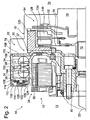
- FIGS 1 and 2 show a drive assembly 10 for a motor vehicle with an electric machine 12 having a stator 14 and a rotor 16 which is rotatably connected via a spacer 18 with the crankshaft 20 of an internal combustion engine 13.
- the electric machine 12 is formed in this example as a permanent magnet multi-phase synchronous machine and acts as a starter generator 12, which has a motor operating mode for starting the engine 22 and for driving the motor vehicle and further a regenerative mode for generating electrical power for a motor vehicle electrical system.
- the electric machine 12 is connected to a conventional vehicle battery, not shown, and possibly to a traction battery.
- the control of the starter generator 12 via a graphically not shown pulse inverter, which receives its switching signals from a control electronics, with a motor control the internal combustion engine or communicates with a parent vehicle control device.
- the drive assembly 10 further includes a torsional vibration damper 22 having an input part 24 with a primary flywheel 26 and connected thereto via a spring accumulator 28 output member 30 with a secondary flywheel 32, which is relatively rotatable to the input part 24.
- the rotor 16 of the electric machine 12 is designed as an external rotor and simultaneously acts as the primary flywheel 26 of the torsional vibration damper 22, wherein the spring accumulator 28 is disposed radially outside and at least partially within the axial extent of the rotor 16.
- the spring accumulator 28 comprises individual, axially adjacent and in each case circumferentially arranged spring sets 34, which are arranged in a fat-filled spring chamber 36.
- the spring chamber 36 is - as this is already known from Zweimasseschwung couplen - divided in the circumferential direction into a plurality of segment-like receiving portions, the spring sets 34 are arranged in the direction of action between each one of the input part 24 and a stop formed by the output member 30 and at a mutual Rotation of the input and output part 24, 30 can be supported on this.
- the rotor 16 has a rotor carrier 37 formed as a deep-drawn part of a sheet material, which together with a first part of the Torsionsschwingungsdämpfers 22 associated with the input part 24 of the Torsionsschwingungsdämpfers 22 also as a deep-drawn part first support member 38 with intermediate storage of a further spacer 40 by a plurality of circumferentially distributed bolts 42nd is attached to the crankshaft 20 of the engine 13.
- the first support part 38 comprises a radial section 39 extending from the axis of rotation A and then merges into a tubular section 41, which is welded to a radially extending section 43 of a second likewise cup-shaped support section 44. In this way, the input part 24 forms with its first and second support part 38, 44, a housing 46 and at the same time the spring chamber of the torsional vibration damper 22 from.
- the rotor carrier 37 of the electric machine 12 is also cup-shaped to form a substantially radial portion 48 and a tubular portion 50, wherein its outer diameter is slightly smaller than the inner diameter of the first support part 38 of the torsional vibration damper 22, which the rotor 16 at least partially axially, more precisely surrounds the tubular portion 50 of the rotor carrier 37 and partially receives in itself.
- the output part 30 destorsionsschvhingungsdämpfers 22 is formed by a turn cup-shaped plate member 52 which is formed substantially within the housing 46 and includes stops for the spring sets 34 in the manner described above.
- an axial extension 54 is formed, which is mounted with a radial bearing 56 on a formed on the input part 24 further axial extension 58.
- a thrust bearing 60 can be arranged in this area.
- the secondary flywheel 32 is formed as a pressure plate 62 of a friction clutch 64 (see FIG. 2) following the torsional vibration damper 22 in the torque transmission path and is formed as a substantially disc-shaped casting.
- the secondary flywheel mass 32 is fixedly connected in the radially inner region thereof to the sheet metal element 52 by rivet connections 66 and provides in its radially outer region a threaded bore 68 for connecting a housing of a friction clutch 64, which with its clutch disk 70 or disks 70 with the input shaft 72 of a subsequent transmission in the transmission 74 is operatively connected.
- a disengaging device 76 is screwed for actuating the friction clutch 64.
- the transmission 74 is provided with a transmission bell 78 fixed to the internal combustion engine (13), the inside of which is shown in FIG. 2, which can receive the electric machine 12, the torsional vibration damper 22 and the clutch 64.
- an intermediate housing may be provided between the engine 13 and the transmission 74.
- the rotor 16 of the electric machine 12 comprises a laminated core 80 accommodated by the tubular section 50 of the rotor carrier 37, on the inner surface of which a plurality of axially aligned permanent magnets 82 are arranged in the circumferential direction. These magnets 82 interact with a coil 88 arranged on a stator yoke 86 via a radial air gap 84.
- the stator 14 comprises a stator carrier 89 which is fixed to the internal combustion engine 13 by a plurality of bolts 90.
- Rotor carrier 37 has for mounting the stator 14 openings 92 through which the bolts 90 can be completely inserted therethrough.
- the stator coils 88 are connected to one another by means of a connection device 94 and connected to the pulse-controlled inverter by way of a terminal box fastened, for example, to the outer wall of the gear bell 78 or of the intermediate housing.
- the interconnecting device 94 comprises in FIG. 1, three radially arranged annular conductor elements 96, which are spaced apart by insulating rings and isolated from each other. However, the conductor elements 96 may also be arranged axially on the stator 14.
- the interconnection device 94 is advantageously arranged radially outside the stator coils 88 and substantially within their axial extent on the side of the stator 14 facing the internal combustion engine 13, because at this position the connection conductors to the terminal box are kept particularly short and electrical power losses can thus be minimized.
- the resulting during operation of the electric machine 12 heat loss is discharged via filled with a cooling fluid cooling channels 98 to a heat exchanger, not shown.
- a present in the internal combustion engine 13 cooling circuit is used in this case together with the starter generator 12, wherein formed in the internal combustion engine 13 cooling channels 100 pass directly into the stator support 89.
- the drive assembly 10 shown in FIG. 2 differs in particular in the construction of the torsional vibration damper 22 with respect to the arrangement shown in Fig. 1.
- a separate input part i. omitted on the first support member 38 of the torsional vibration damper 22 shown in FIG. 1 and instead of the rotor arm 37 of the electric machine 12 as a supporting part of the torsional vibration damper 22 is formed.
- a plurality of radially outwardly projecting webs 102 are welded to the tubular portion 50 of the rotor support 37, on which both sides support elements 104 are riveted to increase the contact surface for the spring sets 34.
- the spring chamber 36 has a radially outer wall portion 106 and end wall portions 108, which are formed by a secondary side arranged on the torsional vibration damper 22 composite secondary plate 110, whereas only a radially inner wall portion of the input part 24, more precisely the tubular portion 50 is formed.
- the housing of the torsional vibration damper 22 is thus essentially formed by the secondary plate 110.
- the planet gears 114 are rotatably arranged by means of plastic snap rings 122 on a radially projecting collar 124 of the rotor carrier 37. Between the collar 124 and the cover plate 120, a plate spring 126 is used to protect against the entry of dirt and before the exit of fat contained in the spring chamber 36 and optionally in the gear chamber 118, which also between the input and output part 24, 30 a Generated base friction for vibration damping.
- the secondary flywheel 32 cup-shaped with an addition to a radially extending mass portion 128 an adjoining axially extending mass portion 130 which comprises the clutch plates 70 designed as a two-disc arrangement friction clutch 64 and the other pressure plates 134, 136 in itself receives.
- the secondary flywheel 32 in this case forms the coupling housing, so that a separate coupling housing is unnecessary.
Landscapes
- Engineering & Computer Science (AREA)
- General Engineering & Computer Science (AREA)
- Power Engineering (AREA)
- Physics & Mathematics (AREA)
- Acoustics & Sound (AREA)
- Aviation & Aerospace Engineering (AREA)
- Mechanical Engineering (AREA)
- Hybrid Electric Vehicles (AREA)
- Connection Of Motors, Electrical Generators, Mechanical Devices, And The Like (AREA)
Claims (25)
- Système d'entraînement (10) pour un véhicule automobile, comprenant- une machine électrique (12) avec un stator (14) et un rotor (16), qui est en liaison active avec un arbre de sortie (20) d'un moteur à combustion interne, et- un amortisseur de vibrations de torsion (22) avec une pièce d'entrée (24) avec une masse d'équilibrage primaire (26) et une pièce de sortie (30) avec une masse d'équilibrage secondaire (32), pièce de sortie reliée à la pièce d'entrée par un accumulateur à ressorts (28) et pouvant tourner par rapport à la pièce d'entrée (24),- dans lequel le rotor (16) de la machine électrique (12) est constitué par un induit extérieur et forme une des masses d'équilibrage (26, 32) de l'amortisseur de vibrations de torsion (22),caractérisé en ce que l'accumulateur à ressorts (28) est disposé radialement à l'extérieur du rotor (16).
- Système d'entraînement selon la revendication 1, caractérisé en ce que l'accumulateur à ressorts (28) est disposé au moins partiellement à l'intérieur de l'extension axiale du rotor (16).
- Système d'entraînement selon la revendication 1 ou 2, caractérisé en ce que l'accumulateur à ressorts (28) est disposé dans une chambre de ressorts (36) et comprend des jeux de ressorts (34) axialement voisins et chaque fois disposés dans la direction périphérique de l'amortisseur de vibrations de torsion (22).
- Système d'entraînement selon l'une quelconque des revendications précédentes, caractérisé en ce que la pièce d'entrée (24) forme le boîtier (46) de l'amortisseur de vibrations de torsion (22) et ce dernier entoure au moins axialement en partie une portion tubulaire (50) d'un support de rotor (37) de la machine électrique (12).
- Système d'entraînement selon l'une quelconque des revendications 1 à 3, caractérisé en ce que la chambre de ressorts (36) présente une région de paroi située radialement à l'extérieur (106) et des régions de paroi du côté frontal (108), qui sont formées par la pièce de sortie (30), et comprend en outre une région de paroi (50) située radialement à l'intérieur et formée par le support de rotor (37).
- Système d'entraînement selon l'une quelconque des revendications précédentes, caractérisé en ce que le support de rotor (37) forme la pièce d'entrée de l'amortisseur de vibrations de torsion (22) et présente des nervures (102) pour l'appui unilatéral des jeux de ressorts (34).
- Système d'entraînement selon l'une quelconque des revendications précédentes, caractérisé en ce que la chambre de ressorts (36) est remplie de graisse.
- Système d'entraînement selon l'une quelconque des revendications précédentes, caractérisé en ce que l'amortisseur de vibrations de torsion (22) comprend un engrenage planétaire (112) avec au moins une roue planétaire (114) montée sur la pièce d'entrée (24), qui est en prise avec une denture (116) formée sur la pièce de sortie (30).
- Système d'entraînement selon la revendication 8, caractérisé en ce que la au moins une roue planétaire (114) est disposée sur un anneau à déclic (122) assemblé à la pièce d'entrée (24).
- Système d'entraînement selon l'une quelconque des revendications précédentes, caractérisé en ce que la pièce de sortie (30) de l'amortisseur de vibrations de torsion (22) est supportée sur la pièce d'entrée (24) de celui-ci.
- Système d'entraînement selon l'une quelconque des revendications précédentes, caractérisé en ce que le rotor (16) de la machine électrique (12) est calé sur l'arbre de sortie (20) du moteur à combustion interne (13).
- Système d'entraînement selon l'une quelconque des revendications précédentes, caractérisé en ce que le rotor (16) de la machine électrique (12) est assemblé à la pièce d'entrée (24) de l'amortisseur de vibrations de torsion (22) et forme la masse d'équilibrage primaire (26).
- Système d'entraînement selon l'une quelconque des revendications précédentes, caractérisé en ce que le stator (14) de la machine électrique (12) est fixé sur le moteur à combustion interne (13).
- Système d'entraînement selon l'une quelconque des revendications précédentes, caractérisé en ce que la machine électrique (12) et le moteur à combustion interne (13) présentent un circuit de refroidissement commun, dans lequel des canaux de refroidissement (100) formés dans le moteur à combustion interne (13) se prolongent immédiatement en canaux de refroidissement (98) d'un support de stator (89).
- Système d'entraînement selon l'une quelconque des revendications précédentes, caractérisé en ce que la machine électrique (12) est constituée par une machine synchrone à excitation permanente.
- Système d'entraînement selon l'une quelconque des revendications précédentes, caractérisé en ce que le stator (14) de la machine électrique (12) présente une pluralité de bobines de stator (88), qui sont connectées les unes aux autres par un dispositif de connexion (94) et qui sont raccordées à une électronique de commande.
- Système d'entraînement selon la revendication 16, caractérisé en ce que le dispositif de connexion (94) est disposé radialement à l'extérieur des bobines de stator (88) et sensiblement à l'intérieur de leur extension axiale sur le côté du stator (14) tourné vers le moteur à combustion interne (13).
- Système d'entraînement selon l'une quelconque des revendications précédentes, caractérisé en ce que la machine électrique (12) forme un générateur de démarrage et présente un mode de fonctionnement en moteur pour le démarrage du moteur à combustion interne (13) et pour l'entraînement du véhicule automobile et présente en outre un mode de fonctionnement en générateur pour la production de puissance électrique pour un réseau électrique à bord du véhicule automobile.
- Système d'entraînement selon l'une quelconque des revendications précédentes, caractérisé en ce que le support de rotor (37) est réalisé en forme de pot et comprend une portion essentiellement radiale (48) et une portion tubulaire (50) se raccordant à celle-ci.
- Système d'entraînement selon l'une quelconque des revendications précédentes, caractérisé en ce que le rotor (16) et l'amortisseur de vibrations de torsion (22) sont fixés sur le moteur à combustion interne (13) au moyen d'éléments de fixation communs (42).
- Système d'entraînement selon l'une quelconque des revendications précédentes, caractérisé en ce que le système d'entraînement (10) comporte un accouplement à friction (64) avec au moins un plateau de pression (62), qui est formé par la masse d'équilibrage secondaire (32) de l'amortisseur de vibrations de torsion (22).
- Système d'entraînement selon la revendication 21, caractérisé en ce que l'accouplement (64) présente au moins un disque d'accouplement (70), qui est en liaison active avec l'arbre d'entrée (72) d'un engrenage (74) suivant dans le chemin de transmission des forces.
- Système d'entraînement selon la revendication 21 ou 22, caractérisé en ce que la masse d'équilibrage secondaire (32) est réalisée en forme de pot et un autre plateau de pression (134, 136) est disposé radialement à l'intérieur de la masse d'équilibrage secondaire (32).
- Système d'entraînement selon la revendication 21 ou 22, caractérisé en ce que la masse d'équilibrage secondaire (32) est réalisée sensiblement en forme de disque et présente un raccord de montage (68) pour le montage d'un accouplement (64).
- Système d'entraînement selon l'une quelconque des revendications précédentes, caractérisé en ce que l'engrenage (74) présente une cloche d'engrenage (78), qui abrite en elle la machine électrique (12), l'amortisseur de vibrations de torsion (22) et l'accouplement (64).
Applications Claiming Priority (2)
| Application Number | Priority Date | Filing Date | Title |
|---|---|---|---|
| DE10342379.6A DE10342379B4 (de) | 2003-09-13 | 2003-09-13 | Antriebsanordnung |
| DE10342379 | 2003-09-13 |
Publications (2)
| Publication Number | Publication Date |
|---|---|
| EP1515065A1 EP1515065A1 (fr) | 2005-03-16 |
| EP1515065B1 true EP1515065B1 (fr) | 2006-06-28 |
Family
ID=34129794
Family Applications (1)
| Application Number | Title | Priority Date | Filing Date |
|---|---|---|---|
| EP04019872A Expired - Lifetime EP1515065B1 (fr) | 2003-09-13 | 2004-08-21 | Système d'entraînement |
Country Status (2)
| Country | Link |
|---|---|
| EP (1) | EP1515065B1 (fr) |
| DE (2) | DE10342379B4 (fr) |
Family Cites Families (4)
| Publication number | Priority date | Publication date | Assignee | Title |
|---|---|---|---|---|
| DE19609043C1 (de) * | 1996-03-08 | 1997-07-24 | Fichtel & Sachs Ag | Schwungmassenvorrichtung mit Eindrückungen als Verzahnung eines Planetengetriebes |
| DE10005996A1 (de) * | 1999-03-02 | 2000-09-07 | Mannesmann Sachs Ag | Drehmomentübertragungseinheit |
| DE10023113A1 (de) * | 2000-02-15 | 2001-08-16 | Mannesmann Sachs Ag | Antriebssystem |
| DE10115504A1 (de) * | 2001-03-29 | 2002-10-10 | Zf Sachs Ag | Mehrfach-Kupplungseinrichtung in Kombination mit einer Torsionsschwingungsdämpferanordnung oder/und einer Elektromaschine |
-
2003
- 2003-09-13 DE DE10342379.6A patent/DE10342379B4/de not_active Expired - Fee Related
-
2004
- 2004-08-21 DE DE502004000870T patent/DE502004000870D1/de not_active Expired - Fee Related
- 2004-08-21 EP EP04019872A patent/EP1515065B1/fr not_active Expired - Lifetime
Also Published As
| Publication number | Publication date |
|---|---|
| DE10342379A1 (de) | 2005-04-07 |
| DE502004000870D1 (de) | 2006-08-10 |
| DE10342379B4 (de) | 2017-07-27 |
| EP1515065A1 (fr) | 2005-03-16 |
Similar Documents
| Publication | Publication Date | Title |
|---|---|---|
| EP0706463B1 (fr) | Systeme d'entrainement pour vehicule hybride | |
| DE10043856B4 (de) | Mehrfach-Antriebseinheit | |
| EP0685122B1 (fr) | Machine electrique comportant au moins un embrayage | |
| EP1086309B1 (fr) | Demarreur-generateur pour automobile | |
| DE10246227B4 (de) | Antriebseinheit, insbesondere für ein Kraftfahrzeug | |
| DE102006034945A1 (de) | Antriebsanordnung für ein Hybridfahrzeug | |
| EP2311680A2 (fr) | Unité d'entraînement pour un véhicule hybride | |
| EP2448092A2 (fr) | Unité d'entraînement avec une machine électrique et un embrayage | |
| DE19954325A1 (de) | Elektrische Maschine zur Integration in einem Antriebsstrang sowie Antriebsstrang | |
| WO2017202413A1 (fr) | Module d'entraînement hybride à transmission intégrée dans un agencement axial | |
| DE102008042636A1 (de) | Drehmomentübertragungseinheit für ein Kraftfahrzeug | |
| DE19905366C2 (de) | Triebstrang | |
| DE19923315B4 (de) | Antriebssystem für ein Kraftfahrzeug | |
| DE102023114395B4 (de) | Hybridmodul | |
| DE10342379B4 (de) | Antriebsanordnung | |
| DE19954372B4 (de) | Antriebsstrang | |
| WO2024245497A1 (fr) | Module hybride | |
| DE10240677A1 (de) | Antriebssystem | |
| DE10217218A1 (de) | Antriebssystem | |
| DE10110903A1 (de) | Elektrische Maschine | |
| DE19917295B4 (de) | Antriebsvorrichtung | |
| DE19943048B4 (de) | Antriebssystem | |
| WO2023116963A1 (fr) | Module hybride à amortisseur intégré au rotor, chaîne cinématique comprenant le module hybride et système de construction du module hybride | |
| DE19964504B4 (de) | Antriebsstrang für ein Kraftfahrzeug mit einem Verbrennungsmotor und einer elektrischen Maschine | |
| DE10017398A1 (de) | Elektrische Maschine |
Legal Events
| Date | Code | Title | Description |
|---|---|---|---|
| PUAI | Public reference made under article 153(3) epc to a published international application that has entered the european phase |
Free format text: ORIGINAL CODE: 0009012 |
|
| AK | Designated contracting states |
Kind code of ref document: A1 Designated state(s): AT BE BG CH CY CZ DE DK EE ES FI FR GB GR HU IE IT LI LU MC NL PL PT RO SE SI SK TR |
|
| AX | Request for extension of the european patent |
Extension state: AL HR LT LV MK |
|
| 17P | Request for examination filed |
Effective date: 20050127 |
|
| GRAP | Despatch of communication of intention to grant a patent |
Free format text: ORIGINAL CODE: EPIDOSNIGR1 |
|
| GRAS | Grant fee paid |
Free format text: ORIGINAL CODE: EPIDOSNIGR3 |
|
| AKX | Designation fees paid |
Designated state(s): DE FR |
|
| GRAA | (expected) grant |
Free format text: ORIGINAL CODE: 0009210 |
|
| AK | Designated contracting states |
Kind code of ref document: B1 Designated state(s): DE FR |
|
| REF | Corresponds to: |
Ref document number: 502004000870 Country of ref document: DE Date of ref document: 20060810 Kind code of ref document: P |
|
| ET | Fr: translation filed | ||
| PLBE | No opposition filed within time limit |
Free format text: ORIGINAL CODE: 0009261 |
|
| STAA | Information on the status of an ep patent application or granted ep patent |
Free format text: STATUS: NO OPPOSITION FILED WITHIN TIME LIMIT |
|
| 26N | No opposition filed |
Effective date: 20070329 |
|
| PGFP | Annual fee paid to national office [announced via postgrant information from national office to epo] |
Ref country code: DE Payment date: 20070816 Year of fee payment: 4 |
|
| PG25 | Lapsed in a contracting state [announced via postgrant information from national office to epo] |
Ref country code: DE Free format text: LAPSE BECAUSE OF NON-PAYMENT OF DUE FEES Effective date: 20090303 |
|
| PGFP | Annual fee paid to national office [announced via postgrant information from national office to epo] |
Ref country code: FR Payment date: 20090814 Year of fee payment: 6 |
|
| REG | Reference to a national code |
Ref country code: FR Ref legal event code: ST Effective date: 20110502 |
|
| PG25 | Lapsed in a contracting state [announced via postgrant information from national office to epo] |
Ref country code: FR Free format text: LAPSE BECAUSE OF NON-PAYMENT OF DUE FEES Effective date: 20100831 |