EP1515038A1 - Kraftstoffsystem für eine Brennkraftmaschine - Google Patents
Kraftstoffsystem für eine Brennkraftmaschine Download PDFInfo
- Publication number
- EP1515038A1 EP1515038A1 EP04017811A EP04017811A EP1515038A1 EP 1515038 A1 EP1515038 A1 EP 1515038A1 EP 04017811 A EP04017811 A EP 04017811A EP 04017811 A EP04017811 A EP 04017811A EP 1515038 A1 EP1515038 A1 EP 1515038A1
- Authority
- EP
- European Patent Office
- Prior art keywords
- fuel
- pressure
- reservoir
- outlet
- fuel system
- Prior art date
- Legal status (The legal status is an assumption and is not a legal conclusion. Google has not performed a legal analysis and makes no representation as to the accuracy of the status listed.)
- Granted
Links
- 239000000446 fuel Substances 0.000 title claims abstract description 162
- 238000002485 combustion reaction Methods 0.000 title claims abstract description 28
- 238000005086 pumping Methods 0.000 claims description 9
- 239000002828 fuel tank Substances 0.000 abstract 1
- 238000010586 diagram Methods 0.000 description 5
- 238000002347 injection Methods 0.000 description 2
- 239000007924 injection Substances 0.000 description 2
- 239000007787 solid Substances 0.000 description 2
- 238000001816 cooling Methods 0.000 description 1
- 238000011161 development Methods 0.000 description 1
- 230000018109 developmental process Effects 0.000 description 1
- 230000001050 lubricating effect Effects 0.000 description 1
- 238000004519 manufacturing process Methods 0.000 description 1
- 230000001105 regulatory effect Effects 0.000 description 1
Images


Classifications
-
- F—MECHANICAL ENGINEERING; LIGHTING; HEATING; WEAPONS; BLASTING
- F02—COMBUSTION ENGINES; HOT-GAS OR COMBUSTION-PRODUCT ENGINE PLANTS
- F02M—SUPPLYING COMBUSTION ENGINES IN GENERAL WITH COMBUSTIBLE MIXTURES OR CONSTITUENTS THEREOF
- F02M37/00—Apparatus or systems for feeding liquid fuel from storage containers to carburettors or fuel-injection apparatus; Arrangements for purifying liquid fuel specially adapted for, or arranged on, internal-combustion engines
- F02M37/04—Feeding by means of driven pumps
- F02M37/08—Feeding by means of driven pumps electrically driven
- F02M37/10—Feeding by means of driven pumps electrically driven submerged in fuel, e.g. in reservoir
Definitions
- the invention relates to a fuel system for a Internal combustion engine, with a reservoir for the Fuel, with a fuel pump coming out of the Reservoir in a pressure area promotes, with a Valve device, which depends on the pressure in Pressure range opens and at least one first outlet has, by the fuel from the pressure range can be derived, and their opening pressure of a Reference pressure depends, and with a return line, through the subsidized but not used fuel in the Reservoir flows back and an additional pumping device drives.
- a fuel system of the type mentioned is from the DE 101 00 700 C1.
- This one describes Fuel injection system, which at a Internal combustion engine with direct fuel injection is used. In this promotes an electric Fuel pump to the fuel from a reservoir a driven by the internal combustion engine high-pressure fuel pump. From there, the fuel gets under high Pressure on to a fuel rail ("rail") promoted, to which several injectors are connected. These inject the fuel directly into one of them each associated combustion chamber.
- the injectors are supplied with more fuel than these in inject the combustion chamber.
- the unused fuel is via a return line in the reservoir returned and serves there to operate a Eductor.
- Object of the present invention is a Fuel system of the type mentioned so to further develop that throughout the operating range of the Internal combustion engine works reliably and one as possible dynamic and exact control of the flow through the Fuel high-pressure pump allows.
- This object is achieved in a fuel system of the beginning mentioned type achieved in that the valve device so is formed that the reference pressure of the pressure in Reservoir is, and that the first outlet of the Valve device is connected to the return line.
- the fuel system according to the invention still has one Another advantage: the fact that the first outlet of the Valve device is connected to the return line, is engaged in all operating conditions of the fuel system Reliable operation of the additional pumping device guaranteed. Especially in push and Low load operation of the internal combustion engine is flowing in the Return line little or no fuel at all back from the injectors to the reservoir what the Operation of the auxiliary pumping device could endanger.
- valve device comprises a valve body which on one side of Pressure in the pressure area and on the other side of the pressure is charged in the reservoir, and in the course its opening movement releases the first outlet.
- valve device may be in the form of a slide valve be built very simple, so that the inventive Fuel system is inexpensive.
- valve device having a second outlet directly connected to the Reservoir is connected.
- the Additional pumping device is fed with too much fuel, resulting in an undesirably high pressure in the return line would lead.
- the opening pressure for the second outlet is higher than that for the first outlet, preferably about 0.2 bar higher than that for the first outlet.
- the valve device is designed as a "cascade valve", which is a relatively constant supply of Ensures additional pumping device.
- the production of the fuel system according to the invention is simplified when the fuel pump and the Valve device are part of a structural unit.
- the structure is further simplified by the assembly in the Reservoir is arranged, as in this case additional lines can be dispensed with.
- a fuel system carries the whole Reference numeral 10. It comprises a tank unit 12, a High pressure fuel pump 14 and a fuel rail 16 ("Rail").
- the tank unit 12 in turn comprises a reservoir 18, in which fuel 20 is stored.
- a reservoir 18 in which fuel 20 is stored.
- an electrical Fuel pump 24 is arranged, which via a filter 26 Fuel from the swirl pot 22 via a check valve 28 in a trained as a pressure line pressure area 30th promotes.
- the pressure region 30 is connected to a connection 32 a valve device 34 connected. This will continue discussed in more detail below.
- the pressure region 30 leads via a further filter 36 the high pressure fuel pump 14.
- This is in the present Embodiment as a 3-cylinder radial piston pump executed and is of a not shown Internal combustion engine directly driven.
- the flow rate of High-pressure fuel pump 14 is passed through a metering valve 38 set.
- the outlet of the metering valve 38 is on the one hand with inlet valves (without reference numerals) of the individual Delivery chambers of the high-pressure fuel pump 14 and on the other hand via a zero feed throttle 40 with a Return line 42 connected.
- the fuel rail 16 is from the high pressure fuel pump 14 fed. In it is the fuel stored under high pressure.
- injectors 44 inject the fuel directly into a respective associated combustion chamber (not shown).
- the injector 44 is also with the Return line 42 connected.
- an optional one Pressure control valve 46 with which the pressure in the fuel rail 16 can be regulated is with this Return line 42 connected.
- the return line 42 leads back to the reservoir 18.
- two Suction jet pumps 48a and 48b fed the one Represent additional pumping device, in the edge and front Everything in the bottom areas of the reservoir 18th are arranged and the fuel from these areas in promote the swirl pot 22.
- an outlet 50 of the valve device 34 with the return line 42 connected As in particular from FIG. 2 is apparent, an outlet 50 of the valve device 34 with the return line 42 connected.
- the valve device 34 as Slider valve is formed. It includes a piston 52, which is slidable in a housing 54th is included. The one side of the piston 52 is over the port 32 is applied to the pressure in the Pressure range 30 prevails. The other side of the piston 52 is pressurized via an opening 56 with that pressure, the prevails in the reservoir 18.
- the outlet 50 is in Housing 54 arranged radially and is in the pressureless state obscured by the piston 52. In this position, the piston 52 pressed by a spring 58.
- the fuel system 10 shown in FIGS. 1 and 2 works as follows:
- the electric Fuel pump 24 is designed so that even at maximum load of the internal combustion engine of the electric fuel pump 24 delivered amount of fuel is higher than the amount of fuel coming from the high pressure fuel pump 14 compressed and into the fuel rail 16 is promoted. In the printing area 30 Therefore, there is a certain increased pressure, the usually between 4.5 and 5.2 bar. This pressure is due to the design of the valve device 34th set:
- Pressure range 30 Regardless of the operating state of the internal combustion engine or the fuel system 10 therefore prevails in Pressure range 30 a comparatively constant pressure.
- the flow rate of the high-pressure fuel pump 14 by a feedforward of the Metering valves 38 can be set accurately and quickly.
- the Compensating for fluctuations in the pressure in the Fuel manifold 16 is therefore fast and reliable possible.
- the electric fuel pump 24 continues with promotes constant delivery in the pressure range 30, the corresponding flow rate from the high-pressure fuel pump 14 but is not retrieved, flows one comparatively high amount of fuel over the Valve device 34 and there via the terminal 32 and the Outlet 50 in the return line 42. This amount of fuel is sufficient, even in such an operating situation the To drive suction jet pumps 48a and 48b.
- the fuel system 10 shown in FIGS. 3 and 4 differs from the above embodiment by the embodiment of the valve device 34, which as "Cascade overflow valve" is formed.
- This includes a second outlet 60 opening in the direction of Piston 52 seen behind the first outlet 50 arranged is and in the swirl pot 22 of the reservoir 18th leads.
- the axial distance of the two outlets 50 and 60 is such that the second outlet 60 from the piston 52 at a pressure in the pressure range 30 is released, the about 0.2 bar above the pressure at which the first Outlet 50 is released.
- the flow rate QF is above the rotational speed N the internal combustion engine applied, which one at the height of Filter 36, ie at the inlet of the high-pressure fuel pump 14 receives.
- the upper dashed curve shows the at previous fuel systems maximum and the lower dashed curve the previous fuel systems minimal flow rate. You can see that this Flow rate above the speed N is almost constant and that the minimum and maximum values are clear differ.
- the two solid lines in FIG. 5 be with the fuel systems 10 of Figures 1 to 4 receive. It can be seen that at low speed N a significantly lower fuel quantity QF than at large Speed N is obtained at the filter 36. This is on it attributed that at low speed N of the High-pressure fuel pump 14 only a small amount of fuel and thus a significant proportion of electric fuel pump 24 funded fuel via the valve device 34 in the reservoir 18th flowing back.
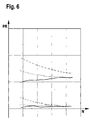
- the pressure PR in the return line 42 is in the Area of the suction jet pumps 48a and 48b over the speed N of the internal combustion engine applied.
- dotted Lines are the maximum and minimum values obtained the fuel system 10 of Figures 1 and 2, by solid lines that of the fuel system 10 of Figures 3 and 4 shown. Dashed lines show the corresponding values in previous fuel systems. you recognizes that the pressure in the fuel systems 10 of the Figures 1 to 4, even at low speeds sufficient high and overall over the speed comparatively is constant.
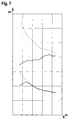
- the pressure PF in the pressure region 30 is above the Applied speed N of the internal combustion engine.
- the dashed curves correspond to the maximum relationship Minimum values in previous ones Fuel systems, the dotted curves at a Fuel system according to Figures 1 and 2, and the solid curves the values in a fuel system according to Figures 3 and 4. It is seen that in the Fuel systems of Figures 1 to 4, the maximum and Minimal values comparatively close together and that the Maximum values significantly lower than previous ones Fuel systems are. Especially the latter lowers the Load on the electric fuel pump 24.
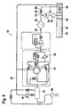
- FIG. 9 shows a further embodiment of a Fuel system 10 shown. Again, that applies Elements and areas that have equivalent functions too Elements and areas of the previous one Embodiments have the same reference numerals wear.
- Valve device 34 designed so that her Opening pressure not from the pressure in the reservoir 18, but depends on the pressure of the spring 58.
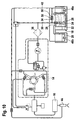
- FIG. 10 A further modified embodiment of a Fuel system 10 is shown in FIG. Here too applies with respect to functionally equivalent elements and areas the above.
- Fuel system 10 is the outlet 50 of Although valve means 34 with the return line 42nd connected, the opening pressure of the valve device 34 depends in contrast to the embodiments of Figures 1 to 4, however, essentially from the pressure in this Return line 42 from.
Landscapes
- Engineering & Computer Science (AREA)
- Chemical & Material Sciences (AREA)
- Combustion & Propulsion (AREA)
- Mechanical Engineering (AREA)
- General Engineering & Computer Science (AREA)
- Fuel-Injection Apparatus (AREA)
Abstract
Description
- Figur 1
- eine schematische Darstellung eines ersten Ausführungsbeispiels eines Kraftstoffsystems;
- Figur 2
- eine vergrößerte Darstellung eines Vorratsbehälters des Kraftstoffsystems von Figur 1;
- Figur 3
- eine Darstellung ähnlich Figur 1 eines zweiten Ausführungsbeispiels eines Kraftstoffsystems;
- Figur 4
- eine Darstellung ähnlich Figur 2 des Vorratsbehälters des Kraftstoffsystems von Figur 3;
- Figur 5
- ein Diagramm, in dem eine Fördermenge einer Kraftstoffpumpe der Kraftstoffsysteme der Figuren 1 bis 4 über der Drehzahl der Brennkraftmaschine aufgetragen ist;
- Figur 6
- ein Diagramm, in dem ein Druck in einer Rücklaufleitung der Kraftstoffsysteme der Figuren 1 bis 4 über der Drehzahl der Brennkraftmaschine aufgetragen ist;
- Figur 7
- ein Diagramm, in dem ein Speisedruck einer Saugstrahlpumpe der Kraftstoffsysteme der Figuren 1 bis 4 über der Drehzahl der Brennkraftmaschine aufgetragen ist;
- Figur 8
- ein Diagramm, in dem der Förderdruck der Kraftstoffpumpe der Kraftstoffsysteme der Figuren 1 bis 4 über der Drehzahl aufgetragen ist;
- Figur 9
- eine schematische Darstellung einer weiteren Ausführungsform eines Kraftstoffsystems; und
- Figur 10
- eine schematische Darstellung einer nochmals abgewandelten Ausführungsform eines Kraftstoffsystems.
Claims (6)
- Kraftstoffsystem (10) für eine Brennkraftmaschine, mit einem Vorratsbehälter (18) für den Kraftstoff, mit einer Kraftstoffpumpe (24), die aus dem Vorratsbehälter (18) in einen Druckbereich (30) fördert, mit einer Ventileinrichtung (34), welche abhängig vom Druck im Druckbereich (30) öffnet und mindestens einen ersten Auslass (50) aufweist, durch den Kraftstoff aus dem Druckbereich (30) abgeleitet werden kann, und deren Öffnungsdruck von einem Referenzdruck abhängt, und mit einer Rücklaufleitung (42), durch die geförderter, aber nicht verwendeter Kraftstoff in den Vorratsbehälter (18) zurückströmt und eine Zusatzpumpeinrichtung (48) antreibt, dadurch gekennzeichnet, dass die Ventileinrichtung (34) so ausgebildet ist, dass der Referenzdruck der Druck im Vorratsbehälter (18) ist, und dass der erste Auslass (50) der Ventileinrichtung (34) mit der Rücklaufleitung (42) verbunden ist.
- Kraftstoffsystem (10) nach Anspruch 1, dadurch gekennzeichnet, dass die Ventileinrichtung (34) einen Ventilkörper (52) umfasst, der auf der einen Seite vom Druck im Druckbereich (30) und auf der anderen Seite vom Druck im Vorratsbehälter (18) beaufschlagt wird, und der im Verlauf seiner Öffnungsbewegung den ersten Auslass (50) freigibt.
- Kraftstoffsystem (10) nach Anspruch 2, dadurch gekennzeichnet, dass die Ventileinrichtung (34) einen zweiten Auslass (60) aufweist, der direkt mit dem Vorratsbehälter (18) verbunden ist.
- Kraftstoffsystem (10) nach Anspruch 3, dadurch gekennzeichnet, dass der Öffnungsdruck für den zweiten Auslass (60) höher ist als jener für den ersten Auslass (50), vorzugsweise ungefähr 0,2 bar höher als jener für den ersten Auslass (50).
- Kraftstoffsystem (10) nach einem der vorhergehenden Ansprüche, dadurch gekennzeichnet, dass die Kraftstoffpumpe (24) und die Ventileinrichtung (34) Teil einer Baueinheit (35) sind.
- Kraftstoffsystem (10) nach Anspruch 5, dadurch gekennzeichnet, dass die Baueinheit (35) im Vorratsbehälter (18) angeordnet ist.
Applications Claiming Priority (2)
| Application Number | Priority Date | Filing Date | Title |
|---|---|---|---|
| DE2003141948 DE10341948A1 (de) | 2003-09-11 | 2003-09-11 | Kraftstoffsystem für eine Brennkraftmaschine |
| DE10341948 | 2003-09-11 |
Publications (2)
| Publication Number | Publication Date |
|---|---|
| EP1515038A1 true EP1515038A1 (de) | 2005-03-16 |
| EP1515038B1 EP1515038B1 (de) | 2010-02-24 |
Family
ID=34129752
Family Applications (1)
| Application Number | Title | Priority Date | Filing Date |
|---|---|---|---|
| EP20040017811 Expired - Lifetime EP1515038B1 (de) | 2003-09-11 | 2004-07-28 | Kraftstoffsystem für eine Brennkraftmaschine |
Country Status (2)
| Country | Link |
|---|---|
| EP (1) | EP1515038B1 (de) |
| DE (2) | DE10341948A1 (de) |
Citations (3)
| Publication number | Priority date | Publication date | Assignee | Title |
|---|---|---|---|---|
| DE19522512A1 (de) * | 1994-06-21 | 1996-02-01 | Walbro Corp | Kraftstoffzuführanlage mit Akkumulator |
| US6345608B1 (en) * | 1998-07-29 | 2002-02-12 | Robert Bosch Gmbh | Fuel supply system for an internal combustion engine |
| US20030111050A1 (en) * | 2001-01-10 | 2003-06-19 | Peter Schueler | Fuel-injection system comprising pressure regulation in the return line |
-
2003
- 2003-09-11 DE DE2003141948 patent/DE10341948A1/de not_active Withdrawn
-
2004
- 2004-07-28 EP EP20040017811 patent/EP1515038B1/de not_active Expired - Lifetime
- 2004-07-28 DE DE200450010799 patent/DE502004010799D1/de not_active Expired - Lifetime
Patent Citations (3)
| Publication number | Priority date | Publication date | Assignee | Title |
|---|---|---|---|---|
| DE19522512A1 (de) * | 1994-06-21 | 1996-02-01 | Walbro Corp | Kraftstoffzuführanlage mit Akkumulator |
| US6345608B1 (en) * | 1998-07-29 | 2002-02-12 | Robert Bosch Gmbh | Fuel supply system for an internal combustion engine |
| US20030111050A1 (en) * | 2001-01-10 | 2003-06-19 | Peter Schueler | Fuel-injection system comprising pressure regulation in the return line |
Also Published As
| Publication number | Publication date |
|---|---|
| DE10341948A1 (de) | 2005-04-21 |
| DE502004010799D1 (de) | 2010-04-08 |
| EP1515038B1 (de) | 2010-02-24 |
Similar Documents
| Publication | Publication Date | Title |
|---|---|---|
| DE4401074B4 (de) | Pumpenanordnung, insbesondere zur Förderung von Kraftstoff aus einem Vorratsbehälter zu einer Brennkraftmaschine | |
| EP2032832B1 (de) | Kraftstoffeinspritzeinrichtung für eine brennkraftmaschine | |
| EP1336043B1 (de) | Kraftstoffeinspritzanlage für brennkraftmaschinen mit verbessertem startverhalten | |
| EP1702157B1 (de) | Kraftstoffeinspritzeinrichtung für eine brennkraftmaschine | |
| EP2670971B1 (de) | Pumpeneinheit für eine hochdruckpumpe | |
| DE102007000855A1 (de) | Kraftstofffördergerät und Speicherkraftstoffeinspritzsystem, das dieses aufweist | |
| EP2449245A1 (de) | Kraftstoffsystem für eine brennkraftmaschine | |
| WO2016075041A2 (de) | Niederdruckregelsystem einer kraftstofffördereinrichtung eines kraftstoffeinspritzsystems sowie ein absteuerventil dazu | |
| DE19541507A1 (de) | Kraftstoffeinspritzeinrichtung für Brennkraftmaschinen | |
| EP2640958B1 (de) | Niederdruckkreislauf für ein kraftstoffeinspritzsystem sowie kraftstoffeinspritzsystem | |
| DE10136399A1 (de) | Kraftstoff-Strahlpumpe für Kraftfahrzeuge | |
| EP1381770A1 (de) | Hochdruck-kraftstoffpumpe für ein kraftstoffsystem einer direkteinspritzenden brennkraftmaschine, kraftstoffsystem sowie brennkraftmaschine | |
| EP1913255B1 (de) | Kraftstoff-fördereinrichtung, insbesondere für eine brennkraftmaschine | |
| EP1357283B1 (de) | Kraftstoffeinspritzeinrichtung für eine Brennkraftmaschine | |
| EP1561028A1 (de) | Kraftstoffhochdruckpumpe mit kugelventil im niederdruck-einlass | |
| WO2007107411A2 (de) | Kraftstoffhochdruckpumpe und kraftstoffeinspritzsystem für eine brennkraftmaschine | |
| DE10129449A1 (de) | Kraftstoffhochdruckpumpe für Brennkraftmaschine mit verbessertem Teillastverhalten | |
| DE10244551A1 (de) | Kraftstoffeinspritzeinrichtung für eine Brennkraftmaschine | |
| WO2003052262A1 (de) | Niederdruckkreislauf für ein speichereinspritzsystem | |
| DE10153189A1 (de) | Kraftstoffpumpe, Kraftstoffsystem, Verfahren zum Betreiben eines Kraftstoffsystems sowie Brennkraftmaschine | |
| DE10139055A1 (de) | Verfahren, Computerprogramm, Steuer- und/oder Regelgerät sowie Kraftstoffsystem für eine Brennkraftmaschine | |
| DE10154133C1 (de) | Kraftstoffsystem | |
| DE102012203724A1 (de) | Kraftstofffördereinrichtung für ein Kraftstoffeinspritzsystem mit einem Überströmventil sowie Überströmventil | |
| EP1515038B1 (de) | Kraftstoffsystem für eine Brennkraftmaschine | |
| DE102006048356A1 (de) | Kraftstoffhochdruckpumpe und Kraftstoffeinspritzsystem für eine Brennkraftmaschine |
Legal Events
| Date | Code | Title | Description |
|---|---|---|---|
| PUAI | Public reference made under article 153(3) epc to a published international application that has entered the european phase |
Free format text: ORIGINAL CODE: 0009012 |
|
| AK | Designated contracting states |
Kind code of ref document: A1 Designated state(s): AT BE BG CH CY CZ DE DK EE ES FI FR GB GR HU IE IT LI LU MC NL PL PT RO SE SI SK TR |
|
| AX | Request for extension of the european patent |
Extension state: AL HR LT LV MK |
|
| 17P | Request for examination filed |
Effective date: 20050916 |
|
| AKX | Designation fees paid |
Designated state(s): DE FR GB IT |
|
| GRAP | Despatch of communication of intention to grant a patent |
Free format text: ORIGINAL CODE: EPIDOSNIGR1 |
|
| GRAS | Grant fee paid |
Free format text: ORIGINAL CODE: EPIDOSNIGR3 |
|
| GRAA | (expected) grant |
Free format text: ORIGINAL CODE: 0009210 |
|
| AK | Designated contracting states |
Kind code of ref document: B1 Designated state(s): DE FR GB IT |
|
| REG | Reference to a national code |
Ref country code: GB Ref legal event code: FG4D Free format text: NOT ENGLISH |
|
| REF | Corresponds to: |
Ref document number: 502004010799 Country of ref document: DE Date of ref document: 20100408 Kind code of ref document: P |
|
| PGFP | Annual fee paid to national office [announced via postgrant information from national office to epo] |
Ref country code: IT Payment date: 20100727 Year of fee payment: 7 |
|
| PGFP | Annual fee paid to national office [announced via postgrant information from national office to epo] |
Ref country code: GB Payment date: 20100726 Year of fee payment: 7 |
|
| PLBE | No opposition filed within time limit |
Free format text: ORIGINAL CODE: 0009261 |
|
| STAA | Information on the status of an ep patent application or granted ep patent |
Free format text: STATUS: NO OPPOSITION FILED WITHIN TIME LIMIT |
|
| 26N | No opposition filed |
Effective date: 20101125 |
|
| GBPC | Gb: european patent ceased through non-payment of renewal fee |
Effective date: 20110728 |
|
| PG25 | Lapsed in a contracting state [announced via postgrant information from national office to epo] |
Ref country code: IT Free format text: LAPSE BECAUSE OF NON-PAYMENT OF DUE FEES Effective date: 20110728 |
|
| PG25 | Lapsed in a contracting state [announced via postgrant information from national office to epo] |
Ref country code: GB Free format text: LAPSE BECAUSE OF NON-PAYMENT OF DUE FEES Effective date: 20110728 |
|
| PGFP | Annual fee paid to national office [announced via postgrant information from national office to epo] |
Ref country code: FR Payment date: 20140724 Year of fee payment: 11 |
|
| REG | Reference to a national code |
Ref country code: FR Ref legal event code: ST Effective date: 20160331 |
|
| PG25 | Lapsed in a contracting state [announced via postgrant information from national office to epo] |
Ref country code: FR Free format text: LAPSE BECAUSE OF NON-PAYMENT OF DUE FEES Effective date: 20150731 |
|
| PGFP | Annual fee paid to national office [announced via postgrant information from national office to epo] |
Ref country code: DE Payment date: 20180928 Year of fee payment: 15 |
|
| REG | Reference to a national code |
Ref country code: DE Ref legal event code: R119 Ref document number: 502004010799 Country of ref document: DE |
|
| PG25 | Lapsed in a contracting state [announced via postgrant information from national office to epo] |
Ref country code: DE Free format text: LAPSE BECAUSE OF NON-PAYMENT OF DUE FEES Effective date: 20200201 |