EP1514979A1 - Manufacturing process for a coving for floor coverings and coving so manufactured - Google Patents
Manufacturing process for a coving for floor coverings and coving so manufactured Download PDFInfo
- Publication number
- EP1514979A1 EP1514979A1 EP04450119A EP04450119A EP1514979A1 EP 1514979 A1 EP1514979 A1 EP 1514979A1 EP 04450119 A EP04450119 A EP 04450119A EP 04450119 A EP04450119 A EP 04450119A EP 1514979 A1 EP1514979 A1 EP 1514979A1
- Authority
- EP
- European Patent Office
- Prior art keywords
- wall
- strip
- edge support
- support wedge
- edge
- Prior art date
- Legal status (The legal status is an assumption and is not a legal conclusion. Google has not performed a legal analysis and makes no representation as to the accuracy of the status listed.)
- Granted
Links
Images
Classifications
-
- E—FIXED CONSTRUCTIONS
- E04—BUILDING
- E04F—FINISHING WORK ON BUILDINGS, e.g. STAIRS, FLOORS
- E04F19/00—Other details of constructional parts for finishing work on buildings
- E04F19/02—Borders; Finishing strips, e.g. beadings; Light coves
- E04F19/04—Borders; Finishing strips, e.g. beadings; Light coves for use between floor or ceiling and wall, e.g. skirtings
- E04F19/045—Hygienic or watertight plinths
-
- E—FIXED CONSTRUCTIONS
- E04—BUILDING
- E04F—FINISHING WORK ON BUILDINGS, e.g. STAIRS, FLOORS
- E04F19/00—Other details of constructional parts for finishing work on buildings
- E04F19/02—Borders; Finishing strips, e.g. beadings; Light coves
- E04F19/04—Borders; Finishing strips, e.g. beadings; Light coves for use between floor or ceiling and wall, e.g. skirtings
- E04F2019/0404—Borders; Finishing strips, e.g. beadings; Light coves for use between floor or ceiling and wall, e.g. skirtings characterised by the material
- E04F2019/0413—Borders; Finishing strips, e.g. beadings; Light coves for use between floor or ceiling and wall, e.g. skirtings characterised by the material of metal
Definitions
- the present invention relates to a process for producing a Wandschwzuges for floor coverings and a subsequently produced Wall skirting.
- floor coverings can be made of PVC, rubber, linoleum or related substances. These pads are on floating screeds or laid on composite screeds. Between the Screed covering and the adjacent masonry it is necessary to have an absolute moisture-proof connection of the top layer to create, which neither by thermal expansion, even by shrinkage in the cold, still by mechanical loads, such as through floor cleaning machines their absolute tightness loses.
- Wipeable floor coverings with wall extensions are mainly used in used public buildings and must be absolutely moisture-proof be educated.
- the care of the floors, which for reasons of hygiene is required on a daily basis which in case of improper handling, the groove of the wall draft can damage.
- chocks By reinforcing the wall lifts in the Bending area by means of chocks, this area is impact and pressure resistant and thus less easily mechanically damaged.
- connection between the flooring that covers the screed and the Masonry is made by a covering strip, which on the one hand glued to the screed and welded to the surface of the screed and on the other hand glued to the masonry, this masonry over a predetermined height is covered by this covering strip.
- This wall siphon is usually made in such a way that in the cleaned Transition area from screed to masonry first the wedge-shaped support body is attached.
- This mostly made of PVC supporting body is in rolls spent to several meters to the construction site and must first before its assembly be brought to linear form. This is usually done by light weight warm up, for example with a hand dryer.
- the support body is cut to the required length and linear aligned with the screed and the wall touching surfaces with Adhesive mass coated and pressed in the appropriate places.
- the covering material is cut into strips on the construction site, coated with adhesive mass, warmed by hand dryer or gas cartridge and glued on the screed, the support body and on the wall to finally welded to the level covering on the screed in the joint become.
- This method requires a high level of craftsmanship, especially around the To align rolls as accurately as possible linear, as in a insufficient alignment the splices easily back from the ground can replace. This can lead to leaks in the topping or there may be places, which at later mechanical Stress can be easily leaking.
- the present invention therefore has as its object, the above To avoid disadvantages and a manufacturing process for a wall-mounted for floor coverings made of PVC, rubber, linoleum or related substances which can be mounted in just two steps on the construction site can and reliably avoids the formation of waves in the edge area.
- the point between the Screed and the masonry through the wall draft with the edge support wedge which has a thickness of up to 8 mm, preferably a thickness of up to 5 mm has, optimally bridged, so that no damage to the coating can occur.
- the factory-prepared wall elevations are in the stretched Condition attached to a support body, which at the same time part of the packaging can be transported to the installation site and can there without further processing be attached directly. Only in the area of wall edges is a Cutting with miter cut required, as in the conventional Procedure too.
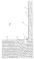
- the Wandschwzug invention is in the figure in the assembled state shown.
- the screed 1 is here as a so-called floating screed trained, that is, he has no firm connection to the concrete floor or to the masonry 2.
- the distance between the screed 1 and the masonry 2 is formed by a continuous gap 3.
- the pad 4 is located on the Screed 1 on.
- a curved at right angles covering strip forms the Wall roll 5 and is connected to the pad 4 by a weld 6.
- To reinforce the bending area 7 of the wall extension 5 against pressure or shock load is t the wall extension 5 in k onvexen B iege Scheme with an edge support wedge 8 coated.
Abstract
Description
Die vorliegende Erfindung betrifft ein Verfahren zur Herstellung eines Wandhochzuges für Bodenbeläge und einen danach hergestellten Wandhochzug. Solche Bodenbeläge können aus PVC, Kautschuk, Linoleum oder artverwandten Stoffen hergestellt sein. Diese Beläge werden auf schwimmenden Estrichen oder auf Verbund-Estrichen verlegt. Zwischen dem Estrichbelag und dem angrenzenden Mauerwerk ist es erforderlich, eine absolut feuchtigkeitsdichte Verbindung des Oberbelages zu schaffen, welche weder durch Wärmeausdehnung, noch durch Schrumpfung bei Kälte, noch durch mechanische Belastungen, etwa durch Bodenreinigungsmaschinen ihre absolute Dichtheit verliert.The present invention relates to a process for producing a Wandschwzuges for floor coverings and a subsequently produced Wall skirting. Such floor coverings can be made of PVC, rubber, linoleum or related substances. These pads are on floating screeds or laid on composite screeds. Between the Screed covering and the adjacent masonry it is necessary to have an absolute moisture-proof connection of the top layer to create, which neither by thermal expansion, even by shrinkage in the cold, still by mechanical loads, such as through floor cleaning machines their absolute tightness loses.
Wischbare Bodenbeläge mit Wandhochzügen werden hauptsächlich in öffentlichen Gebäuden verwendet und müssen absolut feuchtigkeitsdicht ausgebildet sein. Die Pflege der Böden, welche aus hygienischen Gründen täglich erforderlich ist, erfolgt hier grundsätzlich mit Reinigungsmaschinen, welche bei unsachgemäßer Handhabung die Hohlkehle des Wandhochzuges beschädigen können. Durch die Verstärkung der Wandhochzüge im Biegebereich mittels Unterlegkeilen, wird dieser Bereich stoß- und druckfester und damit weniger leicht mechanisch beschädigt. Wipeable floor coverings with wall extensions are mainly used in used public buildings and must be absolutely moisture-proof be educated. The care of the floors, which for reasons of hygiene is required on a daily basis which in case of improper handling, the groove of the wall draft can damage. By reinforcing the wall lifts in the Bending area by means of chocks, this area is impact and pressure resistant and thus less easily mechanically damaged.
Die Verbindung zwischen dem Bodenbelag, der den Estrich abdeckt und dem Mauerwerk wird durch einen Belagstreifen hergestellt, welcher einerseits auf dem Estrich geklebt und mit dem Belag des Estrich verschweißt und andererseits mit dem Mauerwerk verklebt wird, wobei dieses Mauerwerk über eine vorbestimmte Höhe von diesem Belagstreifen überdeckt wird.The connection between the flooring that covers the screed and the Masonry is made by a covering strip, which on the one hand glued to the screed and welded to the surface of the screed and on the other hand glued to the masonry, this masonry over a predetermined height is covered by this covering strip.
Da besonders der Übergangsbereich von Estrich zu Mauerwerk, welcher bei schwimmenden Estrichen eine Dehnungsfuge z.B. aus Styropor aufweist, eine Schwachstelle insbesondere für mechanische Beschädigungen darstellt, wird in diesem Bereich der Belagstreifen auf seiner Rückseite durch einen durchgehenden keilförmigen Stützkörper unterstützt. Damit können stoßartige Belastungen in diesem Bereich abgeschwächt und ein Einreißen verhindert werden.Especially the transition area from screed to masonry, which at floating screeds, an expansion joint e.g. made of styrofoam, one Vulnerability, in particular for mechanical damage, is discussed in This area of toppings on its back by a supported by continuous wedge-shaped support body. This can be jerky Reduced stress in this area and prevented tearing become.
Dieser Wandhochzug wird üblicherweise so hergestellt, dass in den gereinigten Übergangsbereich von Estrich zu Mauerwerk zuerst der keilförmige Stützkörper angebracht wird. Dieser meist aus PVC bestehende Stützkörper wird in Rollen zu mehreren Metern zur Baustelle verbracht und muss vor seiner Montage erst auf lineare Form gebracht werden. Üblicherweise geschieht dies durch leichtes anwärmen, beispielsweise mit einem Handföhn.This wall siphon is usually made in such a way that in the cleaned Transition area from screed to masonry first the wedge-shaped support body is attached. This mostly made of PVC supporting body is in rolls spent to several meters to the construction site and must first before its assembly be brought to linear form. This is usually done by light weight warm up, for example with a hand dryer.
Sobald der Stützkörper in der erforderlichen Länge zugeschnitten und linear ausgerichtet ist, werden die den Estrich und die Wand berührenden Flächen mit Klebermasse bestrichen und an die entsprechenden Stellen gepresst. Anschließend wird das Belagsmaterial auf der Baustelle in Streifen geschnitten, mit Klebermasse bestrichen, mittels Handföhn oder Gaskartusche gewärmt und auf dem Estrich, am Stützkörper und an der Wand aufgeklebt, um schließlich mit dem ebenen Belag auf dem Estrich im Stoß verschweißt zu werden. Once the support body is cut to the required length and linear aligned with the screed and the wall touching surfaces with Adhesive mass coated and pressed in the appropriate places. Then the covering material is cut into strips on the construction site, coated with adhesive mass, warmed by hand dryer or gas cartridge and glued on the screed, the support body and on the wall to finally welded to the level covering on the screed in the joint become.
Die herkömmliche Herstellung eines Wandhochzuges besteht aus den folgenden sechs Arbeitsschritten:
- Ablängen des Stützkörpers
- Lineares Ausrichten des Stützkörpers
- Ankleben des Stützkörpers
- Streifenzuschnitt des Belages
- Ankleben des Streifenzuschnitts
- Verschweißen des Wandhochzuges mit dem ebenen Belag.
- Cutting the support body to length
- Linear alignment of the support body
- Gluing the support body
- Strip trim of the covering
- Gluing the strip blank
- Welding the wall draft with the flat surface.
Diese Methode erfordert hohes handwerkliches Geschick, speziell um die Rollenware möglichst exakt linear auszurichten, da sich bei einer ungenügenden Ausrichtung die Klebestellen leicht wieder vom Untergrund ablösen können. Dadurch kann es zu undichten Stellen im Oberbelag kommen oder es können Stellen entstehen, welche bei späterer mechanischer Beanspruchung sehr leicht undicht werden können.This method requires a high level of craftsmanship, especially around the To align rolls as accurately as possible linear, as in a insufficient alignment the splices easily back from the ground can replace. This can lead to leaks in the topping or there may be places, which at later mechanical Stress can be easily leaking.
Ein weiterer Nachteil dieser Herstellung des Wandhochzuges besteht darin, dass es bei ungleichmäßigem Aufkleben des Streifenzuschnitts zur Ausbildung von unschönen Wellen im Kantenbereich kommen kann, welche zudem einem höheren Verschleiß ausgesetzt sind. Mit dieser Methode sind darüber hinaus - abhängig vom Belagsmaterial - lediglich Kantenradien bis minimal 28 mm möglich.Another disadvantage of this production of the wall draft is that that it with uneven sticking of the strip blank for training can come from unsightly waves in the edge area, which also one are exposed to higher wear. With this method are beyond - depending on the covering material - only edge radii up to a minimum of 28 mm possible.
Die vorliegende Erfindung stellt sich daher die Aufgabe, die genannten Nachteile zu vermeiden und ein Herstellungsverfahren für einen Wandhochzug für Bodenbeläge aus PVC, Kautschuk, Linoleum oder artverwandten Stoffen zu schaffen, welcher in nur zwei Arbeitsschritten auf der Baustelle montiert werden kann und zuverlässig die Bildung von Wellen im Kantenbereich vermeidet. The present invention therefore has as its object, the above To avoid disadvantages and a manufacturing process for a wall-mounted for floor coverings made of PVC, rubber, linoleum or related substances which can be mounted in just two steps on the construction site can and reliably avoids the formation of waves in the edge area.
Diese Aufgabe wird dadurch gelöst, dass der Bodenbelag werksseitig zu Streifen zugeschnitten, entlang seiner Längsachse im rechten Winkel gebogen und im äußeren Kantenbereich mit einem Kantenstützmaterial, bevorzugt aus dauerelastischem Kunststoff beschichtet wird. Der solcherart werksseitig vorbereitete Wandhochzug wird auf der Baustelle lediglich auf dem Estrich und an der Wand angeklebt und sodann mit dem ebenen Bodenbelag verschweißt. Eine separate Anbringung eines Stützkörpers entfällt zur Gänze. Weiters entfällt der händische Streifenzuschnitt auf der Baustelle, da ein werksseitiger Streifenzuschnitt s chneller u nd mit h öherer G enauigkeit m aschinell er folgen kann.This object is achieved in that the floor covering at the factory Tailored strip, bent at right angles along its longitudinal axis and in the outer edge region with an edge support material, preferably made of permanently elastic plastic is coated. The factory so Prepared wall draft is on the construction site only on the screed and glued to the wall and then welded to the flat flooring. A separate attachment of a support body is completely eliminated. Furthermore deleted the manual strip cut on the construction site, as a factory Stripe cut s chneller and follow with greater precision m arschinell can.
Mit dem erfindungsgemäßen Wandhochzug wird die Stelle zwischen dem Estrich und dem Mauerwerk durch den Wandhochzug mit dem Kantenstützkeil, welcher eine Stärke von bis zu 8 mm, bevorzugt eine Stärke von bis zu 5 mm aufweist, optimal überbrückt, damit keine Schäden am Belag entstehen können.With the Wandschwzug invention, the point between the Screed and the masonry through the wall draft with the edge support wedge, which has a thickness of up to 8 mm, preferably a thickness of up to 5 mm has, optimally bridged, so that no damage to the coating can occur.
Die solcherart werkseitig vorbereiteten Wandhochzüge werden im gestreckten Zustand an einem Stützkörper befestigt, welcher zugleich Teil der Verpackung sein kann, zur Einbaustelle befördert und können dort ohne weitere Bearbeitung direkt befestigt werden. Lediglich im Bereich von Wandkanten ist eine Ablängung mit Gehrungsschnitt erforderlich, so wie beim herkömmlichen Verfahren auch.The factory-prepared wall elevations are in the stretched Condition attached to a support body, which at the same time part of the packaging can be transported to the installation site and can there without further processing be attached directly. Only in the area of wall edges is a Cutting with miter cut required, as in the conventional Procedure too.
Mit den erfindungsgemäßen Wandhochzügen wird die Lebensdauer der Wandhochzüge um ein vielfaches verlängert. Ein weiterer Vorteil liegt darin, dass etwa 50 % der Arbeitszeit auf der Baustelle entfallen, wodurch der Montagepreis erheblich gesenkt werden kann. Durch die geringere körperliche Anstrengung sind auch positive Auswirkungen auf die Gesundheit der Bodenleger zu erwarten. With the wall extensions of the invention, the life of the Wall extensions extended by a multiple. Another advantage is that about 50% of the working time is spent on the construction site, which makes the Mounting price can be significantly reduced. Due to the lower physical Effort also have positive health effects Floors expected.
Der erfindungsgemäße Wandhochzug ist in der Figur im montierten Zustand
dargestellt. Der Estrich 1 ist hier als sogenannter schwimmender Estrich
ausgebildet, das heißt, er besitzt keine feste Verbindung zum Betonboden oder
zum Mauerwerk 2. Der Abstand zwischen dem Estrich 1 und dem Mauerwerk 2
wird durch einen durchgehenden Spalt 3 gebildet. Der Belag 4 liegt auf dem
Estrich 1 auf. Ein im rechten Winkel gebogener Belagsstreifen bildet den
Wandhochzug 5 und ist mit dem Belag 4 durch eine Schweißnaht 6 verbunden.
Zur Verstärkung des Biegebereiches 7 des Wandhochzugs 5 gegen Druck-
oder Stoßbelastung is t der Wandhochzug 5 im k onvexen B iegebereich mit
einem Kantenstützkeil 8 beschichtet.The Wandschwzug invention is in the figure in the assembled state
shown. The
Claims (10)
Priority Applications (2)
| Application Number | Priority Date | Filing Date | Title |
|---|---|---|---|
| AT04450119T ATE329099T1 (en) | 2003-09-12 | 2004-05-27 | METHOD FOR PRODUCING A WALL FOR FLOORING AND THEREFORE PRODUCED WALL |
| PL04450119T PL1514979T3 (en) | 2003-09-12 | 2004-05-27 | Manufacturing process for a coving for floor coverings and coving so manufactured |
Applications Claiming Priority (2)
| Application Number | Priority Date | Filing Date | Title |
|---|---|---|---|
| AT0062503U AT7316U1 (en) | 2003-09-12 | 2003-09-12 | METHOD FOR PRODUCING A WALL HOIST FOR FLOORING AND A WALL HOIST PRODUCED ACCORDING TO THEREOF |
| AT6252003U | 2003-09-12 |
Publications (2)
| Publication Number | Publication Date |
|---|---|
| EP1514979A1 true EP1514979A1 (en) | 2005-03-16 |
| EP1514979B1 EP1514979B1 (en) | 2006-06-07 |
Family
ID=33314806
Family Applications (1)
| Application Number | Title | Priority Date | Filing Date |
|---|---|---|---|
| EP04450119A Active EP1514979B1 (en) | 2003-09-12 | 2004-05-27 | Manufacturing process for a coving for floor coverings and coving so manufactured |
Country Status (4)
| Country | Link |
|---|---|
| EP (1) | EP1514979B1 (en) |
| AT (2) | AT7316U1 (en) |
| DE (1) | DE502004000693D1 (en) |
| PL (1) | PL1514979T3 (en) |
Cited By (1)
| Publication number | Priority date | Publication date | Assignee | Title |
|---|---|---|---|---|
| EP4350100A1 (en) | 2022-10-07 | 2024-04-10 | Walfred Prossegger | Wall cove for floor coverings and method for producing a wall cove |
Families Citing this family (4)
| Publication number | Priority date | Publication date | Assignee | Title |
|---|---|---|---|---|
| ES2311955T3 (en) | 2005-04-07 | 2009-02-16 | Walfred Prossegger | MATARRINCON FOR THE UNION ZONE OF A ZOCALO. |
| AT12716U1 (en) * | 2011-05-24 | 2012-10-15 | Pro Fil Kunststoff Gmbh | METHOD FOR THE PRODUCTION OF A CORNER CLADDING FOR THE SHOCK AREA OF A WALL HOIST AND CORNER COVERED PRODUCT THEREOF |
| AT13919U1 (en) * | 2013-10-07 | 2014-12-15 | Walfred Prossegger | Device for producing a factory prefabricated Wandhochzuges |
| CH718253A2 (en) | 2021-01-14 | 2022-07-15 | Loser Urs | Plinth with a strip of resilient flooring material and method of making this plinth. |
Citations (2)
| Publication number | Priority date | Publication date | Assignee | Title |
|---|---|---|---|---|
| GB721086A (en) * | 1952-02-15 | 1954-12-29 | Ejner Robert Tjorn | Improvements in and relating to a method for the production of a fashioned piece of linoleum and apparatus for use in carrying out the method |
| US5020985A (en) * | 1989-11-27 | 1991-06-04 | Torres Carlos M | Laminate bending device |
-
2003
- 2003-09-12 AT AT0062503U patent/AT7316U1/en not_active IP Right Cessation
-
2004
- 2004-05-27 PL PL04450119T patent/PL1514979T3/en unknown
- 2004-05-27 DE DE502004000693T patent/DE502004000693D1/en active Active
- 2004-05-27 EP EP04450119A patent/EP1514979B1/en active Active
- 2004-05-27 AT AT04450119T patent/ATE329099T1/en active
Patent Citations (2)
| Publication number | Priority date | Publication date | Assignee | Title |
|---|---|---|---|---|
| GB721086A (en) * | 1952-02-15 | 1954-12-29 | Ejner Robert Tjorn | Improvements in and relating to a method for the production of a fashioned piece of linoleum and apparatus for use in carrying out the method |
| US5020985A (en) * | 1989-11-27 | 1991-06-04 | Torres Carlos M | Laminate bending device |
Cited By (1)
| Publication number | Priority date | Publication date | Assignee | Title |
|---|---|---|---|---|
| EP4350100A1 (en) | 2022-10-07 | 2024-04-10 | Walfred Prossegger | Wall cove for floor coverings and method for producing a wall cove |
Also Published As
| Publication number | Publication date |
|---|---|
| DE502004000693D1 (en) | 2006-07-20 |
| ATE329099T1 (en) | 2006-06-15 |
| AT7316U1 (en) | 2005-01-25 |
| EP1514979B1 (en) | 2006-06-07 |
| PL1514979T3 (en) | 2006-10-31 |
Similar Documents
| Publication | Publication Date | Title |
|---|---|---|
| DE69826389T2 (en) | Prefabricated wooden floor, which is fixed by means of an adhesive layer | |
| DE102007010997A1 (en) | Joint tape for sanitary facilities | |
| DE202008007139U1 (en) | Prefabricated building with wooden beams and integrated heating pipes | |
| WO2013064246A2 (en) | Method for a multi-stage joint protection system for wall elements made of concrete components | |
| DE3527507C2 (en) | ||
| EP1514979A1 (en) | Manufacturing process for a coving for floor coverings and coving so manufactured | |
| DE20314477U1 (en) | Factory-fabricated edge strip for floor coverings, for production of a moisture-tight joint at walls, is bent through a right angle along its longitudinal axis, and is provided with a support wedge | |
| EP2077360B1 (en) | Floor structure with thermal and sound insulation | |
| EP0312488A2 (en) | Method and device to restore a staircase | |
| EP1905911B1 (en) | Seal for watertight concrete cellars | |
| EP2527562B1 (en) | Method for producing a corner covering for the impact area of a wall bonding and corner covering produced according to the method | |
| AT516814B1 (en) | mOlDinG | |
| EP1201848A2 (en) | Sound absorbing supporting web for floor coverings, especially for tile claddings | |
| DE102019101502A1 (en) | Device for sealing between wall and floor surfaces of buildings | |
| EP1538281B1 (en) | Method and prefabricated element for manufacturing a swimming pool with a gutter | |
| AT511373A1 (en) | COMPOSITE CONSTRUCTION FROM A GLASS PANEL AND A FRAME CONSTRUCTION | |
| EP1582651A1 (en) | Lower finishing edge of a composite thermal lining system of a façade | |
| DE19802857C2 (en) | Pre-assembled fillet profile for construction, especially sealing purposes and use of such a profile | |
| DE102021134257A1 (en) | Improved reinforcement fabric and method of using same | |
| EP2543793B1 (en) | Method for producing and laying a floor strip | |
| DE102009019182B4 (en) | sealing system | |
| DE3706804A1 (en) | Slab, in particular floor slab consisting of concrete | |
| WO1998049413A1 (en) | Edge element | |
| DE1509757A1 (en) | Resilient floors and vibrating floors and processes for their manufacture and installation | |
| EP2374988A2 (en) | Movement joint profile and floor construction |
Legal Events
| Date | Code | Title | Description |
|---|---|---|---|
| PUAI | Public reference made under article 153(3) epc to a published international application that has entered the european phase |
Free format text: ORIGINAL CODE: 0009012 |
|
| 17P | Request for examination filed |
Effective date: 20040601 |
|
| AK | Designated contracting states |
Kind code of ref document: A1 Designated state(s): AT BE BG CH CY CZ DE DK EE ES FI FR GB GR HU IE IT LI LU MC NL PL PT RO SE SI SK TR |
|
| AX | Request for extension of the european patent |
Extension state: AL HR LT LV MK |
|
| 17Q | First examination report despatched |
Effective date: 20050601 |
|
| GRAP | Despatch of communication of intention to grant a patent |
Free format text: ORIGINAL CODE: EPIDOSNIGR1 |
|
| AKX | Designation fees paid |
Designated state(s): AT BE BG CH CY CZ DE DK EE ES FI FR GB GR HU IE IT LI LU MC NL PL PT RO SE SI SK TR |
|
| GRAS | Grant fee paid |
Free format text: ORIGINAL CODE: EPIDOSNIGR3 |
|
| GRAA | (expected) grant |
Free format text: ORIGINAL CODE: 0009210 |
|
| AK | Designated contracting states |
Kind code of ref document: B1 Designated state(s): AT BE BG CH CY CZ DE DK EE ES FI FR GB GR HU IE IT LI LU MC NL PL PT RO SE SI SK TR |
|
| PG25 | Lapsed in a contracting state [announced via postgrant information from national office to epo] |
Ref country code: NL Free format text: LAPSE BECAUSE OF FAILURE TO SUBMIT A TRANSLATION OF THE DESCRIPTION OR TO PAY THE FEE WITHIN THE PRESCRIBED TIME-LIMIT Effective date: 20060607 Ref country code: IT Free format text: LAPSE BECAUSE OF FAILURE TO SUBMIT A TRANSLATION OF THE DESCRIPTION OR TO PAY THE FEE WITHIN THE PRESCRIBED TIME-LIMIT;WARNING: LAPSES OF ITALIAN PATENTS WITH EFFECTIVE DATE BEFORE 2007 MAY HAVE OCCURRED AT ANY TIME BEFORE 2007. THE CORRECT EFFECTIVE DATE MAY BE DIFFERENT FROM THE ONE RECORDED. Effective date: 20060607 Ref country code: IE Free format text: LAPSE BECAUSE OF FAILURE TO SUBMIT A TRANSLATION OF THE DESCRIPTION OR TO PAY THE FEE WITHIN THE PRESCRIBED TIME-LIMIT Effective date: 20060607 Ref country code: FI Free format text: LAPSE BECAUSE OF FAILURE TO SUBMIT A TRANSLATION OF THE DESCRIPTION OR TO PAY THE FEE WITHIN THE PRESCRIBED TIME-LIMIT Effective date: 20060607 Ref country code: RO Free format text: LAPSE BECAUSE OF FAILURE TO SUBMIT A TRANSLATION OF THE DESCRIPTION OR TO PAY THE FEE WITHIN THE PRESCRIBED TIME-LIMIT Effective date: 20060607 Ref country code: SI Free format text: LAPSE BECAUSE OF FAILURE TO SUBMIT A TRANSLATION OF THE DESCRIPTION OR TO PAY THE FEE WITHIN THE PRESCRIBED TIME-LIMIT Effective date: 20060607 Ref country code: SK Free format text: LAPSE BECAUSE OF FAILURE TO SUBMIT A TRANSLATION OF THE DESCRIPTION OR TO PAY THE FEE WITHIN THE PRESCRIBED TIME-LIMIT Effective date: 20060607 |
|
| REG | Reference to a national code |
Ref country code: GB Ref legal event code: FG4D Free format text: NOT ENGLISH |
|
| REG | Reference to a national code |
Ref country code: CH Ref legal event code: EP |
|
| REG | Reference to a national code |
Ref country code: IE Ref legal event code: FG4D Free format text: LANGUAGE OF EP DOCUMENT: GERMAN |
|
| GBT | Gb: translation of ep patent filed (gb section 77(6)(a)/1977) |
Effective date: 20060626 |
|
| REF | Corresponds to: |
Ref document number: 502004000693 Country of ref document: DE Date of ref document: 20060720 Kind code of ref document: P |
|
| PG25 | Lapsed in a contracting state [announced via postgrant information from national office to epo] |
Ref country code: DK Free format text: LAPSE BECAUSE OF FAILURE TO SUBMIT A TRANSLATION OF THE DESCRIPTION OR TO PAY THE FEE WITHIN THE PRESCRIBED TIME-LIMIT Effective date: 20060907 Ref country code: SE Free format text: LAPSE BECAUSE OF FAILURE TO SUBMIT A TRANSLATION OF THE DESCRIPTION OR TO PAY THE FEE WITHIN THE PRESCRIBED TIME-LIMIT Effective date: 20060907 |
|
| PG25 | Lapsed in a contracting state [announced via postgrant information from national office to epo] |
Ref country code: ES Free format text: LAPSE BECAUSE OF FAILURE TO SUBMIT A TRANSLATION OF THE DESCRIPTION OR TO PAY THE FEE WITHIN THE PRESCRIBED TIME-LIMIT Effective date: 20060918 |
|
| PG25 | Lapsed in a contracting state [announced via postgrant information from national office to epo] |
Ref country code: PT Free format text: LAPSE BECAUSE OF FAILURE TO SUBMIT A TRANSLATION OF THE DESCRIPTION OR TO PAY THE FEE WITHIN THE PRESCRIBED TIME-LIMIT Effective date: 20061107 |
|
| ET | Fr: translation filed | ||
| NLV1 | Nl: lapsed or annulled due to failure to fulfill the requirements of art. 29p and 29m of the patents act | ||
| REG | Reference to a national code |
Ref country code: HU Ref legal event code: AG4A Ref document number: E000831 Country of ref document: HU |
|
| REG | Reference to a national code |
Ref country code: IE Ref legal event code: FD4D |
|
| PLBE | No opposition filed within time limit |
Free format text: ORIGINAL CODE: 0009261 |
|
| STAA | Information on the status of an ep patent application or granted ep patent |
Free format text: STATUS: NO OPPOSITION FILED WITHIN TIME LIMIT |
|
| 26N | No opposition filed |
Effective date: 20070308 |
|
| BERE | Be: lapsed |
Owner name: PROSSEGGER, KARL Effective date: 20070531 Owner name: PROSSEGGER, WALFRED Effective date: 20070531 |
|
| PG25 | Lapsed in a contracting state [announced via postgrant information from national office to epo] |
Ref country code: MC Free format text: LAPSE BECAUSE OF NON-PAYMENT OF DUE FEES Effective date: 20070531 |
|
| PG25 | Lapsed in a contracting state [announced via postgrant information from national office to epo] |
Ref country code: BE Free format text: LAPSE BECAUSE OF NON-PAYMENT OF DUE FEES Effective date: 20070531 |
|
| PG25 | Lapsed in a contracting state [announced via postgrant information from national office to epo] |
Ref country code: GR Free format text: LAPSE BECAUSE OF FAILURE TO SUBMIT A TRANSLATION OF THE DESCRIPTION OR TO PAY THE FEE WITHIN THE PRESCRIBED TIME-LIMIT Effective date: 20060908 |
|
| PG25 | Lapsed in a contracting state [announced via postgrant information from national office to epo] |
Ref country code: BG Free format text: LAPSE BECAUSE OF FAILURE TO SUBMIT A TRANSLATION OF THE DESCRIPTION OR TO PAY THE FEE WITHIN THE PRESCRIBED TIME-LIMIT Effective date: 20060907 |
|
| PG25 | Lapsed in a contracting state [announced via postgrant information from national office to epo] |
Ref country code: EE Free format text: LAPSE BECAUSE OF FAILURE TO SUBMIT A TRANSLATION OF THE DESCRIPTION OR TO PAY THE FEE WITHIN THE PRESCRIBED TIME-LIMIT Effective date: 20060607 |
|
| PGRI | Patent reinstated in contracting state [announced from national office to epo] |
Ref country code: IT Effective date: 20080601 |
|
| REG | Reference to a national code |
Ref country code: CH Ref legal event code: PL |
|
| PG25 | Lapsed in a contracting state [announced via postgrant information from national office to epo] |
Ref country code: LI Free format text: LAPSE BECAUSE OF NON-PAYMENT OF DUE FEES Effective date: 20080531 Ref country code: CH Free format text: LAPSE BECAUSE OF NON-PAYMENT OF DUE FEES Effective date: 20080531 |
|
| PG25 | Lapsed in a contracting state [announced via postgrant information from national office to epo] |
Ref country code: LU Free format text: LAPSE BECAUSE OF NON-PAYMENT OF DUE FEES Effective date: 20070527 Ref country code: CY Free format text: LAPSE BECAUSE OF FAILURE TO SUBMIT A TRANSLATION OF THE DESCRIPTION OR TO PAY THE FEE WITHIN THE PRESCRIBED TIME-LIMIT Effective date: 20060607 |
|
| PG25 | Lapsed in a contracting state [announced via postgrant information from national office to epo] |
Ref country code: TR Free format text: LAPSE BECAUSE OF FAILURE TO SUBMIT A TRANSLATION OF THE DESCRIPTION OR TO PAY THE FEE WITHIN THE PRESCRIBED TIME-LIMIT Effective date: 20060607 |
|
| PGFP | Annual fee paid to national office [announced via postgrant information from national office to epo] |
Ref country code: HU Payment date: 20100527 Year of fee payment: 7 |
|
| PG25 | Lapsed in a contracting state [announced via postgrant information from national office to epo] |
Ref country code: HU Free format text: LAPSE BECAUSE OF NON-PAYMENT OF DUE FEES Effective date: 20110528 |
|
| PGFP | Annual fee paid to national office [announced via postgrant information from national office to epo] |
Ref country code: CZ Payment date: 20140519 Year of fee payment: 11 |
|
| PGFP | Annual fee paid to national office [announced via postgrant information from national office to epo] |
Ref country code: PL Payment date: 20140515 Year of fee payment: 11 |
|
| PG25 | Lapsed in a contracting state [announced via postgrant information from national office to epo] |
Ref country code: CZ Free format text: LAPSE BECAUSE OF NON-PAYMENT OF DUE FEES Effective date: 20150527 |
|
| REG | Reference to a national code |
Ref country code: FR Ref legal event code: PLFP Year of fee payment: 13 |
|
| PG25 | Lapsed in a contracting state [announced via postgrant information from national office to epo] |
Ref country code: PL Free format text: LAPSE BECAUSE OF NON-PAYMENT OF DUE FEES Effective date: 20150527 |
|
| REG | Reference to a national code |
Ref country code: FR Ref legal event code: PLFP Year of fee payment: 14 |
|
| REG | Reference to a national code |
Ref country code: FR Ref legal event code: PLFP Year of fee payment: 15 |
|
| PGFP | Annual fee paid to national office [announced via postgrant information from national office to epo] |
Ref country code: IT Payment date: 20230531 Year of fee payment: 20 Ref country code: FR Payment date: 20230517 Year of fee payment: 20 Ref country code: DE Payment date: 20230519 Year of fee payment: 20 |
|
| PGFP | Annual fee paid to national office [announced via postgrant information from national office to epo] |
Ref country code: AT Payment date: 20230516 Year of fee payment: 20 |
|
| PGFP | Annual fee paid to national office [announced via postgrant information from national office to epo] |
Ref country code: GB Payment date: 20230522 Year of fee payment: 20 |