EP1514875A1 - Isoelektrische Fokusierung von Proteinen mit sequentiellen und gegenläufigen Wanderwellen in Gelelektrophorese - Google Patents
Isoelektrische Fokusierung von Proteinen mit sequentiellen und gegenläufigen Wanderwellen in Gelelektrophorese Download PDFInfo
- Publication number
- EP1514875A1 EP1514875A1 EP04013740A EP04013740A EP1514875A1 EP 1514875 A1 EP1514875 A1 EP 1514875A1 EP 04013740 A EP04013740 A EP 04013740A EP 04013740 A EP04013740 A EP 04013740A EP 1514875 A1 EP1514875 A1 EP 1514875A1
- Authority
- EP
- European Patent Office
- Prior art keywords
- grid
- strip
- electrode
- cell
- signal
- Prior art date
- Legal status (The legal status is an assumption and is not a legal conclusion. Google has not performed a legal analysis and makes no representation as to the accuracy of the status listed.)
- Granted
Links
Images



Classifications
-
- G—PHYSICS
- G01—MEASURING; TESTING
- G01N—INVESTIGATING OR ANALYSING MATERIALS BY DETERMINING THEIR CHEMICAL OR PHYSICAL PROPERTIES
- G01N27/00—Investigating or analysing materials by the use of electric, electrochemical, or magnetic means
- G01N27/26—Investigating or analysing materials by the use of electric, electrochemical, or magnetic means by investigating electrochemical variables; by using electrolysis or electrophoresis
- G01N27/416—Systems
- G01N27/447—Systems using electrophoresis
- G01N27/44756—Apparatus specially adapted therefor
- G01N27/44795—Isoelectric focusing
-
- G—PHYSICS
- G01—MEASURING; TESTING
- G01N—INVESTIGATING OR ANALYSING MATERIALS BY DETERMINING THEIR CHEMICAL OR PHYSICAL PROPERTIES
- G01N27/00—Investigating or analysing materials by the use of electric, electrochemical, or magnetic means
- G01N27/26—Investigating or analysing materials by the use of electric, electrochemical, or magnetic means by investigating electrochemical variables; by using electrolysis or electrophoresis
- G01N27/416—Systems
- G01N27/447—Systems using electrophoresis
- G01N27/44704—Details; Accessories
- G01N27/44713—Particularly adapted electric power supply
Definitions
- the present invention relates to the field of electrophoretic separation of molecules, and, more particularly, to isoelectric focusing.
- the present invention also relates to analytical methods based upon the observation of the migration of particles in response to an electric field.
- Electrophoresis is a separation technique most often applied to the analysis of biological or other polymeric samples. It has frequent application to analysis of proteins and DNA fragment mixtures. The high resolution of electrophoresis has made it a key tool in the advancement of biotechnology. Variations of this methodology are used for DNA sequencing, isolating active biological factors associated with diseases such as cystic fibrosis, sickle-cell anemia, myelomas, and leukemia, and establishing immunological reactions between samples on the basis of individual compounds. Electrophoresis is an extremely effective analytical tool because it does not affect a molecule's structure, and it is highly sensitive to small differences in molecular charge and mass.
- Electrophoresis in a polymeric gel adds two advantages to an electrophoretic system.
- the polymeric gel stabilizes the electrophoretic system against convective disturbances.
- the polymeric gel provides a porous passageway through which the molecules must travel. Since larger molecules will travel more slowly through the passageways than smaller molecules, use of a polymeric gel permits the separation of molecules by molecular size.
- One common electrophoretic procedure is to establish solutions having different pH values at each end of an electric field, with a gradient range of pH in between. At a certain pH, the isoelectric point of a molecule is obtained and the molecule carries no net charge. As the molecule crosses the pH gradient, it reaches an isoelectric point and is thereafter immobile in the electric field. Therefore, this electrophoresis procedure separates molecules according to their different isoelectric points.
- isoelectric focusing wherein an electric field is applied to a molecule in a pH gradient to mobilize the molecule to a position in the pH gradient at which its net charge is zero, i.e., the isoelectric point of the molecule. It often is used to separate proteins in a mixture and as an aid in the characterization ofbiomolecules of unknown composition.
- IEF isoelectric focusing
- Commercially available gradients may be utilized in isoelectric focusing which consist of multicharged ampholytes, with closely spaced isoelectric values and high conductivity, which partition into a pH gradient upon application of an electric field.
- the ampholytes are generally provided in a support matrix, such as a polyacrylamide gel.
- SDS sodium dodecyl sulfate
- CH 3 (CH 2 ) 10 CH 2 OSO 3 Na also known as lauryl sulfate
- SDS-polyacrylamide gel electrophoresis allows separation of molecules strictly on the basis of size, i.e., molecular weight.
- size i.e., molecular weight.
- SDS-treated samples migrate into a gel and are electrophoresed, the principal difference is size or length. Smaller molecules travel through the matrix more quickly than those that are larger.
- the rate at which molecules migrate through a polyacrylamide gel is inversely linear with the logarithm of their molecular weight.
- denatured samples can be analyzed alongside standards of known molecular weight to aid in the interpretation of a substance's physical size.
- Two-dimensional (2D) electrophoresis is unique, offering an analytical method that is both reproducible and sensitive. It is referred to as 2D because it employs two different methods of electrophoresis, in two different dimensions, to produce one result. Each method separates the sample compounds based on different properties of each compound. The combination of the two methods gives better resolution of the compounds in the sample than could be achieved with either method alone. For example, each method alone may separate up to 100 components of a sample, whereas together they may separate up to 10,000 components.
- IEF isoelectric focusing
- SDS-PAGE SDS-polyacrylamide gel electrophoresis
- IEF isoelectric focusing
- SDS-PAGE SDS-polyacrylamide gel electrophoresis
- polyacrylamide gel electrophoresis (based on the molecular weight) or modified polyacrylamide gel isoelectric focusing (IEF) (based on molecular charge). Both of the techniques can be used in tandem in a two-dimensional approach for maximum resolution.
- Polyacrylamide gels are made by polymerizing the monomer, acrylamide, into long strands, and then linking the strands together with a 'cross-linker', usually N,N'-methylene-bis-acrylamide (bis). The relative proportions of these components will determine the separation characteristics of the gel.
- Isoelectric focusing is carried out in a PAGE gel that contains an immobilized pH gradient consisting of high molecular weight polyaminocarboxylic acid (ampholytes).
- the separation power of two dimensional polyacrylamide gel electrophoresis (2D PAGE) has often been exploited as part of isolation schemes for determining the amino acid sequence of unknown proteins from complex protein mixtures.
- Particles can be manipulated by subjecting them to traveling electric fields. Such traveling fields are produced by applying appropriate voltages to microelectrode arrays of suitable design. Travelling electric fields are generated by applying voltages of suitable frequency and phases to the electrodes.
- Dielectrophoresis is defined as the movement of a polarisable particle in a non-uniform electric field. Essentially, the force arises from the interaction of the field non-uniformity with a field induced charge redistribution in the separated particle.
- Particles are manipulated using non uniform electric fields generated by various configurations of electrodes and electrode arrays.
- dielectrophoresis is extremely powerful. From a measurement of the rate of movement of a particle the dielectric properties of the particle can be determined. More significantly, particles can be manipulated and positioned at will without physical contact, leading to new methods for separation technology.
- TWD traveling wave dielectrophoresis
- a microfluidic device for electrophoretic separation ofbiomolecules such as DNA and protein was described by Dunphy et al. in "Rapid Separation and Manipulation of DNA by a Ratcheting Electrophoresis Microchip (REM),” Proceedings of IMECE2002, November 17-22, 2002 New La., No. IMECE2002-33564, herein incorporated by reference.
- the device utilizes thousands of electrodes along the length of a microchannel. An electrical potential is applied across the electrodes and selectively varied to separate molecules within the microchannel into two groups using a ratcheting mechanism. This mechanism does not employ traveling waves. Although directed to the separation of biomolecules, this strategy is based upon micro device technology and is not readily compatible with conventional laboratory proteomic equipment.
- Two-dimensional (2D) gel electrophoresis is the acknowledged workhorse for proteomic research because it is simple, has high capacity, and is able to identify all proteins resolved on the gel when coupled with a mass spectrometer.
- lengthy process time, difficulty in resolving low-abundance proteins, and poor reproducibility, among other factors, has limited its full potential to becoming the definitive tool for proteomics.
- conventional IEF processes require relatively long time periods and very high operating voltages.
- the present invention addresses the IEF step of 2D techniques, and provides a new instrument design and technique to reduce processing time, utilize lower operating voltages, and increase resolution by reducing band broadening with electrostatic traveling waves (TW).
- TW electrostatic traveling waves
- the present invention utilizes electrophoretic force arising from electrostatic traveling waves having an opposite polarity from the biomolecules undergoing separation.
- the traveling waves are administered in sequential sweeps across electrode grids to move the biomolecules to a location in an electrophoretic gel corresponding to their isoelectric point.
- the use of particular electrical grids through which the traveling waves pass produces relatively strong electrical fields thereby requiring relatively low operating voltages.
- the present invention provides a gel electrophoretic system for separating biomolecules according to their isoelectric point.
- the system comprises an electrophoretic cell having two opposite ends and a gel medium extending between the ends.
- the gel medium provides a pH gradient along a length dimension between the ends.
- the system also comprises an electrode grid disposed in close proximity to the gel which includes a plurality of closely spaced parallel electrodes.
- the grid is oriented with respect to the cell such that the electrodes extend in a direction generally perpendicular to the length dimension of the cell.
- the system also comprises a voltage controller that provides a multi-phase electrical signal.
- the signal is either a positive traveling wave signal or a negative traveling wave signal.
- the controller is in electrical communication with the electrode grid such that the traveling wave signal passes from a first region of the electrode grid to a second region of the electrode grid.
- the present invention provides a gel electrophoretic system for decreasing the time required for conducting isoelectric focusing of a sample of biomolecules.
- This system comprises an immobilized pH gradient (IPG) strip having a medium with pH increasing along a longitudinal axis of the strip.
- the system also comprises an electrode grid disposed adjacent to the strip.
- the electrode grid includes a plurality of parallel electrodes. The electrodes extend in a direction generally transverse to the longitudinal axis of the strip.
- the system further comprises a voltage controller providing a multi-phase electrical signal in the form of either a positive traveling wave signal or a negative traveling wave signal.
- the voltage controller is in electrical communication with the electrode grid such that the traveling wave signal travels from a first region of the electrode grid to a second region of the electrode grid.
- the system further comprises:
- the present invention provides a process for moving a biomolecule from a first location to a second location in an electrophoretic cell of a gel electrophoretic system.
- the system includes the electrophoretic cell having a medium providing a pH gradient along an axis of the cell.
- the system also includes an electrode grid disposed in close proximity to the cell.
- the grid includes a plurality of closely spaced parallel electrodes.
- the grid is oriented with respect to the cell such that the electrodes extend at right angles to the axis of the cell.
- the system also includes a voltage controller that provides a multi-phase electrical signal.
- the controller is in electrical communication with the electrode grid.
- the process comprises a first step of depositing the biomolecule or sample containing such, at a first location on the electrophoretic cell.
- the process additionally includes a step of providing the multi-phase electrical signal to a first region of the electrode grid.
- the signal passes the biomolecule on the cell as the signal travels from a first region of the grid to a second region of the grid. This moves the biomolecule from the first location on the cell to, or toward, a second location on the cell.
- the process further comprises:
- the present invention provides a process for focusing at least two bands ofbiomolecules on an immobilized pH gradient (IPG) strip in an electrophoretic system.
- the system includes an electrode grid positioned in close proximity to the strip.
- the grid has a plurality of closely spaced parallel electrodes.
- the grid is oriented with respect to the cell such that the electrodes extend generally perpendicular to the strip.
- the system also includes a first voltage controller adapted to provide a first multi-phase electrical signal.
- the first controller is in electrical communication with at least a portion of the grid.
- the system also includes a second voltage controller adapted to provide a second multi-phase electrical signal.
- the second controller is in electrical communication with at least another portion of the grid.
- the process comprises a step of identifying the native charge ofbiomolecules in a first band disposed closest to a first end of the strip.
- the process includes another step of identifying the native charge of biomolecules in a second band disposed closest to a second end of the strip.
- the process includes a step of operating the first voltage controller to generate the first multi-phase electrical signal and cause the signal to pass from the first end of the strip toward the second end of the strip.
- the first signal has a polarity opposite from the native charge of the biomolecules in the first band.
- the process includes another step of operating the second voltage controller to generate a second multi-phase electrical signal and cause that signal to pass from the second end of the strip toward the first end of the strip.
- the second signal has a polarity opposite from the native charge of the biomolecules in the second band.
- the invention may take form in various components and arrangements of components, and in various steps and arrangements of steps.
- the drawings are only for purposes of illustrating preferred embodiments and are not to be construed as limiting the invention.
- FIGURE 1A is a schematic illustration of a preferred embodiment gel electrophoretic system in accordance with the present invention.
- FIGURE 1B is a wave diagram of a first set of electrical traveling waves utilized in the system of FIGURE 1A.
- FIGURE 1C is a wave diagram of a second set of electrical traveling waves utilized in the system of FIGURE 1A.
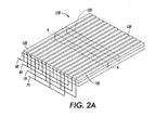
- FIGURE 2A is a schematic illustration of another preferred embodiment gel electrophoretic system in accordance with the present invention.
- FIGURE 2B is a wave diagram of a first set of electrical traveling waves utilized in the system of FIGURE 2A.
- FIGURE 2C is a wave diagram of a second set of electrical traveling waves utilized in the system of FIGURE 2A.
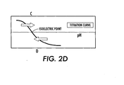
- FIGURE 2D is a representative titration curve illustrating an aspect of the present invention.
- the present invention provides an apparatus and a method to accelerate an IEF process or the IEF stage of a 2D process using such stage, by using electrostatic traveling waves having a particular polarity and directionality to selectively move or induce migration of both positive and negative proteins, biomolecules, or components thereof, in an electrophoretic gel system.
- the primary objective of using electrostatic traveling waves is the very rapid transport ofbiomolecules to be separated in a gel electrophoretic cell.
- This rapid transport is achieved by creating very high local electrical fields with low voltages using an electrode grid with a very fine pitch that is positioned in close proximity to the electrophoretic cell.
- Pitch is a characteristic of the grid dimensions and is the distance between electrode centers.
- the present invention provides several advantages over conventional gel setups including lower voltages (1V as compared to 200V for PAGE and 8,000 V for conventional IEF), and much higher transport velocities (up to 10 times or more). However, band broadening tends to occur due to the characteristic trait of this mode of transport.
- the methods of the present invention ensure that the biomolecules are loaded onto the analyzing cell, i.e. an immobilized pH gradient (IPG) strip, such that they are within reach of the electrical fields from the traveling wave grid.
- IPG immobilized pH gradient
- the biomolecules After several cycles of the traveling wave signal, the biomolecules synchronize their motion to move in step to the sweep frequency of the traveling wave signal. Once synchronized, the propagation velocity of the biomolecules in the operating regime of interest is approximately a linear function of the sweep frequency.
- FIGURE 1A is a schematic view of a preferred embodiment gel electrophoretic system 10 in accordance with the present invention.
- the system 10 includes an immobilized pH gradient (IPG) strip 20 and a multi-segmented traveling wave grid 30.
- the grid 30 includes a plurality of relatively fine and closely spaced parallel electrodes 32.
- the strip 20 is preferably oriented with respect to the grid 30 such that each electrode 32 extends in a direction that is generally perpendicular to the length dimension of the cell 20.
- the grid 30 is preferably a collection of individual grid segments that are in electrical communication to provide a single continuous grid. It will be appreciated, however, that in accordance with the present invention one or more grid segments may be selectively tailored or reconfigured with respect to the other grid segments.
- the preferred system 10 further includes a first traveling wave voltage controller 40, designated as controller A, and a second traveling wave voltage controller 50, designated as controller B. Each of the controllers 40 and 50 are in electrical communication with the grid 30 by corresponding busses 45 and 55, respectively.
- Disposed on the strip 20 is a first sample of biomolecules x and a second sample of biomolecules y.
- the biomolecules x have a positive native charge and the biomolecules y have a negative native charge.
- the first and second samples may be bands, patches, or remnants of biomolecules such as proteins that have already undergone separation or migration in the gel.
- biomolecules x migrate to a new position x'. That new position x' is closer to the location on the strip 20, and specifically within the gel medium therein, corresponding to the isoelectric point of biomolecule x. Ideally, that new position x' corresponds to the isoelectric point of biomolecule.
- biomolecules y having a negative native charge, are urged or directed towards side a of the strip 20 upon application of a positive electrical traveling wave directed towards side a of strip 20.
- FIGURE 1B illustrates a negative electrical traveling wave directed to side b of the strip 20 by controller 40.
- the controller 40 preferably generates a four (4) phase traveling wave in the form shown in FIGURE 1B, which travels toward side b of the strip 20.
- the negative traveling wave causes migration of biomolecules x having a positive charge also toward side b of the strip 20.
- the biomolecules x will travel in such direction to a location on the strip 20 corresponding to their isoelectric point, i.e. shown as x' in FIGURE 1A.
- FIGURE 1C illustrates a positive traveling wave directed to side a of the strip 20 by controller 50.
- the controller 50 preferably generates a four (4) phase traveling wave in the form shown in FIGURE 1C, which travels toward side a of the strip 20.
- the positive traveling wave causes migration of biomolecules y having a negative charge toward side a of the strip 20.
- the biomolecules y will travel in such direction to a location on the strip 20 corresponding to their isoelectric point, i.e. shown as y' in FIGURE 1A.
- the electrical signal generated by the controller is referred to as a traveling wave because the same change in voltage, i.e. the "valley” or negative voltage change in each phase of the wave diagram of FIGURE 1B or the “peak” or positive voltage change in each phase of the wave diagram of FIGURE 1C, "travels" from one phase to another as a function of time.
- the voltage changes i.e. the peaks or valleys
- a traveling wave of the desired type i.e. either a positive or negative wave, may be directed from any desired region of the grid, to any other desired region.
- the sets of traveling waves from controllers 40 and 50 are alternately applied to the grid 30.
- This alternating application of the sets of traveling waves causes progressive migration of biomolecules, i.e. biomolecules x and y, toward the corresponding isoelectric points of those biomolecules, or at least toward the center of the strip 20 and grid 30.
- This "focusing" effect reduces band broadening that otherwise typically occurs during IEF procedures.
- a preferred technique utilizing the system depicted in FIGURE 1A is to selectively alternate applications of the two controller signals to progressively migrate and focus the biomolecules.
- Controller 40 is arbitrarily selected to initially produce the desired voltage pattern, such as shown in FIGURE 1B, for an appropriate time interval equivalent to some integral number of cycles. Traveling waves of the pattern of FIGURE 1B are directed toward side b for a number of cycles. This number is generally the minimum number of cycles necessary for the biomolecules to synchronize their motion with the traveling wave signal.
- controller 50 is selected to produce or sweep traveling waves of the pattern of FIGURE 1C toward side a for the same number of cycles. At any given time, only one set of voltage pulses is applied to the grid 30. This method doubles the time needed but the rapid transport velocity of the biomolecules makes such method viable and attractive.
- FIGURE 2A illustrates another preferred embodiment gel electrophoretic system 110 in accordance with the present invention.
- the system 110 includes an IPG strip 120 disposed in intimate proximity to a traveling wave grid 130.
- the strip 120 has a first end a and a second end b, opposite from end a.
- the grid 130 includes a plurality of relatively fine and closely spaced parallel electrodes 132.
- the grid 130 is in electrical communication with a plurality of electrical busses, such as busses 60, 65, 70, and 75.
- the strip 120 is preferably oriented with respect to the grid 130 such that each electrode 132 extends in a direction that is generally perpendicular to the length dimension of the strip 120.
- FIGURE 2 B illustrates a negative electrical traveling wave directed to side b of the strip 120.
- the wave is preferably a four (4) phase traveling wave in the form shown in FIGURE 2B.
- FIGURE 2C illustrates a positive traveling wave directed to the other side of the strip 120, i.e. side a.
- FIGURE 2D is a representative titration curve for a biomolecule suitable for analysis by, for example, the system 110 shown in FIGURE 2A.
- application of the negative traveling wave of FIGURE 2B urges a biomolecule within the strip 120 to a location in the gel medium of the strip 120 at which the pH of the medium is the same, or substantially so, as the isoelectric point of the biomolecule.
- the biomolecule is proximate side a of the strip 120, it will be urged toward its isoelectric point in the direction of arrow c upon application of the negative traveling wave of FIGURE 2B.
- the biomolecule is proximate side b of the strip 120, it will be urged toward its isoelectric point in the direction of arrow D upon application of the positive traveling wave of FIGURE 2C.
- the preferred embodiment gel electrophoretic systems may utilize a single voltage controller or multiple voltage controllers. If multiple controllers are used, the controllers may be configured with the electrical grid such that each controller is dedicated to a segment, portion or region of the grid. Or, the controllers can be interfaced with the grid such that each controller is dedicated to particular electrodes, alternatingly arranged over a portion or the entirety of the grid. As described herein, it is preferred that the one or more controllers be configured to generate a wave signal having a polarity opposite from the native charge of the biomolecule to be migrated across a portion of the grid. However, the present invention includes a variety of controller configurations and wave forms for the traveling waves that result in biomolecule transport.
- the electrode grids of the present invention systems may be segmented such that a grid includes a plurality of grid segments. Each of the grid segments is physically separate from the other grid segments, however is in electrical communication with one or more controllers or with other segments. The various grid segments may be in electrical communication with other grid segments depending upon the overall system configuration.
- FIGURE 1A An example of a multi-segmented grid is shown in FIGURE 1A.
- FIGURE 2A illustrates a non-segmented grid.
- the electrode pitch preferably is in the range of from about 600 ⁇ m to about 10 ⁇ m, and more preferably from about 200 ⁇ m to about 40 ⁇ m.
- the spacing between opposing edges of adjacent electrodes is preferably from about 300 ⁇ m to about 7.5 ⁇ m and more preferably from about 100 ⁇ m to about 30 ⁇ m.
- the preferred voltage level applied to the grid and electrodes is from about 5 V to about 0.001 V, and more preferably about 2 V to about 0.10 V.
- the preferred frequency of the electrical signal depends upon the biomolecules to be migrated, however, frequencies in the range of from about 0.001 to about 10 Hz have been found useful, with preferred frequencies being from about 2 to about 0.020 Hz.
- Gel electrophoretic systems and cells, IPG strips, power sources, and controllers therefore may be obtained from one or more of the following suppliers: Proteome Systems Limited; Bio-Rad Laboratories; AMRESCO, Inc.; Invitrogen Corp.; Owl Separations Systems; R. Shadel Inc.; Stratagene; Zaxis, Inc.; and Amersham Biosciences.
- the present invention provides a new strategy to decrease the time required for an isoelectric focusing operation by utilizing a bi-directional dual traveling wave sweep. Furthermore, by adjusting and selecting a particular frequency for the traveling wave signals, individual focusing efforts may be directed for particular biomolecules. This methodology is particularly attractive for separation attempts ofbiomolecules having low or "shallow" slopes (with regard to their titration curve) near their isoelectric point.
Landscapes
- Health & Medical Sciences (AREA)
- Life Sciences & Earth Sciences (AREA)
- Molecular Biology (AREA)
- Chemical & Material Sciences (AREA)
- Chemical Kinetics & Catalysis (AREA)
- Electrochemistry (AREA)
- Physics & Mathematics (AREA)
- Analytical Chemistry (AREA)
- Biochemistry (AREA)
- General Health & Medical Sciences (AREA)
- General Physics & Mathematics (AREA)
- Immunology (AREA)
- Pathology (AREA)
- Engineering & Computer Science (AREA)
- Power Engineering (AREA)
- Peptides Or Proteins (AREA)
- Investigating Or Analysing Biological Materials (AREA)
Applications Claiming Priority (2)
| Application Number | Priority Date | Filing Date | Title |
|---|---|---|---|
| US10/460,724 US7150813B2 (en) | 2003-06-12 | 2003-06-12 | Isoelectric focusing (IEF) of proteins with sequential and oppositely directed traveling waves in gel electrophoresis |
| US460724 | 2003-06-12 |
Publications (2)
| Publication Number | Publication Date |
|---|---|
| EP1514875A1 true EP1514875A1 (de) | 2005-03-16 |
| EP1514875B1 EP1514875B1 (de) | 2014-01-15 |
Family
ID=33511072
Family Applications (1)
| Application Number | Title | Priority Date | Filing Date |
|---|---|---|---|
| EP04013740.8A Expired - Lifetime EP1514875B1 (de) | 2003-06-12 | 2004-06-11 | Isoelektrische Fokusierung von Proteinen mit sequentiellen und gegenläufigen Wanderwellen in Gelelektrophorese |
Country Status (3)
| Country | Link |
|---|---|
| US (1) | US7150813B2 (de) |
| EP (1) | EP1514875B1 (de) |
| JP (2) | JP4731131B2 (de) |
Families Citing this family (34)
| Publication number | Priority date | Publication date | Assignee | Title |
|---|---|---|---|---|
| US7811438B2 (en) * | 2004-12-08 | 2010-10-12 | Palo Alto Research Center Incorporated | Bio-enrichment device to enhance sample collection and detection |
| US20080210748A1 (en) | 2005-11-30 | 2008-09-04 | Searete Llc, A Limited Liability Corporation Of The State Of Delaware, | Systems and methods for receiving pathogen related information and responding |
| US20080241935A1 (en) | 2007-03-27 | 2008-10-02 | Searete Llc, A Limited Liability Corporation Of The State Of Delaware | Methods for pathogen detection |
| US7764005B2 (en) * | 2006-08-08 | 2010-07-27 | Palo Alto Research Center Incorporated | Traveling wave grids with agitated surface using piezoelectric effect and acoustic traveling waves |
| US7771580B2 (en) * | 2006-08-30 | 2010-08-10 | Palo Alto Research Center Incorporated | Particle extraction methods and systems for a particle concentrator |
| US8354076B2 (en) * | 2006-10-02 | 2013-01-15 | Palo Alto Research Center Incorporated | Fluid stirring mechanism |
| US7448287B2 (en) * | 2006-10-02 | 2008-11-11 | Palo Alto Research Center Incorporated | Pipette with agitation feature |
| US8617903B2 (en) | 2007-01-29 | 2013-12-31 | The Invention Science Fund I, Llc | Methods for allergen detection |
| US10001496B2 (en) | 2007-01-29 | 2018-06-19 | Gearbox, Llc | Systems for allergen detection |
| AU2008293381B2 (en) * | 2007-08-27 | 2012-07-19 | Technion Research & Development Foundation Ltd. | pH gradients controlled by electrolysis, and their use in isoelectric focusing |
| WO2009097240A1 (en) * | 2008-01-30 | 2009-08-06 | Dynamic Connections, Llc | Enhancing phoretic separation |
| US9475709B2 (en) | 2010-08-25 | 2016-10-25 | Lockheed Martin Corporation | Perforated graphene deionization or desalination |
| US9028663B2 (en) * | 2012-03-21 | 2015-05-12 | Lockheed Martin Corporation | Molecular separation device |
| US10376845B2 (en) | 2016-04-14 | 2019-08-13 | Lockheed Martin Corporation | Membranes with tunable selectivity |
| US9834809B2 (en) | 2014-02-28 | 2017-12-05 | Lockheed Martin Corporation | Syringe for obtaining nano-sized materials for selective assays and related methods of use |
| US9744617B2 (en) | 2014-01-31 | 2017-08-29 | Lockheed Martin Corporation | Methods for perforating multi-layer graphene through ion bombardment |
| US9844757B2 (en) | 2014-03-12 | 2017-12-19 | Lockheed Martin Corporation | Separation membranes formed from perforated graphene and methods for use thereof |
| US9610546B2 (en) | 2014-03-12 | 2017-04-04 | Lockheed Martin Corporation | Separation membranes formed from perforated graphene and methods for use thereof |
| US10653824B2 (en) | 2012-05-25 | 2020-05-19 | Lockheed Martin Corporation | Two-dimensional materials and uses thereof |
| WO2014028173A1 (en) * | 2012-08-15 | 2014-02-20 | Array Bridge Inc. | Methods for protein purification and analysis |
| TW201504140A (zh) | 2013-03-12 | 2015-02-01 | Lockheed Corp | 形成具有均勻孔尺寸之多孔石墨烯之方法 |
| US9572918B2 (en) | 2013-06-21 | 2017-02-21 | Lockheed Martin Corporation | Graphene-based filter for isolating a substance from blood |
| CN105940479A (zh) | 2014-01-31 | 2016-09-14 | 洛克希德马丁公司 | 使用宽离子场穿孔二维材料 |
| CN106029596A (zh) | 2014-01-31 | 2016-10-12 | 洛克希德马丁公司 | 采用多孔非牺牲性支撑层的二维材料形成复合结构的方法 |
| JP2017534311A (ja) | 2014-09-02 | 2017-11-24 | ロッキード・マーチン・コーポレーション | 二次元膜材料をベースとする血液透析膜および血液濾過膜、ならびにそれを用いた方法 |
| JP2018528144A (ja) | 2015-08-05 | 2018-09-27 | ロッキード・マーチン・コーポレーション | グラフェン系材料の穿孔可能なシート |
| WO2017023377A1 (en) | 2015-08-06 | 2017-02-09 | Lockheed Martin Corporation | Nanoparticle modification and perforation of graphene |
| EP3442697A4 (de) | 2016-04-14 | 2020-03-18 | Lockheed Martin Corporation | Selektive grenzflächenminderung von graphendefekten |
| EP3442739A4 (de) | 2016-04-14 | 2020-03-04 | Lockheed Martin Corporation | Verfahren zur behandlung von graphenfolien für grossflächigen transfer mittels free-float-verfahren |
| WO2017180134A1 (en) | 2016-04-14 | 2017-10-19 | Lockheed Martin Corporation | Methods for in vivo and in vitro use of graphene and other two-dimensional materials |
| KR20180133430A (ko) | 2016-04-14 | 2018-12-14 | 록히드 마틴 코포레이션 | 결함 형성 또는 힐링의 인 시츄 모니터링 및 제어를 위한 방법 |
| EP3442786A4 (de) | 2016-04-14 | 2020-03-18 | Lockheed Martin Corporation | Zweidimensionale membranstrukturen mit strömungskanälen |
| CN110777747B (zh) * | 2019-10-29 | 2021-06-15 | 南京川源水务有限公司 | 一种河道拦污系统 |
| CN117199152B (zh) * | 2023-09-11 | 2024-06-04 | 淮安捷泰新能源科技有限公司 | 一种太阳能电池及其制备方法 |
Citations (2)
| Publication number | Priority date | Publication date | Assignee | Title |
|---|---|---|---|---|
| US4900414A (en) | 1988-08-19 | 1990-02-13 | Drug Delivery Systems Inc. | Commercial separation system and method using electrokinetic techniques |
| US6296752B1 (en) * | 1998-06-05 | 2001-10-02 | Sarnoff Corporation | Apparatus for separating molecules |
Family Cites Families (23)
| Publication number | Priority date | Publication date | Assignee | Title |
|---|---|---|---|---|
| US4473452A (en) * | 1982-11-18 | 1984-09-25 | The Trustees Of Columbia University In The City Of New York | Electrophoresis using alternating transverse electric fields |
| US4647179A (en) * | 1984-05-29 | 1987-03-03 | Xerox Corporation | Development apparatus |
| US4737251A (en) * | 1985-09-27 | 1988-04-12 | Washington University | Field-inversion gel electrophoresis |
| JPH01100448A (ja) * | 1987-10-13 | 1989-04-18 | Shimadzu Corp | 等電点電気泳動用ゲル媒体 |
| US5126022A (en) * | 1990-02-28 | 1992-06-30 | Soane Tecnologies, Inc. | Method and device for moving molecules by the application of a plurality of electrical fields |
| US5208458A (en) * | 1991-11-05 | 1993-05-04 | Georgia Tech Research Corporation | Interface device to couple gel electrophoresis with mass spectrometry using sample disruption |
| GB9301122D0 (en) * | 1993-01-21 | 1993-03-10 | Scient Generics Ltd | Method of analysis/separation |
| US5534121A (en) | 1994-05-16 | 1996-07-09 | The United States Of America As Represented By The Department Of Health And Human Services | Preparative two dimensional gel electrophoresis system |
| US5532121A (en) * | 1995-03-24 | 1996-07-02 | Minnesota Mining And Manufacturing Company | Mottle reducing agent for photothermographic and thermographic elements |
| US5938904A (en) * | 1996-03-27 | 1999-08-17 | Curagen Corporation | Separation of charged particles by a spatially and temporally varying electric field |
| US5837116A (en) * | 1996-07-12 | 1998-11-17 | California Institute Of Technology | Two dimensional electrophoresis apparatus |
| US6358752B1 (en) * | 1996-09-27 | 2002-03-19 | Cornell Research Foundation, Inc. | Liposome-enhanced test device and method |
| US6013165A (en) * | 1998-05-22 | 2000-01-11 | Lynx Therapeutics, Inc. | Electrophoresis apparatus and method |
| WO2000013007A1 (en) * | 1998-08-31 | 2000-03-09 | C.B.S. Scientific Co., Inc. | Two dimensional gel electrophoresis system |
| AU4773400A (en) | 1999-05-28 | 2000-12-18 | Leisamon (Israel), Ltd. | Methods and apparatus for nonlinear mobility electrophoresis separation |
| GB9916848D0 (en) * | 1999-07-20 | 1999-09-22 | Univ Wales Bangor | Travelling wave dielectrophoretic apparatus and method |
| GB9916850D0 (en) * | 1999-07-20 | 1999-09-22 | Univ Wales Bangor | Dielectrophoretic apparatus & method |
| US6272296B1 (en) * | 1999-12-10 | 2001-08-07 | Xerox Corporation | Method and apparatus using traveling wave potential waveforms for separation of opposite sign charge particles |
| CN1325909C (zh) * | 2000-09-27 | 2007-07-11 | 清华大学 | 用于微粒操纵与微粒导向的装置及其使用方法 |
| CN100495030C (zh) * | 2000-09-30 | 2009-06-03 | 清华大学 | 多力操纵装置及其应用 |
| WO2002036464A1 (en) * | 2000-11-03 | 2002-05-10 | Technology Innovations, Llc | Powder conveying and dispensing method and apparatus using traveling wave transport |
| EP1360479A4 (de) * | 2001-02-15 | 2005-03-23 | Caliper Life Sciences Inc | Verfahren und systeme zur verbesserten ablieferung elektrischer ströme an fluidische systeme |
| US6655649B2 (en) * | 2002-03-11 | 2003-12-02 | Bio-Rad Laboratories, Inc. | Assembly for casting and use of an isoelectric focusing strip |
-
2003
- 2003-06-12 US US10/460,724 patent/US7150813B2/en not_active Expired - Lifetime
-
2004
- 2004-06-11 JP JP2004174780A patent/JP4731131B2/ja not_active Expired - Fee Related
- 2004-06-11 EP EP04013740.8A patent/EP1514875B1/de not_active Expired - Lifetime
-
2010
- 2010-07-27 JP JP2010168508A patent/JP4892089B2/ja not_active Expired - Fee Related
Patent Citations (2)
| Publication number | Priority date | Publication date | Assignee | Title |
|---|---|---|---|---|
| US4900414A (en) | 1988-08-19 | 1990-02-13 | Drug Delivery Systems Inc. | Commercial separation system and method using electrokinetic techniques |
| US6296752B1 (en) * | 1998-06-05 | 2001-10-02 | Sarnoff Corporation | Apparatus for separating molecules |
Non-Patent Citations (3)
| Title |
|---|
| BJELLQVIST B ET AL: "ISOELECTRIC FOCUSING IN IMMOBILIZED PH GRADIENTS: PRINCIPLE, METHODOLOGY AND SOME APPLICATIONS", JOURNAL OF BIOCHEMICAL AND BIOPHYSICAL METHODS, AMSTERDAM, NL, vol. 6, 1982, pages 317 - 339, XP008007126, ISSN: 0165-022X * |
| DUNPHY ET AL.: "Rapid Separation and Manipulation of DNA by a Ratcheting Electrophoresis Microchip (REM", PROCEEDINGS OF IMECE2002, 17 November 2002 (2002-11-17) |
| HAGEDORN R ET AL: "TRAVELING-WAVE DIELECTROPHORESIS OF MICROPARTICLES", ELECTROPHORESIS, WEINHEIM, DE, vol. 13, no. 1/2, January 1992 (1992-01-01), pages 49 - 54, XP000430628, ISSN: 0173-0835 * |
Also Published As
| Publication number | Publication date |
|---|---|
| JP2010237227A (ja) | 2010-10-21 |
| US20040251136A1 (en) | 2004-12-16 |
| EP1514875B1 (de) | 2014-01-15 |
| JP4892089B2 (ja) | 2012-03-07 |
| JP4731131B2 (ja) | 2011-07-20 |
| US7150813B2 (en) | 2006-12-19 |
| JP2005003686A (ja) | 2005-01-06 |
Similar Documents
| Publication | Publication Date | Title |
|---|---|---|
| US7150813B2 (en) | Isoelectric focusing (IEF) of proteins with sequential and oppositely directed traveling waves in gel electrophoresis | |
| EP1486782B1 (de) | Verteiltes multi-segmentiertes rekonfigurierbares Wanderwellengitter zur gelelektrophoretischen Separation von Proteinen | |
| EP1486781B1 (de) | Wanderwellen-Algorithmen zur Fokusierung und Konzentration von Proteinen in Gelektrophorese | |
| EP1410029B1 (de) | Puffer-arrays zum nachweis von biomolekülen anhand ihres isoelektrischen punktes | |
| JP3103031B2 (ja) | 電界の印加により分子を移動させる方法および装置 | |
| US20010023825A1 (en) | Methods and apparatus for nonlinear mobility electrophoresis separation | |
| US4900414A (en) | Commercial separation system and method using electrokinetic techniques | |
| US7126134B2 (en) | Sample manipulator | |
| US7309410B2 (en) | Traveling wave grids and algorithms for biomolecule separation, transport and focusing | |
| US20080272002A1 (en) | System and Method for Proteomics | |
| EP1211510A1 (de) | Verfahren und Vorrichtung zur nichtlinear beweglichen, elektrophoretischen Trennung | |
| US20050061714A1 (en) | Sorting charged particles | |
| EP1341806A1 (de) | Verfahren und vorrichtung zur abtrennung von biomolekülen | |
| Shinde Dipa et al. | REVIEW ON: ELECTROPHORESIS: METHOD FOR PROTEIN SEPARATION. | |
| Garfin | Electrophoretic methods | |
| Rolchigo et al. | Analytical and preparative electrophoresis in a nonuniform electric field | |
| Lee et al. | Analytical and preparative capillary zone electrophoresis of opioid peptides | |
| US20090188800A1 (en) | Enhancing phoretic separation | |
| Ohara et al. | Transport of biomolecules in the ratcheting electrophoresis microchip (REM) | |
| Kalidas et al. | Capillary Electrophoresis | |
| GB2430636A (en) | A separation system | |
| van de Goor | Capillary electrophoresis of proteins | |
| Ohara et al. | Ratcheting electrophoresis microchip (REM) for programmable transport and separation of macromolecules | |
| Kaur et al. | Electrophoresis: A Conceptual Understanding |
Legal Events
| Date | Code | Title | Description |
|---|---|---|---|
| PUAI | Public reference made under article 153(3) epc to a published international application that has entered the european phase |
Free format text: ORIGINAL CODE: 0009012 |
|
| AK | Designated contracting states |
Kind code of ref document: A1 Designated state(s): AT BE BG CH CY CZ DE DK EE ES FI FR GB GR HU IE IT LI LU MC NL PL PT RO SE SI SK TR |
|
| AX | Request for extension of the european patent |
Extension state: AL HR LT LV MK |
|
| 17P | Request for examination filed |
Effective date: 20050916 |
|
| AKX | Designation fees paid |
Designated state(s): DE FR GB |
|
| 17Q | First examination report despatched |
Effective date: 20080819 |
|
| GRAP | Despatch of communication of intention to grant a patent |
Free format text: ORIGINAL CODE: EPIDOSNIGR1 |
|
| INTG | Intention to grant announced |
Effective date: 20130801 |
|
| GRAS | Grant fee paid |
Free format text: ORIGINAL CODE: EPIDOSNIGR3 |
|
| GRAA | (expected) grant |
Free format text: ORIGINAL CODE: 0009210 |
|
| AK | Designated contracting states |
Kind code of ref document: B1 Designated state(s): DE FR GB |
|
| REG | Reference to a national code |
Ref country code: GB Ref legal event code: FG4D |
|
| REG | Reference to a national code |
Ref country code: DE Ref legal event code: R096 Ref document number: 602004044240 Country of ref document: DE Effective date: 20140220 |
|
| REG | Reference to a national code |
Ref country code: DE Ref legal event code: R097 Ref document number: 602004044240 Country of ref document: DE |
|
| PLBE | No opposition filed within time limit |
Free format text: ORIGINAL CODE: 0009261 |
|
| STAA | Information on the status of an ep patent application or granted ep patent |
Free format text: STATUS: NO OPPOSITION FILED WITHIN TIME LIMIT |
|
| 26N | No opposition filed |
Effective date: 20141016 |
|
| REG | Reference to a national code |
Ref country code: DE Ref legal event code: R097 Ref document number: 602004044240 Country of ref document: DE Effective date: 20141016 |
|
| REG | Reference to a national code |
Ref country code: FR Ref legal event code: PLFP Year of fee payment: 13 |
|
| REG | Reference to a national code |
Ref country code: FR Ref legal event code: PLFP Year of fee payment: 14 |
|
| REG | Reference to a national code |
Ref country code: FR Ref legal event code: PLFP Year of fee payment: 15 |
|
| PGFP | Annual fee paid to national office [announced via postgrant information from national office to epo] |
Ref country code: DE Payment date: 20190521 Year of fee payment: 16 |
|
| PGFP | Annual fee paid to national office [announced via postgrant information from national office to epo] |
Ref country code: FR Payment date: 20190522 Year of fee payment: 16 |
|
| PGFP | Annual fee paid to national office [announced via postgrant information from national office to epo] |
Ref country code: GB Payment date: 20190522 Year of fee payment: 16 |
|
| REG | Reference to a national code |
Ref country code: DE Ref legal event code: R119 Ref document number: 602004044240 Country of ref document: DE |
|
| GBPC | Gb: european patent ceased through non-payment of renewal fee |
Effective date: 20200611 |
|
| PG25 | Lapsed in a contracting state [announced via postgrant information from national office to epo] |
Ref country code: FR Free format text: LAPSE BECAUSE OF NON-PAYMENT OF DUE FEES Effective date: 20200630 Ref country code: GB Free format text: LAPSE BECAUSE OF NON-PAYMENT OF DUE FEES Effective date: 20200611 |
|
| PG25 | Lapsed in a contracting state [announced via postgrant information from national office to epo] |
Ref country code: DE Free format text: LAPSE BECAUSE OF NON-PAYMENT OF DUE FEES Effective date: 20210101 |