EP1514767A1 - Kraftfahrzeugstruktur - Google Patents
Kraftfahrzeugstruktur Download PDFInfo
- Publication number
- EP1514767A1 EP1514767A1 EP04300582A EP04300582A EP1514767A1 EP 1514767 A1 EP1514767 A1 EP 1514767A1 EP 04300582 A EP04300582 A EP 04300582A EP 04300582 A EP04300582 A EP 04300582A EP 1514767 A1 EP1514767 A1 EP 1514767A1
- Authority
- EP
- European Patent Office
- Prior art keywords
- frame
- structure according
- framework
- floor
- interposed
- Prior art date
- Legal status (The legal status is an assumption and is not a legal conclusion. Google has not performed a legal analysis and makes no representation as to the accuracy of the status listed.)
- Withdrawn
Links
Images


Classifications
-
- B—PERFORMING OPERATIONS; TRANSPORTING
- B62—LAND VEHICLES FOR TRAVELLING OTHERWISE THAN ON RAILS
- B62D—MOTOR VEHICLES; TRAILERS
- B62D25/00—Superstructure or monocoque structure sub-units; Parts or details thereof not otherwise provided for
- B62D25/20—Floors or bottom sub-units
-
- B—PERFORMING OPERATIONS; TRANSPORTING
- B62—LAND VEHICLES FOR TRAVELLING OTHERWISE THAN ON RAILS
- B62D—MOTOR VEHICLES; TRAILERS
- B62D25/00—Superstructure or monocoque structure sub-units; Parts or details thereof not otherwise provided for
- B62D25/06—Fixed roofs
-
- B—PERFORMING OPERATIONS; TRANSPORTING
- B62—LAND VEHICLES FOR TRAVELLING OTHERWISE THAN ON RAILS
- B62D—MOTOR VEHICLES; TRAILERS
- B62D27/00—Connections between superstructure or understructure sub-units
- B62D27/04—Connections between superstructure or understructure sub-units resilient
Definitions
- the invention relates to a vehicle structure automobile.
- the invention relates more particularly to a structure of a motor vehicle having a frame on which are rigidly fixed panels such as floors and pavilions.
- the sound comfort of a vehicle depends on the noise level in the cockpit. Part of the noises in the cockpit of a vehicle is generated by the vibration of the panels attached to the frame of the vehicle, such as floors or pavilions.
- the vibration modes of a framework are the overvoltages or peaks of intensity that appear in a structure that deforms under the influence of vibrations. These vibrations are transmitted to panels that react as the skin of a drum.
- the noise reduction generated by the panels is obtained either by an acoustic insulation solution or by decreasing the vibratory response of the panels.
- the vibratory response of the panels must be greater than 200Hz, so that they are not coupled with the frequencies of resonance of the cavities of the frame of the vehicle.
- An object of the present invention is to mitigate all or part of the disadvantages of the prior art noted above.
- the vehicle structure according to the invention is essentially characterized by that one or less of the panels is attached to the framework by fastening means arranged at the level of nodal lines or immobile points during resonant vibration modes of the frame, and in that damping means are interposed between the panel and the framework and / or at the the framework, so as to ensure a vibratory decoupling between the frame and the panel.
- the frame 1 of a motor vehicle represented in FIG. 1 comprises, in its upper part, beams 11 or roof arches and, on the other hand, transverse beams such as crosspieces 12, 13.
- the roof arches 11 and crosspieces 12, 13 delimit a parallelepiped opening intended to be closed by a panel attached to the frame 1 forming a flag.
- the sleepers 12 are fixed to the frame 1 so decoupled. That is, the sleepers 12 are fixed on the frame 1 (roof arches 11) by fastening means arranged at the level of nodal lines or immobile points of the framework during resonant vibration modes of the backbone. More specifically, the cross members 12 are fixed on the arches of flags 11 at the nodes, that is to say calm spots that do not suffer or little displacement during the vibration of the framework 1. The fixation can be achieved by screwing and / or riveting and / or welding.
- nodes or nodal lines are classically determined by calculation by means of software using the finite element technique of mesh of the surface or volume considered.
- other techniques exist to determine these calm points, by example the known technique of Doppler interferometry.
- a damping element 6 is interposed between each end of the crosspiece 12 and the bow of flag 11 corresponding. That is, the crossbar 12 is "isolated" of the frame 1 from a vibratory point of view.
- crosses 12 are solicited mainly in tension / compression and thus dampen vibrations they suffer.
- the damping means 7 is interposed between the flag 3 and the 12.
- the damping means consists of preferably one or more pads 7 made of elastomeric material such as, for example, those marketed under the trade marks SORBOTHANE® or NAVCOM®.
- the means damper has a hardness between 70 and 80 shores about.
- the pads 7 may have parallelepipedal shapes, cylindrical or hemispherical. Preferably, the one or more pads 7 have dimensions of between 30 and 100 mm approximately.
- the pads 7 are preferably placed at the level of bellows deformation of the panel, that is to say at the likely to experience the greatest vibrational displacements (these are determined in the same way as the lines nodal)
- the assembly consisting of the flag 3 and sleepers transverse 12 is decoupled from the rest of the framework 1 (such a floating ceiling). It is found according to the invention a decrease significant vibration of the pavilion responsible for acoustic humming.
- FIG. 3 differs from that previously described in that the sleepers 12 are fixed at roof arches 11 in a conventional manner (ie without decoupling) by means of, for example screws, rivets 26 or point Welding.
- the flag 3 is fastened to the sleepers 12 and / or on the roof arches 11 by fixing means 4 arranged at the level of nodal lines of the frame 1.
- a seal may be provided at the level of the the periphery of pavilion 3, to ensure the seal between the interior and exterior of the cabin.
- a damping means 7 is interposed between the flag 3 and the sleepers 12.
- the flag 3 is decoupled from the rest of the frame 1 (including sleepers), such as a floating ceiling, which reduces significantly the acoustic emission of flag 3.
- the sleepers are replaced or replaced by a crossbar system consisting of two beams 14 crossed and whose ends are attached to arches 11 of flag.
- a damping element 6 can be interposed between each end of a beam 14 of brace and the corresponding roof bow 11, so as to "isolate” from a vibration point of view the cross 14 of the frame 1.
- One or more damping pads 7 are arranged on the cross 14 so as to be interposed between the flag and the cross 14.
- the studs concerned have stiffness and viscoelasticity different, adapted to the frequencies to be damped.
- the arrangement according to the invention also gives the flag good strength and strength without requiring parts and in particular to reduce the number of welds compared to systems known.
- Such an arrangement is furthermore more compatible with a passage of the framework in cataphoresis.
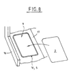
- the structure of vehicle has a floor panel 2 attached to the level of its periphery on the border 10 of an opening 9 formed in the lower part of the framework 1.
- the floor 2 is the one located partly before the vehicle.
- the opening 9 is located for example between a spar 16 and a tunnel 17 of the lower part of the backbone.
- the floor consists for example of one or more stacked metal plates or a sandwich stack stamped metal plates and sheets of material plastic.
- a stiffening rib 8 can be provided on around the floor 2.
- the floor 2 is fixed on the frame 1 by fixing means 4 arranged at the level of lines nodal or immobile points during vibration modes resonant of the framework 1.
- the nodal lines of the first resonance mode of the floor are located on the around the floor 2.
- the bellies are located in the central part of the floor 2.
- the fastening means may comprise screws, rivets, welding points or any other equivalent system.
- damping means 5 are interposed between the floor 2 and the frame 1. These damping means can be made of the same materials as those mentioned above.
- the means dampers are arranged at the level of the bellies, so substantially in the center of the floor with respect to the first mode of vibration.
- the invention provides a vibratory decoupling between the frame 1 and the floor 2.
- the means 5 dampers are preferably constituted by a cord 5 forming a loop closed at the edge 10 of the opening 9.
- This cord 5 is deposited for example, by a nozzle during manufacture of the frame.
- the edge 10 of the opening 9 can have the shape of a concave channel or trowel intended for accommodate the cord 5 shock absorber.
- the arrangement of such a floor according to the present invention good solidity and held in time and does not require additional seals as in the devices of the prior art.
- the invention allows to guarantee a good acoustic comfort despite a fixation of panels by simple screws, rivets or welds.
- the fixing of the panels according to the invention at the level of nodal lines with addition of simple damping means allows to get rid of art fixing devices prior art which include complex filtering means and expensive.
- the arrangement of the floor 2 according to the invention thus allows to seal between the floor 2 and the frame 1 of the "medallion" type as shown in FIG. configuration allows to get rid of the systems sealant seals made at the junction of each pair of adjacent sheets, without any logic geometric.
- the invention applies in particular advantageously vehicle structures whose frame has a stiffness in twist less than 1 billion, and preferably less than 0.8 bn.
- the vibration decoupling of one or more panels in relation to the frame has very serious consequences limited to the impact resistance of the structure (respect for conditions of approval in case of impact with intrusion).
- the invention can of course be applied to other examples of vehicle structure panels.
Landscapes
- Engineering & Computer Science (AREA)
- Chemical & Material Sciences (AREA)
- Combustion & Propulsion (AREA)
- Transportation (AREA)
- Mechanical Engineering (AREA)
- Body Structure For Vehicles (AREA)
Applications Claiming Priority (2)
| Application Number | Priority Date | Filing Date | Title |
|---|---|---|---|
| FR0310620 | 2003-09-09 | ||
| FR0310620A FR2859442B1 (fr) | 2003-09-09 | 2003-09-09 | Structure de vehicule automobile |
Publications (1)
| Publication Number | Publication Date |
|---|---|
| EP1514767A1 true EP1514767A1 (de) | 2005-03-16 |
Family
ID=34130775
Family Applications (1)
| Application Number | Title | Priority Date | Filing Date |
|---|---|---|---|
| EP04300582A Withdrawn EP1514767A1 (de) | 2003-09-09 | 2004-09-08 | Kraftfahrzeugstruktur |
Country Status (2)
| Country | Link |
|---|---|
| EP (1) | EP1514767A1 (de) |
| FR (1) | FR2859442B1 (de) |
Cited By (4)
| Publication number | Priority date | Publication date | Assignee | Title |
|---|---|---|---|---|
| FR2897829A1 (fr) * | 2006-02-24 | 2007-08-31 | Peugeot Citroen Automobiles Sa | Structure de vehicule automobile anti-vibrations. |
| FR2901337A1 (fr) * | 2006-05-22 | 2007-11-23 | Peugeot Citroen Automobiles Sa | Tirant amortissant pour vehicule automobile et vehicule automobile equipe d'un tirant amortissant. |
| CN105966469A (zh) * | 2016-06-14 | 2016-09-28 | 北京新能源汽车股份有限公司 | 车辆的前地板与前横梁的连接结构及车辆 |
| CN113525517A (zh) * | 2021-06-21 | 2021-10-22 | 重庆尊航机械制造有限公司 | 减振型车架 |
Families Citing this family (2)
| Publication number | Priority date | Publication date | Assignee | Title |
|---|---|---|---|---|
| FR2890031B1 (fr) * | 2005-08-26 | 2009-04-03 | Inoplast Sa | Structure de toit pour un vehicule, vehicule muni de cette structure et procede d'assemblage de cette structure a une caisse de vehicule |
| FR2890368B1 (fr) * | 2005-09-02 | 2007-11-30 | Plastic Omnium Cie | Caisse en blanc de vehicule automobile |
Citations (6)
| Publication number | Priority date | Publication date | Assignee | Title |
|---|---|---|---|---|
| US3149856A (en) * | 1959-08-17 | 1964-09-22 | Smith Corp A O | Motor vehicle having increased ground clearance level floor space |
| DE2344062A1 (de) * | 1972-09-02 | 1974-03-07 | Perkins Engines Ltd | Verfahren und anordnung zum schwingungstechnischen isolieren eines bestandteils einer konstruktion gegenueber einem anderen bestandteil |
| US4352520A (en) * | 1977-12-03 | 1982-10-05 | Maschinenfabrik Augsburg-Nurnberg Aktiengesellschaft | Composite of a vehicle frame and body parts |
| DE4401041A1 (de) * | 1993-01-29 | 1994-08-04 | Volkswagen Ag | Schwingungsgefährdetes plattenförmiges Bauteil, insbesondere Kraftfahrzeug-Aufbauteil |
| US5339745A (en) * | 1992-06-24 | 1994-08-23 | Alusuisse-Lonza Services Ltd. | Sound proofing and vibration dampening elastic connecting element |
| JP2000064354A (ja) * | 1998-08-20 | 2000-02-29 | Hitachi Constr Mach Co Ltd | 建設機械 |
-
2003
- 2003-09-09 FR FR0310620A patent/FR2859442B1/fr not_active Expired - Fee Related
-
2004
- 2004-09-08 EP EP04300582A patent/EP1514767A1/de not_active Withdrawn
Patent Citations (6)
| Publication number | Priority date | Publication date | Assignee | Title |
|---|---|---|---|---|
| US3149856A (en) * | 1959-08-17 | 1964-09-22 | Smith Corp A O | Motor vehicle having increased ground clearance level floor space |
| DE2344062A1 (de) * | 1972-09-02 | 1974-03-07 | Perkins Engines Ltd | Verfahren und anordnung zum schwingungstechnischen isolieren eines bestandteils einer konstruktion gegenueber einem anderen bestandteil |
| US4352520A (en) * | 1977-12-03 | 1982-10-05 | Maschinenfabrik Augsburg-Nurnberg Aktiengesellschaft | Composite of a vehicle frame and body parts |
| US5339745A (en) * | 1992-06-24 | 1994-08-23 | Alusuisse-Lonza Services Ltd. | Sound proofing and vibration dampening elastic connecting element |
| DE4401041A1 (de) * | 1993-01-29 | 1994-08-04 | Volkswagen Ag | Schwingungsgefährdetes plattenförmiges Bauteil, insbesondere Kraftfahrzeug-Aufbauteil |
| JP2000064354A (ja) * | 1998-08-20 | 2000-02-29 | Hitachi Constr Mach Co Ltd | 建設機械 |
Non-Patent Citations (1)
| Title |
|---|
| PATENT ABSTRACTS OF JAPAN vol. 2000, no. 05 14 September 2000 (2000-09-14) * |
Cited By (4)
| Publication number | Priority date | Publication date | Assignee | Title |
|---|---|---|---|---|
| FR2897829A1 (fr) * | 2006-02-24 | 2007-08-31 | Peugeot Citroen Automobiles Sa | Structure de vehicule automobile anti-vibrations. |
| FR2901337A1 (fr) * | 2006-05-22 | 2007-11-23 | Peugeot Citroen Automobiles Sa | Tirant amortissant pour vehicule automobile et vehicule automobile equipe d'un tirant amortissant. |
| CN105966469A (zh) * | 2016-06-14 | 2016-09-28 | 北京新能源汽车股份有限公司 | 车辆的前地板与前横梁的连接结构及车辆 |
| CN113525517A (zh) * | 2021-06-21 | 2021-10-22 | 重庆尊航机械制造有限公司 | 减振型车架 |
Also Published As
| Publication number | Publication date |
|---|---|
| FR2859442B1 (fr) | 2005-10-21 |
| FR2859442A1 (fr) | 2005-03-11 |
Similar Documents
| Publication | Publication Date | Title |
|---|---|---|
| JP5698340B2 (ja) | 車体後部構造 | |
| EP2560839A1 (de) | Schutzplatte zur anbringung an einem teil der karosserie eines motorfahrzeugs und mit einer derartigen schutztafel ausgestattetes motorfahrzeug | |
| EP1514767A1 (de) | Kraftfahrzeugstruktur | |
| FR2998524A1 (fr) | Ensemble de pare-chocs pour vehicule automobile a deux demi-coques | |
| FR3055880B1 (fr) | Structure superieure de carrosserie de vehicule | |
| WO2008090274A1 (fr) | Dispositif de liaison de deux éléments de structure de véhicule automobile | |
| EP2282076B1 (de) | Schwingungsdämpfervorrichtung für ein Fahrzeug, und eine solche Vorrichtung umfassendes Fahrzeug | |
| FR3071812A1 (fr) | Structure inferieure de vehicule | |
| FR3051172A1 (fr) | Longeron lateral de toit pour vehicule | |
| EP4351953A1 (de) | Stossdämpferelement für ein kraftfahrzeug | |
| EP3256348A1 (de) | Zentraler träger für hintere stossstange | |
| JP5618329B2 (ja) | 車両の車体上部構造 | |
| FR3065432A1 (fr) | Structure de toit | |
| JP7006641B2 (ja) | 車体上部構造 | |
| FR3065431A1 (fr) | Structure de toit | |
| JP6241469B2 (ja) | 車両の車体構造 | |
| FR3026694A1 (fr) | Ensemble de pare-chocs pour vehicule automobile comprenant un absorbeur en materiau composite | |
| FR2941670A1 (fr) | Structure de vehicule automobile comportant une peau ex-terieure et des elements de renfort et vehicule equipee d'une telle structure. | |
| EP4222008A1 (de) | Fahrzeug mit einem schalldämmelement zwischen dem boden und einer elektrischen batterie | |
| JP6917413B2 (ja) | フロントピラー構造 | |
| JP2009154744A (ja) | 自動車用ボディ構造体 | |
| KR101347524B1 (ko) | 후석 소음 저감을 위한 리어 크로스 멤버 | |
| JP4328947B2 (ja) | リヤサスペンション周りの車体構造 | |
| FR2897586A1 (fr) | Plancher en matiere plastique et en elastomere de vehicule automobile | |
| JP7021655B2 (ja) | 車体上部構造 |
Legal Events
| Date | Code | Title | Description |
|---|---|---|---|
| PUAI | Public reference made under article 153(3) epc to a published international application that has entered the european phase |
Free format text: ORIGINAL CODE: 0009012 |
|
| AK | Designated contracting states |
Kind code of ref document: A1 Designated state(s): AT BE BG CH CY CZ DE DK EE ES FI FR GB GR HU IE IT LI LU MC NL PL PT RO SE SI SK TR |
|
| AX | Request for extension of the european patent |
Extension state: AL HR LT LV MK |
|
| 17P | Request for examination filed |
Effective date: 20050425 |
|
| AKX | Designation fees paid |
Designated state(s): AT BE BG CH CY CZ DE DK EE ES FI FR GB GR HU IE IT LI LU MC NL PL PT RO SE SI SK TR |
|
| GRAP | Despatch of communication of intention to grant a patent |
Free format text: ORIGINAL CODE: EPIDOSNIGR1 |
|
| STAA | Information on the status of an ep patent application or granted ep patent |
Free format text: STATUS: THE APPLICATION IS DEEMED TO BE WITHDRAWN |
|
| 18D | Application deemed to be withdrawn |
Effective date: 20081007 |