EP1514740B1 - Dispositif d'arceau de sécurité pour véhicules avec un arceau déployable - Google Patents
Dispositif d'arceau de sécurité pour véhicules avec un arceau déployable Download PDFInfo
- Publication number
- EP1514740B1 EP1514740B1 EP04021072A EP04021072A EP1514740B1 EP 1514740 B1 EP1514740 B1 EP 1514740B1 EP 04021072 A EP04021072 A EP 04021072A EP 04021072 A EP04021072 A EP 04021072A EP 1514740 B1 EP1514740 B1 EP 1514740B1
- Authority
- EP
- European Patent Office
- Prior art keywords
- roll
- release
- actuator
- protection system
- pin
- Prior art date
- Legal status (The legal status is an assumption and is not a legal conclusion. Google has not performed a legal analysis and makes no representation as to the accuracy of the status listed.)
- Expired - Lifetime
Links
- 230000006835 compression Effects 0.000 claims description 12
- 238000007906 compression Methods 0.000 claims description 12
- 230000001681 protective effect Effects 0.000 claims description 6
- 238000010276 construction Methods 0.000 claims description 4
- 230000004323 axial length Effects 0.000 claims description 2
- 230000004913 activation Effects 0.000 claims 1
- 230000005283 ground state Effects 0.000 description 3
- 230000003213 activating effect Effects 0.000 description 2
- WQGWDDDVZFFDIG-UHFFFAOYSA-N pyrogallol Chemical compound OC1=CC=CC(O)=C1O WQGWDDDVZFFDIG-UHFFFAOYSA-N 0.000 description 2
- 230000000717 retained effect Effects 0.000 description 2
- 230000001960 triggered effect Effects 0.000 description 2
- 238000013270 controlled release Methods 0.000 description 1
- 230000006735 deficit Effects 0.000 description 1
- 230000001419 dependent effect Effects 0.000 description 1
- 230000007774 longterm Effects 0.000 description 1
- 239000007787 solid Substances 0.000 description 1
- 230000001360 synchronised effect Effects 0.000 description 1
Images


Classifications
-
- B—PERFORMING OPERATIONS; TRANSPORTING
- B60—VEHICLES IN GENERAL
- B60R—VEHICLES, VEHICLE FITTINGS, OR VEHICLE PARTS, NOT OTHERWISE PROVIDED FOR
- B60R21/00—Arrangements or fittings on vehicles for protecting or preventing injuries to occupants or pedestrians in case of accidents or other traffic risks
- B60R21/02—Occupant safety arrangements or fittings, e.g. crash pads
- B60R21/13—Roll-over protection
- B60R2021/132—Roll bars for convertible vehicles
- B60R2021/134—Roll bars for convertible vehicles movable from a retracted to a protection position
- B60R2021/135—Roll bars for convertible vehicles movable from a retracted to a protection position automatically during an accident
Definitions
- the invention relates to a rollover protection system for persons motor vehicles, with a movably supported roll body which is durable in the normal state against the force of at least one biased drive compression spring by a holding device in a lower, retracted rest position, and releasing the holding device by the spring force the drive compression spring in a locked upper, protective position can be brought, wherein the holding device has a connected to the rollover body holding member and thus standing in releasable mechanical operative connection release member on a vehicle-mounted, sensor-controlled actuator.
- Such rollover protection systems are used to protect the occupants in motor vehicles without protective roof, typically in convertibles or sports cars in a rollover, since the vehicle will roll over the rollover body.
- rollover protection systems typically have a guided in a vehicle-fixed guide body U-shaped or formed from a profile body rollover body, wherein the guide body is mounted in a cassette housing.
- This rollover body is held in the normal state against the biasing force of a drive compression spring by a holding device in a lower rest position, and is in the rollover case, sensor controlled releasing the holding device, by the spring force of the drive compression spring in an upper, protective position can be brought, wherein a engaged locking device, the re-entry lock, prevents the rollover bar from being pushed in.
- each vehicle seat is typically associated with a cassette, in particular in the front vehicle seats.
- the cassettes can also be integrated in a rear wall unit.
- Such a cassette construction of a roll bar protection system with a U-shaped roll bar shows, for example, the DE 43 42 400 A1 ; an alternative cassette construction with a rollover body in the form of a profile body shows in particular the DE 198 38 989 C1 ,
- the aforementioned holding device for the extendable rollover body typically has a holding member attached to the rollover body, which is in detachable mechanical operative connection with a trigger member on a vehicle-mounted, sensor-controlled release system, the actuator, by a trigger magnet, the so-called crash magnets, or by a pyrotechnic trigger member, is formed.
- the holding member is in many constructions, eg according to DE 100 12 573 C1 formed as a retaining bolt, which is connected, for example via a rocker or other tolerance compensating, connecting element with the rollover body, and with a trigger member forming the pawl of the actuator, preferably a double pawl actuator after DE 197 50 693 C1 , is in releasable operative engagement.
- the invention has for its object to form the above-described rollover protection system with respect to the holding device so that when triggered less frictional resistance than in the known case to overcome and there is no risk of Zuschverriegelns.
- a rollover protection system for passenger vehicles with a movable retained Rollbar which is durable in the normal state against the force of at least one biased drive compression spring by a holding device in a lower, retracted rest position, and can be brought under release of the holding device by the spring force of the drive compression spring in a locked upper, protective position, wherein the holding device a holding member connected to the rollover body and thus releasable according to the invention, characterized in that the holding member held by a recorded in the interior of the drive compression spring pull rod with a bore on the trigger side end and the trigger member by one in a vehicle-mounted storage with two bearing points Erten , can be received in a form-fitting manner in the bore of the tension rod between the two bearing points and is formed by the actuator in the bearing of a holding, in a releasing operative position longitudinally displaceable tripping pin.
- the holding down of the rollover body takes place directly, i. without intermediate links such as pawls, etc.
- To trigger only the frictional resistance between the trigger pin and its storage in its axial movement of the holding in the releasing operative position has overcome who the. Furthermore, there is no risk of remindverriegelns as in pawls systems.
- the DE 43 42 401 A1 shows in addition to an embodiment of a Hal tesystems with a pawl as an intermediate member, a holding system in which the release pin of a vehicle-fixed actuator is in releasable operative connection with the hook part of a trained as a tow hook th holding member.
- the use of a towing hook in contrast to a use of a tension rod, does not make it possible to use an already existing component of the rollover protection system as a holding member.
- the provided in the holding system according to the invention bore in the pull rod ensures a positive reception and thus a correspondingly very stable support of the tripping pin of the actuator, which is required to avoid unwanted false triggering due to vibration and vibration and to ensure a rattle-free mount, which is not given in the known case by the sole adhesion.
- the actuator attached to the vehicle which in the held state strong shear forces on the holder of the release pin in the actuator, which can cause jamming of the pin in the actuator. This is avoided in the case of the invention by the separate vehicle-fixed bearing and the tripping pin.
- the invention therefore provides a holding system which is not susceptible to tolerances, and which has a very good and safe long-term behavior and high reliability under all operating conditions.
- the WO 02/04259 A1 shows a rollover protection system for a tractor, with a solid U-shaped roll bar, the two strong legs tubes, each mounted in a vehicle-mounted standpipe erectable and connected at the head via a tubular cross-yoke, having.
- the leg tubes are held down against the force of a drive compression spring by a respective holding device.
- Each holding device has on the associated leg tube at two opposite positions in each case a pyrotechnic actuator with a retractable release pin, which is in the rest position of the roll bar with a holding member forming blind hole in the associated leg tube in holding operative connection.
- This elaborately constructed holding principle is not suitable for passenger car rollover protection systems, regardless of the question of safe synchronous tripping of four actuators.
- the trigger pin can be formed in various ways. According to a first embodiment, it may be a separate, ie a loose component independent of the actuator. However, it can also be firmly, in particular in one piece, connected to the moving element of the actuator according to another embodiment.
- the cross section of the tripping pin and its associated bearing points and the bore in the pull rod are preferably circular, but may also have a different geometric configuration.
- the design is made with a separate trigger pin so that the separate trigger pin is in operative connection with the moving member of the actuator that he is ejected when activating the actuator from its vehicle-mounted bracket of the holding in the releasing operative connection.
- the release pin with the moving element of the actuator is alternatively arranged forward or backward displaceable in the releasing operative position.
- the trigger pin may be a separate component or fixedly connected to the actuator.
- the design is preferably such that the trigger pin when activating the actuator is completely withdrawn from its vehicle-mounted holder from the holding into the releasing operative connection.
- the design can also be made such that the release pin between its two bearing points different, the holding and releasing operative position predetermining sections in conjunction with a release slot at the opening of the tie rod.
- the diameter of the trigger pin is circular
- the design of the system is suitably made such that the trigger pin at least one, the holding action predetermining section with a large, that of the bore in the tie rod corresponding diameter and at least one thereof, the releasing operative engagement predetermining section has smaller diameter, and the pull rod has at its trigger-side end leading to the bore release slot whose width is greater than the smaller diameter, but smaller than the larger diameter of the tripping pin.
- the diameter of the tripping pin is constant over its axial length.
- Fig. 1 is in two parts of the figure A, B, a first embodiment of the holding device according to the invention with an expelled by an actuator, diameter constant trigger pin 1 shown as a trigger member.
- the figure part A shows the ground state of the rollover protection system, in which the (not shown) rollover body is held down against the force of a central drive compression spring 6, while the figure part B shows the tripped state.
- the holding device has as a holding member on a pull rod 2 which is mechanically connected at one end in a suitable manner with the rollover body (not shown).
- the tension rod 2 At the free end, the tension rod 2 a circular opening (bore) 2 a, which has a diameter which is larger by a small amount than the diameter of the tripping pin 1, to ensure a non-clamping seat of the tension rod 2 on the tripping pin 1.
- the trigger pin 1 is mounted longitudinally displaceable in a vehicle-mounted bearing block 3. Also fixed to the vehicle is a holder 4 is mounted for the actuator, which is formed in the illustrated embodiment by a pyro element 5 containing a squib, which is sensor-controlled ignited via a cable 5a.
- the figures also show the vehicle-fixed Aufstellfeder 6 in the form of a coil spring, through the interior of the tension rod 2 can come into operative engagement with the tripping pin 1 via an opening in the bearing block 3.
- the pull rod 2 which also serves as a spring guide pin, over its length, and engages with the free, upper end of the rollover body.
- a so-called trigger magnet or another fast drive system can be provided hydraulically, pneumatically, by motor.
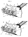
- Fig. 2 is also shown in two figure parts A, B, a second embodiment of the invention, in which the trigger pin is not, as in the case of Fig. 1 , Constant diameter, but axially stepped in diameter is formed.
- This stepped tripping pin 1 ' has a central portion 1'a which is tuned to the diameter of the bore 2a in the tension rod 2 and to which adjoin portions 1'b of smaller diameter on both sides, the right portion 1'b and on the left a larger diameter portion 1'c in the bearing block 3, the bearing points of the tripping pin 1 'form.
- the bore 2a in the tension rod 2 has a slot 2b whose width is tuned to the narrower diameter of the journal portions 1'b. Otherwise, the shows FIG. 2 already in Fig. 1 illustrated components.
- the trigger pin 5b and the trigger pin 1 ' may be two separate parts.
- Fig. 3 in two parts A, B a third embodiment of the holding and releasing device according to the invention is shown, in which the actuator 5 is formed pin-pulling and the trigger pin 1 "is firmly connected to the retractable pin Fig. 3 also already in Fig. 1 illustrated components.
- the triggering pin 1 has a continuously constant diameter, adapted to the opening 2a of the tension rod 2.
- the opening 2a is positively connected to the triggering pin 1", which is an extension of the tension rod 2 and thus of the rollover body prevented. If the tripping pin is retracted by the actuator 5 in a sensor-controlled manner (FIG. Part B), the tension rod 2 is released and can extend.
Landscapes
- Engineering & Computer Science (AREA)
- Mechanical Engineering (AREA)
- Automotive Seat Belt Assembly (AREA)
- Seats For Vehicles (AREA)
Claims (10)
- Système de protection anti-renversement pour voitures particulières, avec un corps anti-renversement retenu de façon déplaçable, qui peut être retenu à l'état normal contre la force d'au moins un ressort de pression d'entraînement (6) précontraint par un dispositif de retenue dans une position de repos inférieure, rentrée, et qui peut être amené dans une position de protection, supérieure, verrouillée, par le déblocage du dispositif de retenue par la force de ressort du ressort de pression d'entraînement, dans lequel le dispositif de retenue présente un élément de retenue relié au corps anti-renversement et un élément de déclenchement se trouvant en relation fonctionnelle mécanique déblocable avec celui-ci à un actionneur commandé par capteur et solidaire du véhicule, caractérisé en ce que l'élément de retenue est formé par une barre de traction (2) reçue à l'intérieur du ressort de pression d'entraînement et ayant un alésage (2a) à l'extrémité côté déclenchement, et l'élément de déclenchement est formé par une cheville de déclenchement (1, 1', 1"), retenue dans un palier (3) solidaire du véhicule avec deux points d'appui, pouvant être reçue par complémentarité de forme dans l'alésage (2a) de la barre de traction (2) entre les deux points d'appui, et pouvant être déplacée longitudinalement par l'actionneur (5) dans le palier (3) d'une position à effet de retenue à une position à effet de déblocage.
- Système de protection anti-renversement selon la revendication 1, caractérisé en ce que la cheville de déclenchement (1, 1') est un composant séparé.
- Système de protection anti-renversement selon la revendication 1, caractérisé en ce que la cheville de déclenchement (1', 1") est reliée solidement à l'élément de mouvement (5b) de l'actionneur (5).
- Système de protection anti-renversement selon la revendication 2, caractérisé en ce que la cheville de déclenchement séparée (1) se trouve en relation fonctionnelle avec l'élément de mouvement (5b) de l'actionneur (5) de telle sorte que lors de l'activation de l'actionneur (5), elle peut être expulsée de son dispositif de retenue (3) solidaire du véhicule de la relation fonctionnelle de retenue à la relation fonctionnelle de déblocage.
- Système de protection anti-renversement selon la revendication 2 ou 3, caractérisé en ce que la cheville de déclenchement (1', 1") est disposée en pouvant être avancée ou reculée en alternance dans la position à effet de déblocage par l'élément de mouvement de l'actionneur (5).
- Système de protection anti-renversement selon les revendications 3 et 5, caractérisé en ce que l'agencement est réalisé de telle sorte que lors de l'activation de l'actionneur, la cheville de déclenchement (1") peut être sortie complètement de son dispositif de retenue (3) solidaire du véhicule de la relation fonctionnelle de retenue à la relation fonctionnelle de déblocage.
- Système de protection anti-renversement selon la revendication 5, caractérisé en ce que la cheville de déclenchement (1') présente entre ses deux points d'appui différentes sections (1'a, 1'b) spécifiant la position à effet de retenue et la position à effet de déblocage en conjonction avec une fente de déblocage (2b) à l'ouverture (2a) de la barre de traction (2).
- Système de protection anti-renversement selon l'une quelconque des revendications 1 à 7, caractérisé en ce que la cheville de déclenchement (1, 1', 1") ainsi que ses points d'appui et l'alésage associé (2a) sont réalisés de façon circulaire dans la barre de traction (2).
- Système de protection anti-renversement selon la revendication 8, caractérisé en ce que le diamètre de la cheville de déclenchement (1, 1") est constant sur sa longueur axiale.
- Système de protection anti-renversement selon les revendications 7 et 8, caractérisé en ce que la cheville de déclenchement (1') possède au moins une section (1'a) spécifiant la mise en prise à effet de retenue et ayant un grand diamètre correspondant à celui de l'alésage (2a) dans la barre de traction (2), et au moins une section (1'b) décalée par rapport à celle-ci, spécifiant la mise en prise à effet de déblocage et ayant un diamètre plus petit, et la barre de traction (2) présente à son extrémité côté déclenchement la fente de déblocage (2b) menant à l'alésage (2a) et dont la largeur est supérieure au diamètre plus petit, mais inférieure au diamètre plus grand de la cheville de déclenchement (1').
Applications Claiming Priority (2)
| Application Number | Priority Date | Filing Date | Title |
|---|---|---|---|
| DE10342488 | 2003-09-10 | ||
| DE2003142488 DE10342488B4 (de) | 2003-09-10 | 2003-09-10 | Überrollschutzsystem für Kraftfahrzeuge mit einem ausfahrbaren Überrollkörper |
Publications (2)
| Publication Number | Publication Date |
|---|---|
| EP1514740A1 EP1514740A1 (fr) | 2005-03-16 |
| EP1514740B1 true EP1514740B1 (fr) | 2009-03-25 |
Family
ID=34129811
Family Applications (1)
| Application Number | Title | Priority Date | Filing Date |
|---|---|---|---|
| EP04021072A Expired - Lifetime EP1514740B1 (fr) | 2003-09-10 | 2004-09-04 | Dispositif d'arceau de sécurité pour véhicules avec un arceau déployable |
Country Status (2)
| Country | Link |
|---|---|
| EP (1) | EP1514740B1 (fr) |
| DE (2) | DE10342488B4 (fr) |
Families Citing this family (1)
| Publication number | Priority date | Publication date | Assignee | Title |
|---|---|---|---|---|
| DE102011013255B4 (de) | 2011-03-07 | 2024-01-04 | Zf Airbag Germany Gmbh | Entriegelungsvorrichtung |
Citations (1)
| Publication number | Priority date | Publication date | Assignee | Title |
|---|---|---|---|---|
| US3561806A (en) * | 1968-09-19 | 1971-02-09 | Quong Non Tse | Vehicle safety system |
Family Cites Families (5)
| Publication number | Priority date | Publication date | Assignee | Title |
|---|---|---|---|---|
| DE4342400C2 (de) * | 1993-08-03 | 2002-06-13 | Ise Gmbh | Überrollbügeleinrichtung |
| DE4342401B4 (de) * | 1993-12-13 | 2004-09-30 | Ise Innomotive Systems Europe Gmbh | Überrollbügel für Kraftfahrzeuge |
| DE19838989C1 (de) * | 1998-08-27 | 1999-11-11 | Ise Gmbh | Überroll-Schutzvorrichtung |
| DE10012573C1 (de) * | 2000-03-15 | 2001-03-01 | Ise Gmbh | Haltevorrichtung für den Überrollkörper eines Überrollschutzsystems |
| WO2002004259A1 (fr) * | 2000-07-07 | 2002-01-17 | The Government Of The United States Of America As Represented By The Secretary Of The Department Of Health And Human Services, Centers For Disease Control And Prevention | Systeme de protection en cas de renversement a deploiement automatique |
-
2003
- 2003-09-10 DE DE2003142488 patent/DE10342488B4/de not_active Expired - Fee Related
-
2004
- 2004-09-04 EP EP04021072A patent/EP1514740B1/fr not_active Expired - Lifetime
- 2004-09-04 DE DE200450009205 patent/DE502004009205D1/de not_active Expired - Fee Related
Patent Citations (1)
| Publication number | Priority date | Publication date | Assignee | Title |
|---|---|---|---|---|
| US3561806A (en) * | 1968-09-19 | 1971-02-09 | Quong Non Tse | Vehicle safety system |
Also Published As
| Publication number | Publication date |
|---|---|
| DE502004009205D1 (de) | 2009-05-07 |
| DE10342488A1 (de) | 2005-05-04 |
| DE10342488B4 (de) | 2006-04-27 |
| EP1514740A1 (fr) | 2005-03-16 |
Similar Documents
| Publication | Publication Date | Title |
|---|---|---|
| DE102005059910B3 (de) | Überrollschutzsystem für Kraftfahrzeuge mit einem faltbaren Überrollbügel | |
| DE102007005517B4 (de) | Überrollschutzsystem für Kraftfahrzeuge mit einem aktiv aufstellbaren Überrollkörper mit integriertem Deformationselement | |
| DE19750693C2 (de) | Ausfahrbarer Überrollbügel für Kraftfahrzeuge | |
| EP1736373B1 (fr) | Système de protection pour le capotage d'un véhicule automobile | |
| EP1095823B1 (fr) | Dispositif de protection contre le retournement pour véhicules | |
| DE19925520C1 (de) | Überroll-Schutzsystem für Kraftfahrzeuge | |
| DE102006028664B4 (de) | Überrollschutzsystem für ein Kraftfahrzeug | |
| EP1547873B1 (fr) | système d'arceau de sécurité pour véhicule avec arceau déployable | |
| EP1514740B1 (fr) | Dispositif d'arceau de sécurité pour véhicules avec un arceau déployable | |
| EP1227011B1 (fr) | Système d'arceau de sécurité pour véhicules automobiles | |
| EP1736371B1 (fr) | Véhicule avec système de protection en cas de retournement | |
| DE102007006768A1 (de) | Überrollschutzsystem für Kraftfahrzeuge mit einem sensorgesteuert aktiv aufstellbaren Überrollkörper | |
| DE102005028879B4 (de) | Überrollschutzsystem für ein Kraftfahrzeug | |
| DE102005028966B4 (de) | Kraftfahrzeug mit einem Überrollschutzsystem an einer Fahrzeugquerwand | |
| DE102009006876A1 (de) | Laderaumabdeckung | |
| DE102005028964B4 (de) | Überrollschutzsystem für ein Kraftfahrzeug | |
| EP1582420B1 (fr) | Systéme de protection pour capotage avec un arceau deployable | |
| DE102007013954A1 (de) | Überrollschutzsystem für Kraftfahrzeuge mit einem sensorgesteuert aktiv aufstellbaren Überrollkörper | |
| DE10103245C1 (de) | Überrollschutzsystem für Kraftfahrzeuge | |
| EP1955907B1 (fr) | Système de protection avec arceau de sécurité pour des véhicules automobiles | |
| DE102006000909B4 (de) | Überrollschutzsystem für ein Cabriolet-Fahrzeug mit gekrümmtem Überrollkörper | |
| EP2384939B1 (fr) | Système de protection contre les tonneaux pour des véhicules automobiles | |
| DE102006013913B4 (de) | Schutzvorrichtung in Kraftfahrzeugen zum Personenschutz | |
| DE102006002476B4 (de) | Überrollschutzsystem für ein Kraftfahrzeug | |
| DE102005028962A1 (de) | Überrollschutzsystem für ein Kraftfahrzeug |
Legal Events
| Date | Code | Title | Description |
|---|---|---|---|
| PUAI | Public reference made under article 153(3) epc to a published international application that has entered the european phase |
Free format text: ORIGINAL CODE: 0009012 |
|
| AK | Designated contracting states |
Kind code of ref document: A1 Designated state(s): AT BE BG CH CY CZ DE DK EE ES FI FR GB GR HU IE IT LI LU MC NL PL PT RO SE SI SK TR |
|
| AX | Request for extension of the european patent |
Extension state: AL HR LT LV MK |
|
| 17P | Request for examination filed |
Effective date: 20050428 |
|
| AKX | Designation fees paid |
Designated state(s): DE ES FR GB IT |
|
| RAP1 | Party data changed (applicant data changed or rights of an application transferred) |
Owner name: ISE AUTOMOTIVE GMBH |
|
| GRAP | Despatch of communication of intention to grant a patent |
Free format text: ORIGINAL CODE: EPIDOSNIGR1 |
|
| GRAS | Grant fee paid |
Free format text: ORIGINAL CODE: EPIDOSNIGR3 |
|
| GRAA | (expected) grant |
Free format text: ORIGINAL CODE: 0009210 |
|
| AK | Designated contracting states |
Kind code of ref document: B1 Designated state(s): DE ES FR GB IT |
|
| REG | Reference to a national code |
Ref country code: GB Ref legal event code: FG4D Free format text: NOT ENGLISH |
|
| REF | Corresponds to: |
Ref document number: 502004009205 Country of ref document: DE Date of ref document: 20090507 Kind code of ref document: P |
|
| PG25 | Lapsed in a contracting state [announced via postgrant information from national office to epo] |
Ref country code: ES Free format text: LAPSE BECAUSE OF FAILURE TO SUBMIT A TRANSLATION OF THE DESCRIPTION OR TO PAY THE FEE WITHIN THE PRESCRIBED TIME-LIMIT Effective date: 20090706 |
|
| PGFP | Annual fee paid to national office [announced via postgrant information from national office to epo] |
Ref country code: GB Payment date: 20090922 Year of fee payment: 6 |
|
| PLBE | No opposition filed within time limit |
Free format text: ORIGINAL CODE: 0009261 |
|
| STAA | Information on the status of an ep patent application or granted ep patent |
Free format text: STATUS: NO OPPOSITION FILED WITHIN TIME LIMIT |
|
| 26N | No opposition filed |
Effective date: 20091229 |
|
| PG25 | Lapsed in a contracting state [announced via postgrant information from national office to epo] |
Ref country code: DE Free format text: LAPSE BECAUSE OF NON-PAYMENT OF DUE FEES Effective date: 20100401 |
|
| PG25 | Lapsed in a contracting state [announced via postgrant information from national office to epo] |
Ref country code: IT Free format text: LAPSE BECAUSE OF FAILURE TO SUBMIT A TRANSLATION OF THE DESCRIPTION OR TO PAY THE FEE WITHIN THE PRESCRIBED TIME-LIMIT Effective date: 20090325 |
|
| GBPC | Gb: european patent ceased through non-payment of renewal fee |
Effective date: 20100904 |
|
| REG | Reference to a national code |
Ref country code: FR Ref legal event code: ST Effective date: 20110531 |
|
| PG25 | Lapsed in a contracting state [announced via postgrant information from national office to epo] |
Ref country code: FR Free format text: LAPSE BECAUSE OF NON-PAYMENT OF DUE FEES Effective date: 20100930 |
|
| PG25 | Lapsed in a contracting state [announced via postgrant information from national office to epo] |
Ref country code: GB Free format text: LAPSE BECAUSE OF NON-PAYMENT OF DUE FEES Effective date: 20100904 |
|
| PGFP | Annual fee paid to national office [announced via postgrant information from national office to epo] |
Ref country code: FR Payment date: 20091005 Year of fee payment: 6 |
|
| REG | Reference to a national code |
Ref country code: DE Ref legal event code: R081 Ref document number: 502004009205 Country of ref document: DE Owner name: METALSA AUTOMOTIVE GMBH, DE Free format text: FORMER OWNER: ISE AUTOMOTIVE GMBH, 51702 BERGNEUSTADT, DE Effective date: 20130812 |