EP1514740B1 - Roll-over protection device for vehicles with an expandable rollbar - Google Patents
Roll-over protection device for vehicles with an expandable rollbar Download PDFInfo
- Publication number
- EP1514740B1 EP1514740B1 EP04021072A EP04021072A EP1514740B1 EP 1514740 B1 EP1514740 B1 EP 1514740B1 EP 04021072 A EP04021072 A EP 04021072A EP 04021072 A EP04021072 A EP 04021072A EP 1514740 B1 EP1514740 B1 EP 1514740B1
- Authority
- EP
- European Patent Office
- Prior art keywords
- roll
- release
- actuator
- protection system
- pin
- Prior art date
- Legal status (The legal status is an assumption and is not a legal conclusion. Google has not performed a legal analysis and makes no representation as to the accuracy of the status listed.)
- Expired - Fee Related
Links
Images


Classifications
-
- B—PERFORMING OPERATIONS; TRANSPORTING
- B60—VEHICLES IN GENERAL
- B60R—VEHICLES, VEHICLE FITTINGS, OR VEHICLE PARTS, NOT OTHERWISE PROVIDED FOR
- B60R21/00—Arrangements or fittings on vehicles for protecting or preventing injuries to occupants or pedestrians in case of accidents or other traffic risks
- B60R21/02—Occupant safety arrangements or fittings, e.g. crash pads
- B60R21/13—Roll-over protection
- B60R2021/132—Roll bars for convertible vehicles
- B60R2021/134—Roll bars for convertible vehicles movable from a retracted to a protection position
- B60R2021/135—Roll bars for convertible vehicles movable from a retracted to a protection position automatically during an accident
Definitions
- the invention relates to a rollover protection system for persons motor vehicles, with a movably supported roll body which is durable in the normal state against the force of at least one biased drive compression spring by a holding device in a lower, retracted rest position, and releasing the holding device by the spring force the drive compression spring in a locked upper, protective position can be brought, wherein the holding device has a connected to the rollover body holding member and thus standing in releasable mechanical operative connection release member on a vehicle-mounted, sensor-controlled actuator.
- Such rollover protection systems are used to protect the occupants in motor vehicles without protective roof, typically in convertibles or sports cars in a rollover, since the vehicle will roll over the rollover body.
- rollover protection systems typically have a guided in a vehicle-fixed guide body U-shaped or formed from a profile body rollover body, wherein the guide body is mounted in a cassette housing.
- This rollover body is held in the normal state against the biasing force of a drive compression spring by a holding device in a lower rest position, and is in the rollover case, sensor controlled releasing the holding device, by the spring force of the drive compression spring in an upper, protective position can be brought, wherein a engaged locking device, the re-entry lock, prevents the rollover bar from being pushed in.
- each vehicle seat is typically associated with a cassette, in particular in the front vehicle seats.
- the cassettes can also be integrated in a rear wall unit.
- Such a cassette construction of a roll bar protection system with a U-shaped roll bar shows, for example, the DE 43 42 400 A1 ; an alternative cassette construction with a rollover body in the form of a profile body shows in particular the DE 198 38 989 C1 ,
- the aforementioned holding device for the extendable rollover body typically has a holding member attached to the rollover body, which is in detachable mechanical operative connection with a trigger member on a vehicle-mounted, sensor-controlled release system, the actuator, by a trigger magnet, the so-called crash magnets, or by a pyrotechnic trigger member, is formed.
- the holding member is in many constructions, eg according to DE 100 12 573 C1 formed as a retaining bolt, which is connected, for example via a rocker or other tolerance compensating, connecting element with the rollover body, and with a trigger member forming the pawl of the actuator, preferably a double pawl actuator after DE 197 50 693 C1 , is in releasable operative engagement.
- the invention has for its object to form the above-described rollover protection system with respect to the holding device so that when triggered less frictional resistance than in the known case to overcome and there is no risk of Zuschverriegelns.
- a rollover protection system for passenger vehicles with a movable retained Rollbar which is durable in the normal state against the force of at least one biased drive compression spring by a holding device in a lower, retracted rest position, and can be brought under release of the holding device by the spring force of the drive compression spring in a locked upper, protective position, wherein the holding device a holding member connected to the rollover body and thus releasable according to the invention, characterized in that the holding member held by a recorded in the interior of the drive compression spring pull rod with a bore on the trigger side end and the trigger member by one in a vehicle-mounted storage with two bearing points Erten , can be received in a form-fitting manner in the bore of the tension rod between the two bearing points and is formed by the actuator in the bearing of a holding, in a releasing operative position longitudinally displaceable tripping pin.
- the holding down of the rollover body takes place directly, i. without intermediate links such as pawls, etc.
- To trigger only the frictional resistance between the trigger pin and its storage in its axial movement of the holding in the releasing operative position has overcome who the. Furthermore, there is no risk of remindverriegelns as in pawls systems.
- the DE 43 42 401 A1 shows in addition to an embodiment of a Hal tesystems with a pawl as an intermediate member, a holding system in which the release pin of a vehicle-fixed actuator is in releasable operative connection with the hook part of a trained as a tow hook th holding member.
- the use of a towing hook in contrast to a use of a tension rod, does not make it possible to use an already existing component of the rollover protection system as a holding member.
- the provided in the holding system according to the invention bore in the pull rod ensures a positive reception and thus a correspondingly very stable support of the tripping pin of the actuator, which is required to avoid unwanted false triggering due to vibration and vibration and to ensure a rattle-free mount, which is not given in the known case by the sole adhesion.
- the actuator attached to the vehicle which in the held state strong shear forces on the holder of the release pin in the actuator, which can cause jamming of the pin in the actuator. This is avoided in the case of the invention by the separate vehicle-fixed bearing and the tripping pin.
- the invention therefore provides a holding system which is not susceptible to tolerances, and which has a very good and safe long-term behavior and high reliability under all operating conditions.
- the WO 02/04259 A1 shows a rollover protection system for a tractor, with a solid U-shaped roll bar, the two strong legs tubes, each mounted in a vehicle-mounted standpipe erectable and connected at the head via a tubular cross-yoke, having.
- the leg tubes are held down against the force of a drive compression spring by a respective holding device.
- Each holding device has on the associated leg tube at two opposite positions in each case a pyrotechnic actuator with a retractable release pin, which is in the rest position of the roll bar with a holding member forming blind hole in the associated leg tube in holding operative connection.
- This elaborately constructed holding principle is not suitable for passenger car rollover protection systems, regardless of the question of safe synchronous tripping of four actuators.
- the trigger pin can be formed in various ways. According to a first embodiment, it may be a separate, ie a loose component independent of the actuator. However, it can also be firmly, in particular in one piece, connected to the moving element of the actuator according to another embodiment.
- the cross section of the tripping pin and its associated bearing points and the bore in the pull rod are preferably circular, but may also have a different geometric configuration.
- the design is made with a separate trigger pin so that the separate trigger pin is in operative connection with the moving member of the actuator that he is ejected when activating the actuator from its vehicle-mounted bracket of the holding in the releasing operative connection.
- the release pin with the moving element of the actuator is alternatively arranged forward or backward displaceable in the releasing operative position.
- the trigger pin may be a separate component or fixedly connected to the actuator.
- the design is preferably such that the trigger pin when activating the actuator is completely withdrawn from its vehicle-mounted holder from the holding into the releasing operative connection.
- the design can also be made such that the release pin between its two bearing points different, the holding and releasing operative position predetermining sections in conjunction with a release slot at the opening of the tie rod.
- the diameter of the trigger pin is circular
- the design of the system is suitably made such that the trigger pin at least one, the holding action predetermining section with a large, that of the bore in the tie rod corresponding diameter and at least one thereof, the releasing operative engagement predetermining section has smaller diameter, and the pull rod has at its trigger-side end leading to the bore release slot whose width is greater than the smaller diameter, but smaller than the larger diameter of the tripping pin.
- the diameter of the tripping pin is constant over its axial length.
- Fig. 1 is in two parts of the figure A, B, a first embodiment of the holding device according to the invention with an expelled by an actuator, diameter constant trigger pin 1 shown as a trigger member.
- the figure part A shows the ground state of the rollover protection system, in which the (not shown) rollover body is held down against the force of a central drive compression spring 6, while the figure part B shows the tripped state.
- the holding device has as a holding member on a pull rod 2 which is mechanically connected at one end in a suitable manner with the rollover body (not shown).
- the tension rod 2 At the free end, the tension rod 2 a circular opening (bore) 2 a, which has a diameter which is larger by a small amount than the diameter of the tripping pin 1, to ensure a non-clamping seat of the tension rod 2 on the tripping pin 1.
- the trigger pin 1 is mounted longitudinally displaceable in a vehicle-mounted bearing block 3. Also fixed to the vehicle is a holder 4 is mounted for the actuator, which is formed in the illustrated embodiment by a pyro element 5 containing a squib, which is sensor-controlled ignited via a cable 5a.
- the figures also show the vehicle-fixed Aufstellfeder 6 in the form of a coil spring, through the interior of the tension rod 2 can come into operative engagement with the tripping pin 1 via an opening in the bearing block 3.
- the pull rod 2 which also serves as a spring guide pin, over its length, and engages with the free, upper end of the rollover body.
- a so-called trigger magnet or another fast drive system can be provided hydraulically, pneumatically, by motor.
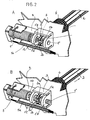
- Fig. 2 is also shown in two figure parts A, B, a second embodiment of the invention, in which the trigger pin is not, as in the case of Fig. 1 , Constant diameter, but axially stepped in diameter is formed.
- This stepped tripping pin 1 ' has a central portion 1'a which is tuned to the diameter of the bore 2a in the tension rod 2 and to which adjoin portions 1'b of smaller diameter on both sides, the right portion 1'b and on the left a larger diameter portion 1'c in the bearing block 3, the bearing points of the tripping pin 1 'form.
- the bore 2a in the tension rod 2 has a slot 2b whose width is tuned to the narrower diameter of the journal portions 1'b. Otherwise, the shows FIG. 2 already in Fig. 1 illustrated components.
- the trigger pin 5b and the trigger pin 1 ' may be two separate parts.
- Fig. 3 in two parts A, B a third embodiment of the holding and releasing device according to the invention is shown, in which the actuator 5 is formed pin-pulling and the trigger pin 1 "is firmly connected to the retractable pin Fig. 3 also already in Fig. 1 illustrated components.
- the triggering pin 1 has a continuously constant diameter, adapted to the opening 2a of the tension rod 2.
- the opening 2a is positively connected to the triggering pin 1", which is an extension of the tension rod 2 and thus of the rollover body prevented. If the tripping pin is retracted by the actuator 5 in a sensor-controlled manner (FIG. Part B), the tension rod 2 is released and can extend.
Description
Die Erfindung bezieht sich auf ein Überrollschutzsystem für Personen Kraftfahrzeuge, mit einem verfahrbar gehalterten Überrollkörper, der im Normalzustand gegen die Kraft von mindestens einer vorgespannten Antriebs-Druckfeder durch eine Haltevorrichtung in einer unteren, eingefahrenen Ruhelage haltbar ist, und unter Lösen der Haltevorrichtung durch die Federkraft der Antriebs-Druckfeder in eine verriegelte obere, schützende Stellung bringbar ist, wobei die Haltevorrichtung ein mit dem Überrollkörper verbundenes Halteglied und ein damit in lösbarer mechanischer Wirkverbindung stehendes Auslöseglied an einem fahrzeugfesten, sensorgesteuerten Aktuator aufweist.The invention relates to a rollover protection system for persons motor vehicles, with a movably supported roll body which is durable in the normal state against the force of at least one biased drive compression spring by a holding device in a lower, retracted rest position, and releasing the holding device by the spring force the drive compression spring in a locked upper, protective position can be brought, wherein the holding device has a connected to the rollover body holding member and thus standing in releasable mechanical operative connection release member on a vehicle-mounted, sensor-controlled actuator.
Derartige Überrollschutzsysteme dienen zum Schutz der Insassen in Kraftfahrzeugen ohne schützendes Dach, typischerweise in Cabriolets oder Sportwagen bei einem Überschlag, da das Fahrzeug über den Überrollkörper abrollen wird.Such rollover protection systems are used to protect the occupants in motor vehicles without protective roof, typically in convertibles or sports cars in a rollover, since the vehicle will roll over the rollover body.
Es ist dabei bekannt, einen die gesamte Fahrzeugbreite überspannenden, fest installierten Überrollbügel vorzusehen. Bei dieser Lösung wird der erhöhte Luftwiderstand und das Auftreten von Fahrgeräuschen als nachteilig empfunden, abgesehen von der Beeinträchtigung des Fahrzeugaussehens.It is known to provide a full vehicle width spanning, permanently installed roll bar. In this solution, the increased air resistance and the occurrence of driving noise is perceived as disadvantageous, apart from the impairment of the vehicle appearance.
Es ist auch bekannt, jedem Fahrzeugsitz einen höhenunveränderlich fest installierten Überrollbügel zuzuordnen. Diese Lösung wird typischerweise bei Sportwagen zur Unterstreichung des sportlichen Aussehens eingesetzt.It is also known to assign each vehicle seat a höhenunveränderlich permanently installed roll bar. This solution is typically used on sports cars to underline the sporty appearance.
Weit verbreitet bei Cabriolets sind konstruktive Lösungen, bei denen der Überrollkörper im Normalzustand eingefahren ist, und im Gefahrenfall, also bei einem drohenden Überschlag, schnell in eine schützende Position ausgefahren wird, um zu verhindern, dass die Fahrzeuginsassen durch das sich überschlagende Fahrzeug erdrückt werden.Widely used in convertibles are constructive solutions in which the rollover body is retracted in the normal state, and in case of danger, so in an impending rollover, is quickly extended to a protective position to prevent the vehicle occupants are crushed by the overturning vehicle.
Von einem derartigen verfahrbaren Überrollkörper geht auch die Erfindung aus.From such a movable rollover body is also the invention.
Diese Überrollschutzsysteme weisen typischerweise einen in einem fahrzeugfesten Führungskörper geführten U-förmigen oder aus einem Profilkörper gebildeten Überrollkörper, auf, wobei der Führungskörper in einem Kassetten-Gehäuse befestigt ist. Dieser Überrollkörper wird im Normalzustand gegen die Vorspannkraft einer Antriebs-Druckfeder durch eine Haltevorrichtung in einer unteren Ruhelage gehalten, und ist im Überschlagfall, sensorgesteuert unter Lösen der Haltevorrichtung, durch die Federkraft der Antriebs-Druckfeder in eine obere, schützende Stellung bringbar, wobei eine dann in Wirkeingriff tretende Verriegelungseinrichtung, die Wiedereinfahrsperre, ein Eindrücken des Überrollbügels verhindert. Dabei ist typischerweise jedem Fahrzeugsitz eine Kassette zugeordnet, insbesondere bei den vorderen Fahrzeugsitzen. Im Fond können die Kassetten auch in einer Rückwand-Baueinheit integriert sein.These rollover protection systems typically have a guided in a vehicle-fixed guide body U-shaped or formed from a profile body rollover body, wherein the guide body is mounted in a cassette housing. This rollover body is held in the normal state against the biasing force of a drive compression spring by a holding device in a lower rest position, and is in the rollover case, sensor controlled releasing the holding device, by the spring force of the drive compression spring in an upper, protective position can be brought, wherein a engaged locking device, the re-entry lock, prevents the rollover bar from being pushed in. In this case, each vehicle seat is typically associated with a cassette, in particular in the front vehicle seats. In the rear, the cassettes can also be integrated in a rear wall unit.
Eine derartige Kassetten-Konstruktion eines Überrollbügelschutzsystems mit einem U-förmigen Überrollbügel zeigt beispielsweise die
Die vorgenannte Haltevorrichtung für die ausfahrbaren Überrollkörper besitzt typischerweise ein am Überrollkörper befestigtes Halteglied, das in lösbarer mechanischer Wirkverbindung mit einem Auslöseglied an einem fahrzeugfesten, sensorgesteuerten Auslösesystem, dem Aktuator, steht, der durch einen Auslösemagneten, den sogenannten Crashmagneten, oder durch ein pyrotechnisches Auslöseglied, gebildet ist. Das Halteglied ist bei zahlreichen Konstruktionen, z.B. gemäß
Bei einem derartigen Klinken-Haltesystem muss zur Auslösung des Überrollkörpers nicht nur der Reibwiderstand zwischen Klinke und Haltebolzen überwunden werden, sondern auch Reibkräfte innerhalb des Auslösegliedes des Aktuators. Ferner besteht typbedingt bei Klinkensystemen die Gefahr des Zurückverriegelns.In such a pawl-holding system not only the frictional resistance between the pawl and retaining pin must be overcome to trigger the rollover body, but also frictional forces within the trigger member of the actuator. Furthermore, there is a risk of Rückverriegelns in latch systems due to type.
Der Erfindung liegt die Aufgabe zugrunde, das eingangs bezeichnete Überrollschutzsystem hinsichtlich der Haltevorrichtung so auszubilden, dass bei einer Auslösung weniger Reibwiderstand als im bekannten Fall zu überwinden ist und keine Gefahr des Zurückverriegelns besteht.The invention has for its object to form the above-described rollover protection system with respect to the holding device so that when triggered less frictional resistance than in the known case to overcome and there is no risk of Zurückverriegelns.
Die Lösung dieser Aufgabe gelingt bei einem Überrollschutzsystem für Personenkraftfahrzeuge mit einem verfahrbar gehalterten Überrollbügel, der im Normalzustand gegen die Kraft von mindestens einer vorgespannten Antriebs-Druckfeder durch eine Haltevorrichtung in einer unteren, eingefahrenen Ruhelage haltbar ist, und unter Lösen der Haltevorrichtung durch die Federkraft der Antriebs-Druckfeder in eine verriegelte obere, schützende Stellung bringbar ist, wobei die Haltevorrichtung ein mit dem Überrollkörper verbundenes Halteglied und ein damit in lösbarer mechanischer Wirkverbindung stehendes Auslöseglied an einem fahrzeugfesten, sensorgesteuerten Aktuator aufweist, gemäß der Erfindung dadurch, dass dass das Halteglied durch einen im Inneren der Antriebs-Druckfeder aufgenommenen Zugstab mit einer Bohrung am auslöseseitigen Ende und das Auslöseglied durch einen in einer fahrzeugfesten Lagerung mit zwei Lagerstellen gehalterten, formschlüssig in der Bohrung des Zugstabes zwischen beiden Lagerstellen aufnehmbaren und durch den Aktuator in der Lagerung aus einer haltenden, in eine freigebende Wirkstellung längs verschiebbaren Auslösezapfen gebildet ist.The solution to this problem is achieved in a rollover protection system for passenger vehicles with a movable retained Rollbar, which is durable in the normal state against the force of at least one biased drive compression spring by a holding device in a lower, retracted rest position, and can be brought under release of the holding device by the spring force of the drive compression spring in a locked upper, protective position, wherein the holding device a holding member connected to the rollover body and thus releasable according to the invention, characterized in that the holding member held by a recorded in the interior of the drive compression spring pull rod with a bore on the trigger side end and the trigger member by one in a vehicle-mounted storage with two bearing points Erten , can be received in a form-fitting manner in the bore of the tension rod between the two bearing points and is formed by the actuator in the bearing of a holding, in a releasing operative position longitudinally displaceable tripping pin.
Bei dem erfindungsgemäßen Haltesystem erfolgt das Niederhalten des Überrollkörpers direkt, d.h. ohne Zwischenglieder wie Klinken usw. Zur Auslösung muss nur der Reibwiderstand zwischen dem Auslösezapfen und seiner Lagerung bei seiner axialen Bewegung von der haltenden in die freigebende Wirkstellung überwunden wer den. Ferner besteht keine Gefahr des Zurückverriegelns wie bei Klinkensystemen.In the holding system according to the invention, the holding down of the rollover body takes place directly, i. without intermediate links such as pawls, etc. To trigger only the frictional resistance between the trigger pin and its storage in its axial movement of the holding in the releasing operative position has overcome who the. Furthermore, there is no risk of Rückverriegelns as in pawls systems.
Die
Die Verwendung eines Zughakens ermöglicht es, im Gegensatz bei einer Verwendung eines Zugstabes, nicht, ein ohnehin vorhandenes Bauteil des Überrollschutzsystems als Halteglied zu benutzen. Die bei dem erfindungsgemäßen Haltesystem vorgesehene Bohrung im Zugstab gewährleistet eine formschlüssige Aufnahme und damit eine entsprechende sehr stabile Halterung des Auslösezapfens des Aktuators, die erforderlich ist, um ungewollte Fehlauslösungen auf Grund von Schwingungen und Vibrationen zu vermeiden sowie um eine klapperfreie Halterung zu gewährleisten, was im bekannten Fall durch den alleinigen Kraftschluss nicht gegeben ist. Schließlich ist im bekannten Fall nur der Aktuator fahrzeugfest angebracht, wodurch im gehaltenen Zustand starke Scherkräfte an der Halterung des Auslösestiftes im Aktuator entstehen, die ein Verklemmen des Stiftes im Aktuator auslösen können. Dies wird im Fall der Erfindung durch die gesonderte fahrzeugfeste Lagerund des Auslösezapfens vermieden.The use of a towing hook, in contrast to a use of a tension rod, does not make it possible to use an already existing component of the rollover protection system as a holding member. The provided in the holding system according to the invention bore in the pull rod ensures a positive reception and thus a correspondingly very stable support of the tripping pin of the actuator, which is required to avoid unwanted false triggering due to vibration and vibration and to ensure a rattle-free mount, which is not given in the known case by the sole adhesion. Finally, in the known case, only the actuator attached to the vehicle, which in the held state strong shear forces on the holder of the release pin in the actuator, which can cause jamming of the pin in the actuator. This is avoided in the case of the invention by the separate vehicle-fixed bearing and the tripping pin.
Die Erfindung schafft daher ein Haltesystem das nicht anfällig bezüglich Toleranzen ist, und das ein sehr gutes sowie sicheres Langzeitverhalten und eine hohe Funktionssicherheit unter allen Betriebsbedingungen besitzt.The invention therefore provides a holding system which is not susceptible to tolerances, and which has a very good and safe long-term behavior and high reliability under all operating conditions.
Die
Dieses aufwändig konstruierte Halte-Prinzip ist, unabhängig von der Frage der sicheren synchronen Auslösung von vier Aktuatoren, nicht für Überrollschutzsysteme für Personenkraftwagen geeignet.The
This elaborately constructed holding principle is not suitable for passenger car rollover protection systems, regardless of the question of safe synchronous tripping of four actuators.
Der Auslösezapfen kann auf verschiedene Weise ausgebildet sein. Nach einer ersten Ausführungsform kann er ein separates, d.h. ein von dem Aktuator unabhängiges, loses Bauteil sein. Er kann aber auch nach einer anderen Ausführungsform fest, insbesondere einstückig, mit dem Bewegungselement des Aktuators verbunden sein.The trigger pin can be formed in various ways. According to a first embodiment, it may be a separate, ie a loose component independent of the actuator. However, it can also be firmly, in particular in one piece, connected to the moving element of the actuator according to another embodiment.
Der Querschnitt des Auslösezapfens sowie seine zugehörigen Lagerstellen und die Bohrung im Zugstab sind vorzugsweise kreisrund ausgebildet, können aber auch eine andere geometrische Konfiguration aufweisen.The cross section of the tripping pin and its associated bearing points and the bore in the pull rod are preferably circular, but may also have a different geometric configuration.
Je nach Bauart des Haltesystems wird der Auslösebolzen im Crash-Fall von dem Aktuator aus dem formschlüssigen Wirkeingriff mit der Bohrung in dem Zugstab wahlweise gezogen, gedrückt oder gestoßen, wie es in den Unteransprüchen näher gekennzeichnet ist.Depending on the design of the holding system of the trigger pin is pulled in the event of a crash of the actuator from the positive operative engagement with the hole in the pull rod optionally, pressed or pushed, as it is further characterized in the dependent claims.
Nach einer ersten Ausgestaltung ist die Bauart mit einem separaten Auslösezapfen so getroffen, dass der separate Auslösezapfen so mit dem Bewegungselement des Aktuators in Wirkverbindung steht, dass er beim Aktivieren des Aktuators aus seiner fahrzeugfesten Halterung von der haltenden in die freigebende Wirkverbindung ausstoßbar ist.According to a first embodiment, the design is made with a separate trigger pin so that the separate trigger pin is in operative connection with the moving member of the actuator that he is ejected when activating the actuator from its vehicle-mounted bracket of the holding in the releasing operative connection.
Nach einer zweiten Bauart ist diese so getroffen, dass der Auslösezapfen mit dem Bewegungselement des Aktuators alternativ in die freigebende Wirkstellung vor- oder zurückverschiebbar angeordnet ist. Dabei kann der Auslösezapfen ein gesondertes Bauteil oder mit dem Aktuator fest verbunden sein.According to a second type, this is so made that the release pin with the moving element of the actuator is alternatively arranged forward or backward displaceable in the releasing operative position. In this case, the trigger pin may be a separate component or fixedly connected to the actuator.
Ist der Auslösezapfen fest mit dem Aktuator verbunden, ist die Bauart vorzugsweise so getroffen, dass der Auslösezapfen beim Aktivieren des Aktuators vollständig aus seiner fahrzeugfesten Halterung von der haltenden in die freigebende Wirkverbindung herausziehbar ist.If the trigger pin is firmly connected to the actuator, the design is preferably such that the trigger pin when activating the actuator is completely withdrawn from its vehicle-mounted holder from the holding into the releasing operative connection.
Alternativ dazu kann die Bauart auch so getroffen sein, dass der Auslösezapfen zwischen seinen beiden Lagerstellen unterschiedliche, die haltende und freigebende Wirkstellung vorgebende Abschnitte in Verbindung mit einem Freigabeschlitz an der Öffnung des Zugstabes aufweist. Ist dabei der Durchmesser des Auslösezapfens kreisrund, ist die Ausbildung des Systems zweckmäßig so getroffen, dass der Auslösezapfen mindestens einen, den haltenden Wirkeingriff vorgebenden Abschnitt mit einem großen, demjenigen der Bohrung im Zugstab entsprechenden Durchmesser und mindestens einen davon abgesetzten, den freigebenden Wirkeingriff vorgebenden Abschnitt kleineren Durchmessers besitzt, sowie der Zugstab an seinem auslöseseitigen Ende den zur Bohrung führenden Freigabeschlitz aufweist, dessen Breite größer als der kleinere Durchmesser, aber kleiner als der größere Durchmesser des Auslösezapfens ist.Alternatively, the design can also be made such that the release pin between its two bearing points different, the holding and releasing operative position predetermining sections in conjunction with a release slot at the opening of the tie rod. If the diameter of the trigger pin is circular, the design of the system is suitably made such that the trigger pin at least one, the holding action predetermining section with a large, that of the bore in the tie rod corresponding diameter and at least one thereof, the releasing operative engagement predetermining section has smaller diameter, and the pull rod has at its trigger-side end leading to the bore release slot whose width is greater than the smaller diameter, but smaller than the larger diameter of the tripping pin.
Bei den anderen beschriebenen Bauarten ist dabei der Durchmesser des Auslösezapfens über seine axiale Länge konstant.In the other types described here, the diameter of the tripping pin is constant over its axial length.
Anhand von drei, in den Zeichnungen dargestellten Ausführungsbeispielen soll die Erfindung näher erläutert werden.On the basis of three embodiments illustrated in the drawings, the invention will be explained in more detail.
Es zeigen:
- Fig. 1
- in einer isometrischen Darstellung das erfindungsgemäße Haltesystem eines ausfahrbaren Überrollschutzsystems mit Zugstab und in einer fahrzeugfesten Halterung längs verschiebbarem Auslösezapfen im haltenden Zustand im Figurenteil A und im durch einen Aktuator ausgelösten Zustand im Figurenteil B, in einer ersten Ausführungsform des Auslösezapfens, der durchmesserkonstant ausgebildet ist und zur Auslösung aus seiner Halterung ausgestoßen wird,
- Fig. 2
- ein Haltesystem entsprechend
Fig. 1 , bei dem der Auslösezapfen gemäß einer zweiten Ausführungsform unterschiedliche Durchmesser-Stufen aufweist, und - Fig. 3
- ebenfalls ein Haltesystem entsprechend
Fig. 1 , bei dem der Auslösezapfen gemäß einer dritten Ausführungsform, durchmesserkonstant ausgebildet, aus seiner Halterung herausziehbar angeordnet ist.
- Fig. 1
- in an isometric view of the holding system according to the invention of an extendable rollover protection system with tension rod and in a vehicle-fixed bracket longitudinally displaceable tripping pin in the holding state in the figure part A and triggered by an actuator state in the figure part B, in a first embodiment of the tripping pin, which is formed constant diameter and the Triggering is ejected from its holder,
- Fig. 2
- a holding system accordingly
Fig. 1 in which the trigger pin according to a second embodiment has different diameter steps, and - Fig. 3
- also a holding system accordingly
Fig. 1 in which the release pin according to a third embodiment, of constant diameter formed, is arranged to be pulled out of its holder.
In
Die Haltevorrichtung weist als Halteglied einen Zugstab 2 auf, der mit einem Ende auf geeignete Weise mit dem Überrollkörper mechanisch verbunden ist (nicht dargestellt). Am freien Ende weist der Zugstab 2 eine kreisrunde Öffnung (Bohrung) 2a auf, die einen Durchmesser besitzt, der um einen kleinen Betrag größer als der Durchmesser des Auslösezapfens 1 ist, um einen nicht klemmenden Sitz des Zugstabes 2 auf dem Auslösezapfen 1 zu gewährleisten.The holding device has as a holding member on a
Der Auslösezapfen 1 ist in einem fahrzeugfest angebrachten Lagerbock 3 längsverschiebbar gehaltert. Ebenfalls fahrzeugfest ist eine Halterung 4 für den Aktuator angebracht, der im dargestellten Ausführungsbeispiel durch ein Pyroelement 5 gebildet ist, das eine Zündpille enthält, die über ein Kabel 5a sensorgesteuert zündbar ist.The
Die Figuren zeigen ferner die fahrzeugfeste Aufstellfeder 6 in Form einer Schraubenfeder, durch deren Innenraum der Zugstab 2 über eine Öffnung im Lagebock 3 mit dem Auslösezapfen 1 in Wirkeingriff treten kann. Um den Zugstab nicht zu verdecken, ist nur der der Haltevorrichtung zugewandte Teil der Aufstellfeder 6 dargestellt. Tatsächlich übergreift sie den Zugstab 2, der gleichzeitig als Federführungsbolzen dient, über seine Länge, und greift mit dem freien, oberen Ende mittig am Überrollkörper an.The figures also show the vehicle-fixed
Die Realisierung des Aktuators durch ein pyrotechnisches Element 5 ist ein bevorzugtes Ausführungsbeispiel, da dieses durch seinen Energieüberschuss sicher in der Lage ist, den Auslösezapfen zu verschieben, auch unter einer starken Vorspannung der Aufstellfedern für den Überrollkörper. Grundsätzlich kann jedoch auch ein sogenannter Auslösemagnet oder ein anderes schnelles Antriebssystem hydraulisch, pneumatisch, motorisch vorgesehen werden.The realization of the actuator by a
Im Haltezustand (Figurenteil A) liegt ein Formschluss zwischen der Bohrung 2a des Zugstabes 2 und dem Auslösezapfen 1 vor, d.h. der Zugstab 2 wird gegen die Vorspannkraft der (nicht dargestellten) Aufstellfedern durch den Auslösezapfen 1 gehalten und am Ausfahren gehindert.In the holding state (Figure Part A) is a positive connection between the
Wird das Pyroelement 5 gezündet, stößt es einen Stift 5b aus, der wiederum den Auslösezapfen 5 nach rechts aus dem Lagerbock 3 ausstößt. Dadurch wird der Formschluss mit dem Zugstab 2 aufgehoben, wodurch dieser gewollt ausfährt (Figurenteil B).If the
In
Dieser gestufte Auslösezapfen 1' besitzt einen mittleren Abschnitt 1'a, der auf den Durchmesser der Bohrung 2a in dem Zugstab 2 abgestimmt ist, und an den sich zu beiden Seiten Abschnitte 1'b mit kleinerem Durchmesser anschließen, wobei der rechte Abschnitt 1'b und links ein durchmessergrößerer Abschnitt 1'c in dem Lagerbock 3 die Lagerstellen des Auslösezapfens 1' bilden. Die Bohrung 2a im Zugstab 2 besitzt einen Schlitz 2b, dessen Breite auf den schmäleren Durchmesser der Zapfenabschnitte 1'b abgestimmt ist. Im übrigen zeigt die
Im Grundzustand (Figurenteil A) besteht ein Formschluss zwischen dem Abschnitt 1'a des Auslösezapfens und der Bohrung 2a, d.h. der durch den Auslösezapfen 1' gehaltene Zugstab 2 wird am Ausfahren gehindert. Da der Schlitz 2b schmaler ist als der Durchmesser des Zapfenabschnittes 1'a, bleibt der Formschluss erhalten.In the ground state (Figure A) there is a positive fit between the portion 1'a of the tripping pin and the
Wird das pyrotechnische Element 5 gezündet, verschiebt der dabei ausgestoßene Stift 5b den Auslösezapfen 1' nach rechts, wobei dessen Lagerung im Lagerbock 3 erhalten bleibt. Dabei gelangt die Bohrung 2a des Zugstabes 2 in den Zapfenbereich 1'b mit kleinerem Durchmesser. Dadurch kommt der Zugstab über den Schlitz 2b frei und kann ausfahren (Figurenteil B).If the
Der Auslösestift 5b und der Auslösezapfen 1' können zwei getrennte Teile sein.The
Der Auslösezapfen 1' kann auch einstückig mit dem Auslösestift 1'c verbunden sein.The trigger pin 1 'can also be integrally connected to the release pin 1'c.
In
Wie im Fall der
Claims (10)
- A roll-over protection system for passenger cars, having a retractably mounted roll-over body, which in the normal state is retainable by a holding device in a lower, retracted position of rest against the force of at least one pre-tensioned driving compression spring (6), and on release of the holding device is able to be brought by the spring force of the driving compression spring into an upper, locked protective position, wherein the holding device comprises a holding member connected to the roll-over body and a release member in releasable mechanical operative connection with the holding member, the release member being provided on a sensor-controlled actuator arranged securely on the vehicle, characterised in that the holding member is formed by a tension rod (2) received inside the driving compression spring and having a bore (2a) at the release end, and the release member is formed by a release pin (1, 1', 1") that is mounted in a mounting (3) with two bearing points arranged securely on the vehicle, is positively receivable in the bore (2a) of the tension rod (2) between the two bearing points and is longitudinally displaceable in the bearing (3) by the actuator (5) from a retaining operative position into a releasing operative position.
- A roll-over protection system according to claim 1, characterised in that the release pin (1, 1') is a separate component.
- A roll-over protection system according to claim 1, characterised in that the release pin (1, 1 ") is fixedly connected to the moving element (5b) of the actuator (5).
- A roll-over protection system according to claim 2, characterised in that the separate release pin (1) is in operative connection with the moving element (5b) of the actuator (5) in such a way that on actuation of the actuator (5) it is ejectable from its mounting (3) arranged securely on the vehicle from the retaining operative position into the releasing operative position.
- A roll-over protection system according to claim 2 or 3, characterised in that the release pin (1' 1 ") is arranged with the moving element of the actuator (5) alternatively in the releasing operative position so as to be displaceable forwards or backwards.
- A roll-over protection system according to claims 3 and 5, characterised in that the arrangement is designed such that on activation of the actuator the release pin (1 ") can be drawn fully out of its mounting (3) arranged securely on the vehicle from the retaining operative position into the releasing operative position.
- A roll-over protection system according to claim 5, characterised in that between its two bearing points the release pin (1') has different sections (1'a, 1'b) allowing the retaining and releasing operative position combined with a release slot (2b) at the opening (2a) of the tension rod (2).
- A roll-over protection system according to any one of claims 1 to 7, characterised in that the release pin (1, 1', 1 ") and its bearing points and the associated bore (2a) in the tension rod (2) are of circular construction.
- A roll-over protection system according to claim 8, characterised in that the diameter of the release pin (1, 1 ") is constant over its axial length.
- A roll-over protection system according to claims 7 and 8, characterised in that the release pin (1') has at least one section (1'a) having a large diameter corresponding to that of the bore (2a) in the tension rod (2) and allowing the retaining operative engagement and at least one section (1'b) offset therefrom of smaller diameter allowing the releasing operative engagement, and the tension rod (2), at its release end, has the release slot (2b) leading to the bore (2a), the width of the release slot being larger than the smaller diameter, but smaller than the larger diameter of the release pin (1').
Applications Claiming Priority (2)
| Application Number | Priority Date | Filing Date | Title |
|---|---|---|---|
| DE2003142488 DE10342488B4 (en) | 2003-09-10 | 2003-09-10 | Rollover protection system for motor vehicles with an extendable rollover body |
| DE10342488 | 2003-09-10 |
Publications (2)
| Publication Number | Publication Date |
|---|---|
| EP1514740A1 EP1514740A1 (en) | 2005-03-16 |
| EP1514740B1 true EP1514740B1 (en) | 2009-03-25 |
Family
ID=34129811
Family Applications (1)
| Application Number | Title | Priority Date | Filing Date |
|---|---|---|---|
| EP04021072A Expired - Fee Related EP1514740B1 (en) | 2003-09-10 | 2004-09-04 | Roll-over protection device for vehicles with an expandable rollbar |
Country Status (2)
| Country | Link |
|---|---|
| EP (1) | EP1514740B1 (en) |
| DE (2) | DE10342488B4 (en) |
Families Citing this family (1)
| Publication number | Priority date | Publication date | Assignee | Title |
|---|---|---|---|---|
| DE102011013255B4 (en) * | 2011-03-07 | 2024-01-04 | Zf Airbag Germany Gmbh | Unlocking device |
Citations (1)
| Publication number | Priority date | Publication date | Assignee | Title |
|---|---|---|---|---|
| US3561806A (en) * | 1968-09-19 | 1971-02-09 | Quong Non Tse | Vehicle safety system |
Family Cites Families (5)
| Publication number | Priority date | Publication date | Assignee | Title |
|---|---|---|---|---|
| DE4342400C2 (en) * | 1993-08-03 | 2002-06-13 | Ise Gmbh | Rollover bar device |
| DE4342401B4 (en) * | 1993-12-13 | 2004-09-30 | Ise Innomotive Systems Europe Gmbh | Roll bars for motor vehicles |
| DE19838989C1 (en) * | 1998-08-27 | 1999-11-11 | Ise Gmbh | Rollover safety prop for motor vehicle |
| DE10012573C1 (en) * | 2000-03-15 | 2001-03-01 | Ise Gmbh | Retaining device for automobile roll-over bar has retaining element and cooperating retaining bolt engaged by release element of sensor-controlled release system |
| WO2002004259A1 (en) * | 2000-07-07 | 2002-01-17 | The Government Of The United States Of America As Represented By The Secretary Of The Department Of Health And Human Services, Centers For Disease Control And Prevention | Automatically deploying roll-over protection system |
-
2003
- 2003-09-10 DE DE2003142488 patent/DE10342488B4/en not_active Expired - Fee Related
-
2004
- 2004-09-04 DE DE200450009205 patent/DE502004009205D1/en not_active Expired - Fee Related
- 2004-09-04 EP EP04021072A patent/EP1514740B1/en not_active Expired - Fee Related
Patent Citations (1)
| Publication number | Priority date | Publication date | Assignee | Title |
|---|---|---|---|---|
| US3561806A (en) * | 1968-09-19 | 1971-02-09 | Quong Non Tse | Vehicle safety system |
Also Published As
| Publication number | Publication date |
|---|---|
| DE502004009205D1 (en) | 2009-05-07 |
| EP1514740A1 (en) | 2005-03-16 |
| DE10342488B4 (en) | 2006-04-27 |
| DE10342488A1 (en) | 2005-05-04 |
Similar Documents
| Publication | Publication Date | Title |
|---|---|---|
| DE102005059910B3 (en) | Rollover protective system for a vehicle comprises roll bars each having side parts hinged with one end in bearings in a holder and folding with the free end | |
| EP1736373B1 (en) | Roll-over protective system for a motor vehicle | |
| DE102006028664B4 (en) | Rollover protection system for a motor vehicle | |
| DE102007005517B4 (en) | Rollover protection system for motor vehicles with an actively deployable rollover body with integrated deformation element | |
| DE19750693C2 (en) | Extendable roll bar for motor vehicles | |
| EP1736371B1 (en) | Vehicle with a roll-over protection system | |
| EP1095823B1 (en) | Roll over protection device for vehicles | |
| DE19925520C1 (en) | Rollover protection system for vehicle has cam coupled to cross-member movably wrt roll body that interacts with locking element to block locking arrangement for smooth roll body motion | |
| EP1547873B1 (en) | Rollover protective system for cars with a movable rolloverbody | |
| DE102005028879B4 (en) | Rollover protection system for a motor vehicle | |
| EP1514740B1 (en) | Roll-over protection device for vehicles with an expandable rollbar | |
| EP1227011B1 (en) | Rollbar protection system for motor vehicles | |
| DE102007006768A1 (en) | Rollover protection system for motor vehicles with a sensor-controlled actively deployable rollover body | |
| DE102005028964B4 (en) | Rollover protection system for a motor vehicle | |
| DE102005028966B4 (en) | Motor vehicle with a rollover protection system on a vehicle transverse wall | |
| EP1582420B1 (en) | Rollover protection device for vehicles with an deployable rollbar | |
| DE102006000909B4 (en) | Rollover protection system for a convertible vehicle with a curved rollover body | |
| DE102009006876A1 (en) | Tonneau cover | |
| DE102005028962A1 (en) | Rollover protection system for e.g. cabriolet-vehicle, has locking device with stopping devices having tooth claw and stopping unit, which are designed as cylindrical bodies whose distances and dimensions correspond with claw and unit | |
| DE10103245C1 (en) | Roll-over protection system for automobile incorporates pyrotechnic release of restrain for spring-loaded roll-over protection element | |
| EP1955907B1 (en) | System for roll-over protection with roll bar for motor vehicles | |
| EP2384939B9 (en) | Rollover protection for motor vehicles | |
| DE102006002476B4 (en) | Rollover protection system for a motor vehicle | |
| DE102007013954A1 (en) | Rollover protection system for motor vehicles with a sensor-controlled actively deployable rollover body | |
| DE102013103204B4 (en) | Rollover protection system for motor vehicles |
Legal Events
| Date | Code | Title | Description |
|---|---|---|---|
| PUAI | Public reference made under article 153(3) epc to a published international application that has entered the european phase |
Free format text: ORIGINAL CODE: 0009012 |
|
| AK | Designated contracting states |
Kind code of ref document: A1 Designated state(s): AT BE BG CH CY CZ DE DK EE ES FI FR GB GR HU IE IT LI LU MC NL PL PT RO SE SI SK TR |
|
| AX | Request for extension of the european patent |
Extension state: AL HR LT LV MK |
|
| 17P | Request for examination filed |
Effective date: 20050428 |
|
| AKX | Designation fees paid |
Designated state(s): DE ES FR GB IT |
|
| RAP1 | Party data changed (applicant data changed or rights of an application transferred) |
Owner name: ISE AUTOMOTIVE GMBH |
|
| GRAP | Despatch of communication of intention to grant a patent |
Free format text: ORIGINAL CODE: EPIDOSNIGR1 |
|
| GRAS | Grant fee paid |
Free format text: ORIGINAL CODE: EPIDOSNIGR3 |
|
| GRAA | (expected) grant |
Free format text: ORIGINAL CODE: 0009210 |
|
| AK | Designated contracting states |
Kind code of ref document: B1 Designated state(s): DE ES FR GB IT |
|
| REG | Reference to a national code |
Ref country code: GB Ref legal event code: FG4D Free format text: NOT ENGLISH |
|
| REF | Corresponds to: |
Ref document number: 502004009205 Country of ref document: DE Date of ref document: 20090507 Kind code of ref document: P |
|
| PG25 | Lapsed in a contracting state [announced via postgrant information from national office to epo] |
Ref country code: ES Free format text: LAPSE BECAUSE OF FAILURE TO SUBMIT A TRANSLATION OF THE DESCRIPTION OR TO PAY THE FEE WITHIN THE PRESCRIBED TIME-LIMIT Effective date: 20090706 |
|
| PGFP | Annual fee paid to national office [announced via postgrant information from national office to epo] |
Ref country code: GB Payment date: 20090922 Year of fee payment: 6 |
|
| PLBE | No opposition filed within time limit |
Free format text: ORIGINAL CODE: 0009261 |
|
| STAA | Information on the status of an ep patent application or granted ep patent |
Free format text: STATUS: NO OPPOSITION FILED WITHIN TIME LIMIT |
|
| 26N | No opposition filed |
Effective date: 20091229 |
|
| PG25 | Lapsed in a contracting state [announced via postgrant information from national office to epo] |
Ref country code: DE Free format text: LAPSE BECAUSE OF NON-PAYMENT OF DUE FEES Effective date: 20100401 |
|
| PG25 | Lapsed in a contracting state [announced via postgrant information from national office to epo] |
Ref country code: IT Free format text: LAPSE BECAUSE OF FAILURE TO SUBMIT A TRANSLATION OF THE DESCRIPTION OR TO PAY THE FEE WITHIN THE PRESCRIBED TIME-LIMIT Effective date: 20090325 |
|
| GBPC | Gb: european patent ceased through non-payment of renewal fee |
Effective date: 20100904 |
|
| REG | Reference to a national code |
Ref country code: FR Ref legal event code: ST Effective date: 20110531 |
|
| PG25 | Lapsed in a contracting state [announced via postgrant information from national office to epo] |
Ref country code: FR Free format text: LAPSE BECAUSE OF NON-PAYMENT OF DUE FEES Effective date: 20100930 |
|
| PG25 | Lapsed in a contracting state [announced via postgrant information from national office to epo] |
Ref country code: GB Free format text: LAPSE BECAUSE OF NON-PAYMENT OF DUE FEES Effective date: 20100904 |
|
| PGFP | Annual fee paid to national office [announced via postgrant information from national office to epo] |
Ref country code: FR Payment date: 20091005 Year of fee payment: 6 |
|
| REG | Reference to a national code |
Ref country code: DE Ref legal event code: R081 Ref document number: 502004009205 Country of ref document: DE Owner name: METALSA AUTOMOTIVE GMBH, DE Free format text: FORMER OWNER: ISE AUTOMOTIVE GMBH, 51702 BERGNEUSTADT, DE Effective date: 20130812 |