EP1736373B1 - Roll-over protective system for a motor vehicle - Google Patents
Roll-over protective system for a motor vehicle Download PDFInfo
- Publication number
- EP1736373B1 EP1736373B1 EP06012844A EP06012844A EP1736373B1 EP 1736373 B1 EP1736373 B1 EP 1736373B1 EP 06012844 A EP06012844 A EP 06012844A EP 06012844 A EP06012844 A EP 06012844A EP 1736373 B1 EP1736373 B1 EP 1736373B1
- Authority
- EP
- European Patent Office
- Prior art keywords
- rollover
- locking
- module
- vehicle according
- locking element
- Prior art date
- Legal status (The legal status is an assumption and is not a legal conclusion. Google has not performed a legal analysis and makes no representation as to the accuracy of the status listed.)
- Not-in-force
Links
Images


Classifications
-
- B—PERFORMING OPERATIONS; TRANSPORTING
- B60—VEHICLES IN GENERAL
- B60R—VEHICLES, VEHICLE FITTINGS, OR VEHICLE PARTS, NOT OTHERWISE PROVIDED FOR
- B60R21/00—Arrangements or fittings on vehicles for protecting or preventing injuries to occupants or pedestrians in case of accidents or other traffic risks
- B60R21/02—Occupant safety arrangements or fittings, e.g. crash pads
- B60R21/13—Roll-over protection
- B60R2021/132—Roll bars for convertible vehicles
- B60R2021/134—Roll bars for convertible vehicles movable from a retracted to a protection position
- B60R2021/135—Roll bars for convertible vehicles movable from a retracted to a protection position automatically during an accident
Definitions
- the invention relates to a convertible vehicle with a rollover protection system according to the closer defined in the preamble of claim 1. Art.
- a rollover body such as. B. have a roll bar, which is associated with a single vehicle seat or more vehicle seats and is hidden in its rest position in a vehicle-mounted cassette, from which it is suddenly recognizable upon detection of an accident of the vehicle in an upper support position and lockable in this support position.
- roll bars are typically made of a U-shaped bracket whose tubular legs are vertically guided in stanchions of a vehicle-fixed module. Inside each leg a coil spring is arranged, which is held by a holding device under bias, which is releasable in response to a crash signal of the vehicle sensor, whereby the roll bar under the action of the spring extended in tenths of a second and locked in its supporting position by a suitable locking device becomes.
- the two tubular legs are connected to each other by a transverse yoke over which a padded impact element is usually pushed.
- a rollover protection device associated with each vehicle seat consisting of a cassette fixed to the vehicle, guided in the cassette and guided rollover body in the form of extending over the entire width of the cassette profile body, a locking device for self-locking the extension movement and a spring drive system for extending the profile hanger body and with a mechanical holding device for holding the rollover body in an idle state and against the biasing force of a compression spring of the spring drive system.
- rollover protection systems as well as known from practice rollover protection devices, also have the disadvantage that a through-loading possibility between the adjacent to the rollover protection device vehicle spaces due to the two-sided drives the roll bar and its guide devices is often very limited.
- the rollover protection devices which are generally arranged centrally to a vehicle seat, permit no or only small-sized through-loading between a passenger compartment and a vehicle rear-side storage space, since only the small clearance area between the rollover protection devices of the respective seats is available for the through-loading.
- Such a manufacturing advantageous embodiment of a rollover protection device is for example in the DE 195 01 584 C2 , of the DE 43 14 538 C3 and the EP 1 084 914 A2 described.
- a convertible vehicle with a rollover protection system provided with at least one vehicle seat associated rollover protection device, each having a body-first module with guide means for a moved between a lowered rest position and an elevated support position second module with a rollover body, which has a baffle for contacting a Background in a vehicle rollover having, wherein a releasable holding means for holding the second module in its rest position, a locking device for supporting the second module in a position deviating from its rest position and a drive system with a spring energy storage, by means of which the second module in its rest position biased and, if necessary, in the direction of its support position is displaced, are provided.
- the rollover protection devices of two vehicle seats of a row of seats directly on or in the vehicle seat arranged rollover body which are arranged with their respective modules in the opposite direction substantially off-center to the associated vehicle seat and a through-loading possibility in the region ofajiquerversteifung forming spaced from each other.
- An eccentric arrangement of the rollover protection devices that is, their components predominantly in the region of a vehicle side facing side of the vehicle seat concerned are arranged advantageously allows the arrangement of a generous through-opening between the vehicle seats.
- the rollover body is designed rod-like, wherein it has an axial receiving channel for the spring energy storage in its interior.
- the first module as a guide means of the rollover body on a tubular profile, in which in rest position of the rollover body at least one upper end portion and in supporting position, a lower end portion of the rollover body are added.
- the convertible vehicle according to the invention thus has for each vehicle seat on a rollover protection device which is driven independently of the rollover protection device of another seat, so that a tilting of the extendable module in its extension movement and thus an impairment of the reliability or possibly additional required synchronization devices can be avoided.
- the rod-like configuration of the rollover body with an axial receiving channel for the spring energy storage has the advantage that the spring energy storage, which is required for the displacement of the rollover body, can be integrated into the rollover body, wherein the shape of the inner contour of the rollover body corresponding to the shape of the spring pressure accumulator on a additional spring guide can be omitted.
- the spring energy accumulator can be designed as a compression spring, which is supported on the body-mounted first module and the rollover body. Deviating from this can However, also be provided a tension spring, which, for example, between a coaxially extending into the interior of the Kochrollgropers rod and the through detachable holding device held rollover body is installed biased such that the rollover body is transferred to a release by the releasable holding device due to the tensile force of the spring in an upper supporting position.
- such a tension spring can also be held on a bolt which is fixed to the body, which extends, for example, through a longitudinal slot into the interior of the roll bar, so that the spring energy store is guided completely through the roll body without further guidance.
- a complete guidance of the spring force accumulator by the rollover body is also possible with a compression spring, which between a trained on the rollover body stop and a extending through a recess in the rollover body-mounted stop, which may be formed, for example, as a bolt with a spring plate, under compressive stress is installed.
- the first module as a guide device of the rollover body having a tubular profile which receives at rest the rollover body at least its upper end and in support the lower region, a slim and compact design of the respective rollover protection device is achieved, which together with the eccentric arrangement of the rollover protection devices, for example, behind the rear seats offers a great through-loading facility for bulky goods between a vehicle interior and a rear-side receiving space.
- the one guide means of the rollover body forming Tube profile is arranged with its lower edge opposite a foot element of the first module spaced.
- connection profile which may be, for example, a U-profile or a box section.
- the guide means of the vehicle-mounted first module, as well as the components of the extendable module, in particular the rollover body, be made of inexpensive extruded profiles.
- the pipe profile z. Example have a peripheral recess for receiving the latching device supported thereon of the locking device, wherein the latching device is held in the direction of movement of the rollover body form-fitting manner on the tube profile and not further connected to the tube profile.
- the rollover protection devices that can be positioned compactly and off-center behind the vehicle seats can, in an advantageous embodiment, form functionally preassembled subassemblies that can be fixed to the vehicle body.
- the thus formed component group of first module, second module, holding device, locking device and drive system can be used in a single assembly step in the proposed vehicle body and then only has to be connected to the wiring harness in the vehicle.
- trigger sensors for the rollover protection devices can be integrated into the respective component group.
- the attachment of the rollover protection devices on the vehicle body can be done for example by means of screwing on a vertical vehicle transverse wall behind the seats or on shots on the vehicle side, when the component group with the rollover protection system according to the invention simultaneously forms the vehicle transverse wall.
- the stiffening in the vehicle transverse direction can be realized by a simple, the rollover protection devices connecting above a through-opening cross member.
- a restraining belt system with safety belt guides for at least one safety belt can be integrated into the first, body-mounted module.
- the components of a safety belt system such.
- a belt retractor and an upper seat belt guide can be easily integrated into the vehicle-mounted components of the rollover protection system via appropriate images, which can be provided without any special effort in the production of the profiles of the first module.
- the restraint belt system may include not only seatbelts for adult strapping, but also child seat straps, and in a particularly advantageous embodiment also an upper anchorage point for a child seat belt, which is also referred to as a top tether attachment, is arranged on a vehicle-mounted component of the rollover protection system.
- the rollover protection system according to the invention can be formed in a particularly advantageous embodiment together with the rollover protection devices and optionally a through-opening and a stiffening vehicle cross member as a completely pre-assembled assembly, so that this mulifunktionale module used as a single preconfigured module in vehicle bodywork in the body and this example, by Screw connections can be attached.
- seat components such.
- an upper and lower seatback storage include.
- the releasable holding device for holding the second module with the rollover body in its rest position may comprise in an advantageous embodiment a pivotally mounted about a fixed axis locking element, which is disc-like and which next to a pawl portion a peripheral recess into which a locking member of an actuator in rest position engages, and a peripheral stop on which the transfer of the second module in its supporting position by the actuator from the recess withdrawn locking member abuts the latch portion from engagement with the locking counter-body rotating rotation of the locking element has.
- Such an embodiment of the releasable holding device and the rollover protection device equipped therewith makes possible a secure and cost-effective locking of the rollover body in its rest position, wherein the holding device can advantageously be realized with a few components without great precision to be produced.
- the disc-like locking element replaces the lever of a known double lever system and can be stored without spring device against the locking member of the actuator.
- the locking member is linearly movable by the actuator in the axial direction, whereby an embodiment of the actuator z.
- an electromagnetic or piezoelectric actuator which retracts the locking member in the axial direction for triggering the rollover body, is possible.
- the locking member may be a biased by a spring against the locking element pin or a sheet metal element simple design.
- the axis of rotation of the locking element is formed by a bolt which is mounted on opposite sides of a base body, wherein the sides of the base body are interconnected by a cross member, which forms a seat for the actuator.
- the main body thus represents a kind of cage for the releasable holding device with which the holding device can be arranged on any body-mounted components of the rollover protection system.
- the main body may be formed substantially as a U-profile, wherein the side legs of the U-profile form the sides of the body.
- a further advantageous embodiment of the rollover protection system according to the invention provides that the pivotable locking element, which engages with a locking element counter-body of the second module in the rest position of the rollover body and releases the rollover body in the support position in the event of a crash, in the rest position by a in Crash case fusible melt insert of the actuator is held.
- the fuse link can be designed for much lower forces than it is designed for direct holding of the second module or the rollover body would.
- the correspondingly reduced dimensioning of the fuse insert in turn allows a rapid melting and thus cutting through the components connected thereto, whereby the triggering of the rollover body can be done in a very short time.
- the melting insert can in principle have any shape and z.
- pivotable locking element can be configured in principle in any form in the holding device of the rollover protection system according to the invention.
- a locking member which holds the locking element in a locking body holding the locking position or releases. It can be provided that the locking member is biased in the locked position against a seat which is held by the fusible melt insert of the actuator by means of an energy storage device.
- the seat of the locking member by melting the fuse link z. B. be lifted in a flash by applying a specially tuned voltage, so that the biased locking member escape in the direction of the lifted seat and can release the locking element.
- the energy storage device may be formed as a spring, which is supported at one end on a spring seat formed on the locking member and the other end on a housing-like base body.
- a locking member stop for limiting the path of the locking member after a release of the Seat in the event of a crash may be provided in a direction remote from the locking element.
- the seat of the locking member in the blocking position may be formed by at least two pivotally mounted jaw body, which are interconnected by the fuse link. The connection between the jaw members is thus canceled in the event of a crash, so that they can be pivoted apart by the force of the locking member.
- the locking element may optionally be pressed directly against a seat which is held by a fusible fuse in the rest position of the system.
- a fusible fuse in the rest position of the system.
- the locking element in the rest position in the rotational direction radially connected to a base body by a fuse link that it exerts a tensile force against the base body, the main body carries one end of the fuse link and the locking element the other end of the fuse link.
- the locking element may be held in the rest position in a stop position, from which it can be transferred in the event of a crash by an actuator with a pyrotechnic propellant in a rotational position.
- the locking device in a rollover protection device configured according to the invention can have at least one first latching device, which can be brought into operative connection with a second latching device for supporting the second module and which permits movement of the second module starting from its rest position in the direction of its supporting position.
- the first latching device may comprise a pawl with a tooth profile, while the second latching device is formed with a locking strip adapted to the geometry of the tooth profile of the first latching device.
- the pawl is preferably spring-mounted in the direction of the locking strip.
- the locking device for automatic locking of the extendable second module may be formed in its partially or fully extended position with a first and a second latching device, wherein one of the latching devices is connected to one of the modules and eccentrically mounted about an axis of rotation having a tooth profile designed locking body and wherein the respective other locking device is formed as a the locking body facing surface of the respective other module with which the tooth profile in an operative position of the locking body, in which a movement of the second module is prevented in the direction of its rest position is in frictional engagement.
- Such a configured rollover protection system has the advantage of a simple structure with few, without high precision requirements to be manufactured components, which in comparison to known from the prior art Rollover protection systems cost-effective production is possible.
- the second locking device of the rollover protection system can be designed as a simple surface of a component of the modules, which is available without further manufacturing steps, whereas in conventional rollover protection systems consuming and executed with tooth profiles locking devices are provided with a tooth profile of a pawl for locking of the rollover protection system must be engaged.
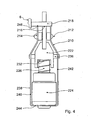
- FIG. 1 The figures of the drawing show a simplified representation of a rollover protection system 1 of a convertible vehicle, of which two arranged in the rear vehicle seats 26, 28 in Fig. 1 are indicated schematically.
- Each of the vehicle seats 26, 28 is associated with a rollover protection device 2 and 3, which each have a body-fixed first module 4 and a moved between a lowered rest position and an elevated support position second module 5 with a rollover body 6, wherein the second module 5 at a displacement movement is performed on the first module 4.
- the rollover body 6 is executed rod-like in all embodiments shown and has in its interior an axial receiving channel 8 for the spring energy storage 52.
- the spring energy accumulator 52 is shown in the figures partially only symbolically and can be carried out in a conventional manner as a helical compression spring.
- the rollover body 6 is in each case a straight rod body, although in other embodiments, where appropriate, a curvature can be provided in its upper region.
- the cross section of the rollover body 6 is in each case substantially round, wherein the inner cross-sectional contour in the embodiment according to Fig. 1 and Fig. 2 circular and in the execution after Fig. 8 is oval.
- the round core cross section surrounding flats 7 and webs 10, 11 and 12, 13 and 14, 15 are formed, wherein the flattening 7 and the webs 11 to 15 serve not only the stiffening, but also a rotation of the rollover body 6 and Part of the respective locking device 500, 600 of the rollover body 6 are.
- Fig. 1 In the execution according to Fig. 1 is the only principle indicated, serving as spring energy storage compression spring 52 is not visible in the receiving channel 8 of the rollover body 6 and surrounded by a locking pin 54 which with a as Guide device serving pipe profile 30 of the vehicle-fixed first module 4 is connected, secured.
- the receiving channel for the spring energy store in the rollover body 6 could extend only over a shorter longitudinal section of the rollover body and the spring force accumulator be supported on a foot portion 34 of the vehicle-fixed first module 4, as for example in the in Fig. 8 the embodiment shown is the case. It can therefore also in the execution after Fig. 1 be provided with a desired additional support of the spring pressure accumulator whose extension up to the foot portion 34 of the first module 4, wherein the spring pressure accumulator may optionally be arranged around a guide rod or on a rod.
- Fig. 1 and Fig. 8 is the serving as a guide device of the rollover body 6 pipe profile 30 with its lower edge opposite the foot member 34 of the first module 4 spaced, wherein the tube profile 30 in rest position of the rollover body 6, which in Fig. 1 is shown on the rollover protection device 2 shown on the right, an upper end region of the rollover body 6 surrounds and in supporting position of the rollover body 6, which in Fig. 1 Is shown on the left of the rollover protection device 3, the lower end portion of the rollover body 6 receives.
- connection of the tubular profile 30 with the foot member 34 of the body-mounted module 4 takes place in the embodiments shown in each case via a connecting profile 38, which on the side facing the vehicle side of the pipe profile 30 in a correspondingly shaped profile section 30 is inserted and screwed hereby.
- the connecting profile 38 is designed like the other profiles of the rollover protection system 1 as an extruded profile, wherein in the present case for the connection profile 38, a U-section is selected.
- any other profile shape of an open or closed profile for the connection profile can be chosen according to the present application, wherein the choice of geometry with regard to a slender construction of the rollover protection device 2 or 3 is to make.
- Fig. 1 the through-opening 60 is shown only schematically and can be adapted in terms of their size and geometry to the prevailing conditions.
- the rollover protection devices 2, 3 are each connected to a non-illustrated, executed in a conventional manner crash sensors of the vehicle, whereby the holding device 210, 310 or 410 is driven by means of the rollover body 6 against the force of the spring force memory 52 is kept at rest.
- the respective holding device 210, 310, 410 releases the rollover body 6, so that the rollover body 6 is displaced by the force of the spring force accumulator 52 in its extended upper support position in which he by the locking device 500 and 600 against a re-entry is saved.
- a baffle profile 16 with an opposite of the cross-sectional area of the rollover body 6 enlarged baffle 17.
- This impact profile which prevents a boring of the rod-like rollover body in the respective given surface in a vehicle rollover, is present, in particular in Fig. 8a is shown formed as a hollow profile with a plurality of cavities, which has a curvature on its surface facing away from the body floor or baffle surface. On the sides of the impact profile 19 is closed with panels 20.
- Fig. 4 . Fig. 5 , and Fig. 6 show in an enlarged scale that in the embodiment according to Fig. 1 used holding device 210 for holding the rollover body 6 of the rollover protection device. 3
- the holding device 210 comprises a locking element 214, which is mounted so as to be pivotable about a fixed axis of rotation 212 and has a pawl section 216 at its circumference, which is designed as a U-recess in the embodiment shown and for interacting with a locking element counter-body 218 is designed on the rollover body 6.
- the locking element counter body 218 is formed in the embodiment shown in a simple manner as the bolt, which also serves as a height stop for the rollover body 6.
- the dimensioning and shaping of the bolt 218 and the U-recess of the pawl portion 216 is coordinated so that the bolt 218 can easily slide out of the pawl portion 216 upon rotation of the locking member 214 about its axis of rotation 212.
- a retaining tab below a recess on the rollover body a shoulder on the rollover body or a suitable hook element may be provided as a locking element counter twill.
- the locking element 214 is secured by a locking member 222, which cooperates with an actuator 224, against a holding device 210 releasing rotation.
- the locking member 222 is presently designed as a on a cylindrical, by the actuator 224 axially movable piston fixed, flat, tongue-like sheet metal element.
- the locking member 222 engages in a peripheral recess 228 of the disc-like locking element 214, whereby the recess 228 forms a locking catch, which present in the rest position of the rollover body 6 coaxial with a longitudinal axis of the locking member 222 and the direction of action of the actuator 224, which corresponds to the direction of movement of the rollover body 6, is aligned and extending in the direction of an axis of rotation 212 of the locking element 214 forming, eccentrically arranged bolt 230 substantially perpendicular to the orientation of the U-shaped recess of the pawl portion 216.
- the actuator 224 is actuated by an associated control unit in an accident situation detected by a safety sensor of the convertible vehicle, the actuator 224 experiencing a change in state in the event of a crash, which translates the blocking member 222 in a direction opposite to the force of a compression spring 232 in the direction of the actuator 224 results.
- the blocking member 222 is pulled out by this translational movement in the direction of the actuator 224 from the peripheral recess 228 on the disc-like locking element 214 to a predefined, for example as a stop point, which this in consequence of the force exerted on the pin 218 of the rollover body 6 traction Performs rotational movement.
- a stop 234 is formed on the circumference of the disk-like locking element 214, on which the locking member 222 retracted when the holding device is released from the recess 228 comes into abutment upon rotation of the locking element 214 bringing the catch portion 216 out of engagement with the bolt 218.
- a pivoting of the locking element 214 about the rotation axis 212 by about 30 ° to trigger the holding device 210 is sufficient. Consequently, the circumferential contour of the locking element 214 in a range of approximately 30 ° in a region subsequent to the circumferential recess 228 counter to the release direction of rotation of the locking element 214 is radially retracted to the peripheral stop 234rd
- the stop 234 which holds the disc-like locking element 214 in cooperation with the locking member 222 in position after triggering the holding device 210, facilitates easy reversal of the rollover protection system in the event of a false triggering.
- the reversing takes place in a simple manner by a rotation of the locking element 214 in a blocking sense, until the pawl portion 216 again comes into engagement with the pin 218 of the rolled back into its rest position rollover body 6.
- the peripheral recess 228 is aligned with the locking member 222 which engages under the pressure of the compression spring 232 in the circumferential recess 228 and secures the locking member 214 against rotation.
- the locking element 214 is a two-stage disk, in which the arrangement and dimensioning of the recess 228 and the stopper 234 are to be selected depending on the arrangement and design of the actuator 224 and the locking member 222.
- the stop for the locking member 222 is formed on the locking element as a projection on the peripheral contour of the locking element, wherein the stop as a separate, to the locking element fixed component can be executed.
- the intended rotation angle of the locking element between the locked and unlocked position and the configuration of the actuator which may be, for example, a pin instead of the flat sheet metal element shown, the respective application selected accordingly.
- an abutment 236 is provided in the form of a bolt which serves to receive forces which in the released state of the holding means 210 on the part of the locking member 214 and the stop 234 on the locking member 222nd be exerted laterally. With the help of the abutment 236 tilting of the locking member 222 in the released state of the holding device 210 can be avoided even with a very long version of the locking member 222.
- the abutment 236, like the pivot axis 212 forming the bolt 230 is mounted on a housing element representing a base body 238 of the holding device 210, wherein the main body 238 opposite sides 240, 242, between which the bolt 230 and the abutment 236 are mounted.
- the base body 238 has in this case at its upper end in the installed state, ie at the free ends of the sides 240, 242, respectively, a ramp-like guide 246 for secure feeding of the Rolling body 6 and its retaining tab 218 in the engagement region with the pawl portion 216 of the locking element 214 on.
- a cross member 244 which is used in the present case as the seat of the actuator 224.
- the basic body 238 shown thus forms a kind of system cage, which advantageously fulfills the tasks of a housing which is often quite elaborate in the case of known designs with a considerably simpler design.
- the actuator 224 is in the embodiment after Fig. 4 .
- Fig. 5 , and Fig. 6 designed as an electromagnetic actuator of conventional design, but are also working on another principle operating actuators such.
- piezoelectric actuators pyrotechnic actuators or equipped with a fuse insert actuators, for use in the holding device 210th
- the rollover body 6 is automatically locked by the locking device 500 or 600, wherein the locking device 500 according to the in FIG Fig. 1 to Fig. 3 and Fig. 7 shown embodiment, at least one first latching device 505, which is formed with a U-shaped pawl 508.
- the pawl 508, which in Fig. 7 shown in isolation, has in the region of its U-traverse a tooth profile 507 with tapered teeth whose geometry is chosen so that they engage in supporting position of the rollover body 6 in a locking bar 509 a second, formed on the rollover body 6 locking device 506.
- the pawl 508 is supported on the tube profile 30 by being inserted into a circumferential recess 31 on the tube profile 30, which has the circumferential contour of the pawl 508 substantially.
- the pawl 508 is held in the axial direction of movement Z of the rollover body 6 form-fitting manner on the tube profile 30.
- the pawl 508 is spring-mounted by means of a leaf spring 510.
- the leaf spring 510 is initially arranged in the mounting position shown here in the longitudinal direction of the pawl 508. With this position of the leaf spring 510, the pawl 508 can be inserted into the recess 31, for example made by milling, on the tube profile 30. By rotating the leaf spring 510 by 90 ° in its functional position, this is introduced with its axial ends in formed on the tube profile 30 receiving slots 33, whereby the pawl 508 by means of the leaf spring 510 is spring-mounted relative to the tube profile 30.
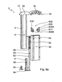
- the Fig. 8 shows a variant of the rollover protection device 3, which with an identical version of the corresponding rollover protection device 2 part of a in the FIGS. 20 to 22 shown assembly, but also for the in Fig. 1 shown assembly is suitable. Details of the rollover protection device 3 of Fig. 8 are more evident in the exploded view of Fig. 8a shown.
- the execution of the rollover protection device 2 or 3 according to Fig. 8 differs from the design according to Fig. 1 to Fig. 7 essentially by an alternative holding device 310 for the rollover body 6 and an alternative locking device 600 for supporting the rollover body 6 in its extended position and a modified drive system 50.
- an alternative holding device 310 for the rollover body 6 and an alternative locking device 600 for supporting the rollover body 6 in its extended position and a modified drive system 50.
- its profile design corresponds to the rollover body 6, which here has a substantially oval cross-sectional shape, basically the embodiment according to Fig. 1 to Fig. 7 ,
- the spring force accumulator 52 is formed here as a tension spring which is guided in the receiving channel 8 of the rollover body 6 on a spring guide rod 53.
- a spring suspension 55 is formed at its upper end and a spring plate 56 is slidably mounted on a central region, wherein the tension spring 52 between the spring suspension 55 and abutting against a stop of the rollover body 6 spring plate 56 in the rest position of the rollover body 6 Train is biased.
- FIG. 9 to FIG. 12 show in a simplified representation each equipped with a fuse link 348 holding device 310 for holding the rollover body 6 of the rollover protection device. 3
- the holding device 310 comprises a locking element 314, which is mounted pivotably about a fixed axis of rotation 312 and has a pawl section 316 on its circumference, which in turn is formed as a U-cutout in the embodiments shown and designed to interact with a locking element counter-body 318 on the rollover body 6 is.
- the locking element counter body could also here in a simple manner as a retaining tab below a recess on the rollover body 6 or as a bolt, a shoulder on the rollover body, or a suitable hook element may be formed.
- the locking element counter body 318 is formed as a shoulder in the region of a recess 320 open towards the lower edge of the rollover body 6 on the rollover body 6, wherein the recess 320, the shoulder 318 and the pawl portion 316 of the locking element 314 are designed to be coordinated with each other in that the locking element 314 can easily be brought out of engagement with the pawl section 316 during a rotation about its axis of rotation 312.
- the rollover body 6 is held in its lowered rest position by the engagement of the locking element 314 with the locking element counter body 318, and can be triggered by actuation of an actuator 324 by the actuator 324 at least partially rotation of the locking element 314 allows, so this out of engagement with the locking element counter body 318 device.
- the locking element 314 is held in its rest position locking the rollover body 6 by a melt insert 348 of the actuator 324 which can be melted in the event of a crash, wherein the locking element 314 is connected to a base body 338 in the rest position radially and loaded with tension via the fusible insert 348.
- the locking element 314 is formed in this embodiment lever-like manner as a kind of pivot lever.
- a lever end 315 a latch portion 316 for engagement with the locking element counter body 318 and the other end of the lever 317 a holder 360 for the connected to a power supply device 366 fuse link 348 on.
- the main body 338 is a block element with a substantially L-shaped cross section, wherein an L-leg 339 has a holder 361 for the fuse insert 348 with a Energyzu slaughter Republic Republic Korea Republic of China, and the other L-leg 341 has a bearing 374 of the pivotable locking member 314 with its bearing pin 330 carries.
- the bearing 374 constitutes a bearing plate screwed in a manner secured against rotation with the L-leg 341 of the base body 338, which is screwed on one side of the base body 338 and is curved S-shaped against the bearing of the bolt 330 of the locking element 314, so that the Locking element 314, the bearing plate 374 and the bearing pin 330 in the axial direction of the bearing pin 330 have an extension which substantially corresponds to the depth of this assembly axially overlapping body 338.
- the holding device 310 advantageously has a very small overall depth.
- the locking element 314 is aligned in the in the FIG. 9 to FIG. 12 shown embodiment with a side wall 302 of the here designed essentially as a box profile, a cassette performing rollover body 2 and engages as it laterally in a recess open to the bottom edge 320 of the z. B. biased by spring force rollover body 2, wherein the locking element 314 engages behind a formed on the contour of the recess 320, nose-like shoulder 318 which forms the locking element counter body.
- the person skilled in the art can also choose an arrangement of the holding device 310 on a narrow side 303 of the rollover body 6 or an engagement in a recess with a holding lug.
- the brackets 360, 361 for the fuse link 348 are also formed here as grooves into which the present plate-shaped fuse link 348 is firmly locked inserted.
- the fuse link 348 may have a cross-sectional constriction for locking a shape adapted to the grooves holding it and for faster fusing in its middle region.
- the energy supply device 367 for generating the heat necessary for melting the fuse link 348 is expediently embodied by means of terminals 365, 367 connected to a current source and attached to the ends of the fuse link 348.
- the material of the fuse element can represent any material known for fuses made of metal and / or plastic.
- the reversal of the rollover protection system with a return of the extended rollover body 6 in its lowered rest position can in the embodiment according to FIG. 9 to FIG. 12 be carried out in a simple manner by lowering the rollover body 6 in its rest position, wherein the rollover body 6 initially on a particularly clear in Fig. 11 apparent, on the upper edge of the rollover body 2 facing Lever end 315 formed, extending in the axial direction of the bearing pin 330 of the locking element 314 slope 319 of the locking element 314 meets.
- the locking element 314 is at least partially formed so flexible that the downwardly moving rollover body 6 when sliding along the slope 319 with the shoulder 318, the locking element 314 in the direction of in Fig. 11 apparent arrow 375 deflects or bends away until the pawl portion 316 snaps into the recess 320 of the rollover body 6 and holds it.
- FIGS. 13 to 16 show a simplified representation of another embodiment of a holding device 410 for holding the rollover body 6, which in terms of the locking element in the FIG. 9 to FIG. 12 corresponds embodiment shown, however, is pyrotechnic driven and, alternatively, in the in the FIG. 9 to FIG. 12 shown holding device 310 may be used.
- the holding device 410 also comprises a locking element 414 pivotally mounted about a fixed axis of rotation 412, which essentially acts like the locking element 314 of FIG. 9 to FIG. 12 shown retaining means 310 is formed at its periphery with a pawl portion 416 and which cooperates with a locking element counter body 418 on the rollover body 6.
- the locking element counter body 418 is formed in this embodiment as a paragraph in the region of a lower edge of the rollover body 6 below an open recess 420 on the rollover body 6.
- the locking element 414 has a in Fig. 13 shown in rest position, in which the locking element 414 is in engagement with the locking element counter body 418, in an in Fig. 14 and Fig. 15 shown pivoted position are transferred, in which the locking element 414 releases the rollover body 6.
- the locking member 414 is formed in the manner of a pivoting lever, wherein a lever end 415 the latch portion 416 for engagement with the locking element counter-body representing paragraph 418 of the rollover body 6 and the other end of the lever 417 abuts a stop member 428, which is an abutment for the side the rollover body 6 forms force on the locking element 414 and prevents rotation of the locking element 414.
- a bearing plate 474 screwed to the foot element 34 of the rollover protection device is provided, which rests on one side of the foot element 34 and is guided by a tab 440 therein and at its other end a bearing pin 430 carries for the pivotable locking element 414.
- the bearing plate 474 is curved S-shaped against the bearing of the bolt 430, whereby the locking element 414, the bearing plate 474 and the bearing pin 430 in the axial direction of the bearing pin 430 have an overlap and thus require only a small overall depth.
- the actuator 424 which causes a pivoting of the locking element 414, in this case has a pyrotechnic propellant 425.
- the pyrotechnic propellant 425 is in the embodiment shown on the stop element 428th and the bearing plate 474 opposite side of the foot member 34 is arranged such that its effective direction is substantially perpendicular to the pivoting direction of the locking element 414.
- Fig. 15 drives the pyrotechnic propellant 425 a foot element 34 by cross-bolt 426, which is arranged such that in the resting state of the locking member 414 abuts this.
- the bolt 426 In an electrical contacting of the pyrotechnic propellant 425 by means of an igniter 427 in a crash signal, the bolt 426 is moved by the pyrotechnic propellant 425 so far in the direction of the lower end of the lever 417 of the locking member 414, that the locking member 414 with its lower end 417 on the stop element 428 is lifted. Due to the force applied to the rollover body 6 in the extension direction, the locking element 414 is then pivoted, wherein it slides on a wedge surface 429 of the stop element 428 in the direction of the foot element 34.
- the reversing of the holding device 410 for holding the rollover body 6 displaced back again in its rest position can take place in that when the bolt 426 of the pyrotechnic propellant charge 425 is displaced backward, the locking element 414 is pivoted backwards, the rollover body 6 moving towards its rest position at the upper edge of the upper end of the lever 415 of the locking member 414 formed in the axial direction of the bearing pin 430 extending slope 419 of the locking member 414 strikes.
- a certain flexibility of the locking element 414 allows for a sliding of the rollover body 6 along the slope 419 with the shoulder 418, a deflection of the locking member 414 in the axial direction its bearing pin 430 until the pawl portion 416 engages in the recess 420 of the rollover body 6.
- Fig. 17 to Fig. 19 show closer in the execution of the rollover protection device according to Fig. 8 used locking device 600 for automatically locking the extended rollover body 6 in its supporting position.
- the locking device 600 has at least one first latching device 605 fixedly connected to the first module 4, which can be brought into operative connection with a second latching device 606 fixedly connected to the second module 5 for supporting the second module 5 and which has one movement of the second module 5, starting from its rest position in the direction of its supporting position.
- the first latching device 605 of the latching device 600 comprises in the in Fig. 8 illustrated embodiment, two in the direction of their operative position acted upon by a force, body-mounted rotatably mounted and each with a tooth profile 607 designed locking body 608A, 608B.
- Each blocking body 608A, 608B is assigned in each case a spring device 609, 610 via which the blocking bodies 608A, 608B are each sprung in the direction of the operative position of the first latching device 605 in such a manner that the blocking bodies 608A, 608B are pivoted about bearing bolts of the type shown in FIG Fig. 17 shown position in each case by a by an arrow X in Fig. 17 shown direction of rotation to be pivoted.
- the bearing bolts 611 are supported on the module 4 which is fixed to the body, wherein the locking bodies 608 A and 608 B act via the spring devices 609 and 610 in the form of bow-shaped wire springs Fig. 17 and Fig. 18 more detailed type and manner fixed in the axial extension of the bearing pin 611 and thus are clearly positioned.
- the spring devices 609 and 610 engage around the bearing bolts 611 on both sides of the disk-like locking bodies 608A and 608B.
- the spring means 609 and 610 are biased in the wrap region of the bearing pins 611 in the installation position to adjust the frictional force between the spring means 609 and 610 and the bearing pin 611 to such a value that the locking bodies 608A and 608B are not slidable on the bearing pin 611.
- the second latching device 606 is provided by a respective surface 606B of the second module 5 which can be moved to a blocking body 608A or 608B and which can be moved relative to the respectively corresponding blocking body 608A or 608B. or rollover body 6 is formed, with each of which the tooth profile 607 of a locking body 608A or 608B in operative position of the first latching device 605 is in frictional engagement such that a movement of the second module 5 is prevented from a position deviating from the rest position in the direction of its rest position.
- the spring devices 609 and 610 respectively associated with the blocking bodies 608A and 608B are each formed with blocking devices 609A, 610A, wherein the blocking bodies can be held in a position equivalent to a deactivated state of the first locking device 605 when the blocking device 610A is activated.
- the bow wire springs 609 and 610 are each provided with a first bow portion 610B, which is used to activate the locking means 610A with a second bow portion 610C in the in Fig. 18 is shown in such a manner engageable that the locking body 608A and 6 ⁇ 8B in the deactivated state of the first latching device 605 equivalent position in which a relative movement between the first module 4 and the second module 5 is not prevented by the locking device 600, being held.
- the stirrup wire springs 609 and 610 are each provided with a first leg 610D, which is substantially U-shaped, inserted into slot-like recesses 612 of the locking bodies 608A and 608B and abut with their second leg 610E on the module-fixed module 4 in such a way that the Spring means 609 and 610 are in a biasing position. Due to this bias, the blocking bodies 608A and 608B can be pivoted about the bearing pins 611 in the deactivated state of the locking devices 609A, 610A in their positions corresponding to the locking state of the first latching device 605.
- the first stirrup portions 610B of the stirrup wire springs each face the central portion, i. H. the U-traverse, the stirrup wire springs, which is inserted into the slot-like recess 612 of the locking body, subsequent areas in which the first leg 610D of the stirrup wire springs is designed with a larger width than the second stirrup areas 610C at congruent areas of the second, with two open straps trained thigh 610E.
- the legs 610D and 610E of the spring devices 609 and 610 thus form the locking devices 610A in such a way that, when the locking devices 610A are activated, they intersect in the region of the hoop areas 610B and 610C, hold each other and can not spread apart due to the internal prestressing, as shown in FIG Fig. 18 is apparent.
- the bow wire springs 609 and 610 are in the region of their free ends in the in Fig. 18 in a manner shown in more detail displaceably executed bow ends 610E_1 and 610E_2 executed. That is, the locking means 610A are each deactivatable or activatable by increasing the distance of the stirrup wire ends of the spring means 609 and 610 such that the leg arms of the spring means 609 and 610 can be brought past each other in the region of the stirrup portions 610B and 610C.
- the locking bodies 608A and 608B are then either in the non-locking position by the locking means 610A according to Fig. 18 and Fig. 19 held or for adjusting the operative position of the first latching device 605 according to the in Fig. 17 released position shown.
- the biasing force of the spring means 609 and 610 in the direction of the operative positions of the locking bodies 608A and 608B is presently provided such that engagement of the locking bodies 608A and 608B on the presently formed as a surface of the rollover body 6 locking means 606 does not hinder an extension movement.
- the locking elements 608A and 608B that represent the tooth-cam pivot about the bearing pin 611A counter to the direction of rotation X and thus do not build up a locking action between the two latching devices 605 and 606.
- the blocking body 608B When the blocking body 608B is pivoted into its operative position, the blocking body 608B, with its tooth profile 607 facing the latching surface 606B, at least partially penetrates into the latching surface 606B of the latching device 606, whereby there is a positive connection between the blocking body 608B and the rollover body 6 and the rollover body 6 is secure is held against a retraction in the direction of its rest position.
- the tooth geometry of the tooth profile 607 is executed with pointed, knife-like ends having teeth and the material for the tooth profile 607 against the material of the surface of the rollover body 6 harder to ensure a reliable locking of the rollover body 6.
- the rollover body 6 is formed on the underside of its impact profile 16 with wedge surfaces 18, in this case designed truncated pyramid unlocking elements 19, by means of which the locking bodies 608A, 608B are brought into the rest position in engagement with the second locking device 606 after a retraction of the rollover body.
- the blocking bodies 608A, 608B are withdrawn, with the widened bow portions 610B of the spring means 609 and 610 catching behind the free bow portions 610C and thus canceling out the effect of the bow wire springs 609, 610.
- the rollover body 6 can thus be lowered to its starting position.
- the free spring ends 610E_1, 610E_2 are pressed apart via the aforementioned unlocking elements 19 of the rollover body 6, so that the spring devices 609 and 610 bring the tooth cam or locking body 608A, 608B back against the latching surface 606B of the rollover body 6 ,
- the latching surfaces 606B in the present case are formed with a knurling or with a profile that increases the coefficient of friction of the latching surfaces.
- the locking bodies are each mounted on the body-first module, but also a reverse arrangement may be provided with a storage on the extendable module and a frictional engagement on a body-mounted surface.
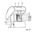
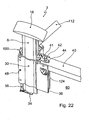
- FIGS. 20 to 22 a variant embodiment of the rollover protection system 1 is shown, in which not only the body-mounted and extendable modules 4, 5 of the rollover protection devices 2, 3 together with the holding device 210 or 310 or 410, the locking device 500 or 600 and the drive system 50 an outside form the vehicle functionally preassembled module, but in which a row of seats associated rollover protection devices 2, 3 total form a pre-assembled, fixable to the vehicle body assembly.
- the body-mounted modules 4 of the rollover protection devices 2, 3 are connected to each other by means of a cross member 40.
- the ends of the cross member 40 are each formed in the present embodiment with an undercut 41 having profile 42, which corresponds in terms of its shape with a profile 44 of the pipe section 30 of the body-first module 4.
- the cross member 40 thus forms a preassemblable unit of the rollover protection devices 2, 3, which can be screwed via lateral holes 48 with the vehicle body.
- the vehicle-mounted first module 4 of the respective rollover protection device 2, 3 each formed with an integrated remindhaltegurtsystem 100, wherein at mid-height of the tube profile 30, a belt retractor 110 per se known type in a rollover body 6 in the vehicle front direction upstream profile area 35 of the vehicle-fixed Tube profile 30 is inserted.
- the safety belt 112 is guided in the profiled area 35, which is designed as a hollow profile, to an upper safety belt guide or deflection 114.
- the seat belt 112 extends in the in Fig. 21 and Fig. 22 shown manner in the vehicle forward direction over a profile region 35 of the rollover protection device 2 and 3 upstream backrest of a vehicle seat and can be connected in a conventional manner with a seat belt buckle of a vehicle occupant.
- the illustrated restraint belt system 100 includes two upper anchoring points 120, 122 for a child seat belt, each one of the upper anchoring points 120, 122 being associated with a rollover protection device 2, 3, respectively.
- the upper anchoring point 120, 122 is in each case fastened to a profile wall 36, remote from the vehicle interior, of the first module 4, fixed to the body, or of the tubular profile 30, and has a tab 124, through which a belt fastened to a child seat can be pulled or hooked therein.
- the upper anchoring point 120 or 122 for a child seat which usually at two attachment points is fixed in the seat area, a third attachment point.
- the rollover protection devices 2, 3 each have a seat attachment device 150, which in the present case is each formed with an upper and a lower rear seat back fastening bolt 152 or 154.
- the rollover protection system 1 can thus constitute a multifunctional module which can connect the functionalities of a rollover protection device, a through-loading opening, a vehicle transverse reinforcement, a retaining belt seat and a seat attachment, wherein the entire multifunction module in its proposed compact design completes separately outside the vehicle and into a vehicle Final assembly can be used.
- the multifunction module is part of a convertible top of a convertible vehicle or that a convertible top linkage is connected to the component group having the rollover protection devices.
Abstract
Description
Die Erfindung betrifft ein Cabriolet-Fahrzeug mit einem Überrollschutzsystem nach der im Oberbegriff des Patentanspruches 1 näher definierten Art.The invention relates to a convertible vehicle with a rollover protection system according to the closer defined in the preamble of claim 1. Art.
Bei Personenkraftwagen, wie auch bei Traktoren, ist es bekannt, zur Schaffung eines Überlebensraumes für Insassen im Falle eines Fahrzeugüberschlags Überrollschutzsysteme bereitzustellen, welche einen Überrollkörper, wie z. B. einen Überrollbügel aufweisen, welcher einem einzelnen Fahrzeugsitz oder mehreren Fahrzeugsitzen zugeordnet ist und der in seiner Ruhelage in einer fahrzeugfesten Kassette verborgen ist, aus der er bei Erkennen einer Verunfallung des Fahrzeugs schlagartig in eine obere Stützlage verlagerbar und in dieser Stützlage verriegelbar ist.In passenger cars, as well as in tractors, it is known to provide for the creation of a survival space for occupants in the event of a vehicle rollover rollover protection systems, which a rollover body, such as. B. have a roll bar, which is associated with a single vehicle seat or more vehicle seats and is hidden in its rest position in a vehicle-mounted cassette, from which it is suddenly recognizable upon detection of an accident of the vehicle in an upper support position and lockable in this support position.
In der Praxis allgemein verwendete Überrollbügel bestehen typischerweise aus einem U-förmigen Bügel, dessen rohrförmige Schenkel in Standrohren eines fahrzeugfesten Moduls vertikal geführt sind. Im Inneren jedes Schenkels ist eine Spiralfeder angeordnet, welche durch eine Haltevorrichtung unter Vorspannung gehalten wird, die in Abhängigkeit eines Crash-Signals der Fahrzeugsensorik lösbar ist, wodurch der Überrollbügel unter der Wirkung der Feder in Zehntelsekunden ausgefahren und in seiner Stützlage durch eine geeignet Verriegelungsvorrichtung arretiert wird. Die beiden rohrförmigen Schenkel sind dabei durch ein Querjoch miteinander verbunden, über das meist ein gepolstertes Prallelement geschoben ist.In practice, generally used roll bars are typically made of a U-shaped bracket whose tubular legs are vertically guided in stanchions of a vehicle-fixed module. Inside each leg a coil spring is arranged, which is held by a holding device under bias, which is releasable in response to a crash signal of the vehicle sensor, whereby the roll bar under the action of the spring extended in tenths of a second and locked in its supporting position by a suitable locking device becomes. The two tubular legs are connected to each other by a transverse yoke over which a padded impact element is usually pushed.
In der
Problematisch ist bei solchen, die gesamte Fahrzeugbreite überspannenden Überrollbügeln mit einer Zwangsführung ihrer Schenkel auf der jeweiligen Fahrzeugseite, dass häufig ein so genannter Schubladeneffekt zu beobachten ist, worunter ein Verkanten oder Verklemmen des Überrollbügels bei dessen Aktivierung aufgrund von Fertigungstoleranzen oder mangelnder Synchronisation der an den Bügelschenkeln angreifenden Antriebe verstanden wird.The problem with such, the entire vehicle width spanning roll bars with forced guidance of their legs on the respective vehicle side that often a so-called drawer effect is observed, including tilting or jamming of the roll bar when it is activated due to manufacturing tolerances or lack of synchronization of the bracket legs attacking drives is understood.
Als Beispiel für eine nur einem Fahrzeugsitz zugeordnete Überrollschutz-Vorrichtung mit einem Überrollkörper, welcher unabhängig von einem einem anderen Fahrzeugsitz zugeordneten Überrollkörper ausfahrbar ist, wird exemplarisch auf die
Die Bereitstellung einer solchen Überrollschutz-Vorrichtung für jeden Fahrzeugsitz bedingt nachteilhafterweise eine hohe Bauteilanzahl und ein insgesamt hohes Gewicht für das gesamte Überrollschutzsystem.The provision of such a rollover protection device for each vehicle seat disadvantageously entails a high number of components and an overall high weight for the entire rollover protection system.
Die vorbeschriebenen Überrollschutzsysteme, wie auch aus der Praxis bekannte Überrollschutz-Vorrichtungen, weisen zudem den Nachteil auf, dass eine Durchlademöglichkeit zwischen den an die Überrollschutz-Vorrichtung angrenzenden Fahrzeugräumen aufgrund der beidseitigen Antriebe des Überrollbügels und dessen Führungseinrichtungen häufig nur sehr begrenzt ist. So erlauben die in der Regel mittig zu einem Fahrzeugsitz angeordneten Überrollschutz-Vorrichtungen keine oder nur klein dimensionierte Durchladen zwischen einem Insassenraum und einem fahrzeugheckseitigen Stauraum, da für die Durchlade nur der geringe Abstandsbereich zwischen den Überrollschutz-Vorrichtungen der jeweiligen Sitze zur Verfügung steht.The above-described rollover protection systems, as well as known from practice rollover protection devices, also have the disadvantage that a through-loading possibility between the adjacent to the rollover protection device vehicle spaces due to the two-sided drives the roll bar and its guide devices is often very limited. Thus, the rollover protection devices, which are generally arranged centrally to a vehicle seat, permit no or only small-sized through-loading between a passenger compartment and a vehicle rear-side storage space, since only the small clearance area between the rollover protection devices of the respective seats is available for the through-loading.
Noch begrenzter sind die Möglichkeiten zur Realisierung einer Durchlade bei Überrollschutz-Vorrichtungen, welche als eine vorgefertigte Baueinheit an einer karosseriefesten Aufnahme befestigt werden, beispielsweise an einer hinter Fahrzeugsitzen angeordneten Fahrzeugquerwand.Even more limited are the possibilities for the realization of a through-loading in rollover protection devices, which are attached as a prefabricated unit to a body-mounted receptacle, for example on a rear vehicle arranged vehicle transverse wall.
Eine solche hinsichtlich der Fertigung vorteilhafte Ausgestaltung einer Überrollschutz-Vorrichtung ist beispielsweise in der
Im Übrigen ist es aus der
Weiterhin ist es aus der
Es ist Aufgabe der vorliegenden Erfindung, ein Cabriolet-Fahrzeug mit einem Überrollschutzsystem der eingangs genannten Art zu schaffen, das sich durch eine hohe Funktionssicherheit im Crash-Fall sowie durch eine großzügige Durchlademöglichkeit auszeichnet.It is an object of the present invention to provide a convertible vehicle with a rollover protection system of the type mentioned, which is characterized by a high reliability in the event of a crash as well as a generous through-loading facility.
Diese Aufgabe wird mit einem ein Überrollschutzsystem aufweisenden Cabriolet gemäß den Merkmalen des Patentanspruches 1 gelöst.This object is achieved with a rollover protection system having Cabriolet according to the features of claim 1.
Es ist somit ein Cabriolet-Fahrzeug mit einem Überrollschutzsystem mit wenigstens einer einem Fahrzeugsitz zugeordneten Überrollschutzvorrichtung vorgesehen, welches jeweils ein karosseriefestes erstes Modul mit Führungseinrichtungen für ein zwischen einer abgesenkten Ruhelage und einer erhöhten Stützlage verfahrbares zweites Modul mit einem Überrollkörper, welcher eine Prallfläche zur Kontaktierung eines Untergrundes bei einem Fahrzeugüberschlag aufweist, aufweist, wobei eine lösbare Halteeinrichtung zum Halten des zweiten Moduls in seiner Ruhelage, eine Verriegelungsvorrichtung zum Abstützen des zweiten Moduls in einer von seiner Ruhelage abweichenden Position und ein Antriebssystem mit einem Federkraftspeicher, mittels dem das zweite Modul in seiner Ruheposition vorgespannt und im Bedarfsfall in Richtung seiner Stützlage verlagerbar ist, vorgesehen sind.It is thus a convertible vehicle with a rollover protection system provided with at least one vehicle seat associated rollover protection device, each having a body-first module with guide means for a moved between a lowered rest position and an elevated support position second module with a rollover body, which has a baffle for contacting a Background in a vehicle rollover having, wherein a releasable holding means for holding the second module in its rest position, a locking device for supporting the second module in a position deviating from its rest position and a drive system with a spring energy storage, by means of which the second module in its rest position biased and, if necessary, in the direction of its support position is displaced, are provided.
Erfindungsgemäß weisen die Überrollschutz-Vorrichtungen zweier Fahrzeugsitze einer Sitzreihe unmittelbar am oder im Fahrzeugsitz angeordnete Überrollkörper auf, die mit ihren zugehörigen Modulen jeweils in entgegengesetzter Richtung im Wesentlichen außermittig zu dem zugeordneten Fahrzeugsitz und eine Durchlademöglichkeit im Bereich einer Fahrzeugquerversteifung bildend beabstandet zueinander angeordnet sind.According to the invention, the rollover protection devices of two vehicle seats of a row of seats directly on or in the vehicle seat arranged rollover body, which are arranged with their respective modules in the opposite direction substantially off-center to the associated vehicle seat and a through-loading possibility in the region of Fahrzeugquerversteifung forming spaced from each other.
Eine außermittige Anordnung der Überrollschutz-Vorrichtungen, das heißt, dass deren Komponenten überwiegend im Bereich einer einer Fahrzeugseite zugewandten Seite des betreffenden Fahrzeugsitzes angeordnet sind, ermöglicht vorteilhafterweise die Anordnung einer großzügige Durchladeöffnung zwischen den Fahrzeugsitzen.An eccentric arrangement of the rollover protection devices, that is, their components predominantly in the region of a vehicle side facing side of the vehicle seat concerned are arranged advantageously allows the arrangement of a generous through-opening between the vehicle seats.
In einer vorteilhaften Ausgestaltung ist erfindungsgemäß bei einem solchen Überrollschutzsystem der Überrollkörper stangenartig ausgeführt, wobei er in seinem Inneren einen axialen Aufnahmekanal für den Federkraftspeicher aufweist. Dabei weist das erste Modul als Führungseinrichtungen des Überrollkörpers ein Rohrprofil auf, in dem in Ruhelage des Überrollkörpers wenigstens ein oberer Endbereich und in Stützlage ein unterer Endbereich des Überrollkörpers aufgenommen sind.In an advantageous embodiment according to the invention in such a rollover protection system, the rollover body is designed rod-like, wherein it has an axial receiving channel for the spring energy storage in its interior. In this case, the first module as a guide means of the rollover body on a tubular profile, in which in rest position of the rollover body at least one upper end portion and in supporting position, a lower end portion of the rollover body are added.
Das Cabriolet-Fahrzeug nach der Erfindung weist somit für jeden Fahrzeugsitz eine Überrollschutz-Vorrichtung auf, welche unabhängig von der Überrollschutz-Vorrichtung eines anderen Sitzes angetrieben wird, so dass eine Verkantung des ausfahrbaren Moduls bei dessen Ausfahrbewegung und somit eine Beeinträchtigung der Funktionssicherheit oder gegebenenfalls zusätzliche erforderliche Synchronisationseinrichtungen vermieden werden können.The convertible vehicle according to the invention thus has for each vehicle seat on a rollover protection device which is driven independently of the rollover protection device of another seat, so that a tilting of the extendable module in its extension movement and thus an impairment of the reliability or possibly additional required synchronization devices can be avoided.
Die stangenartige Ausgestaltung des Überrollkörpers mit einem axialen Aufnahmekanal für den Federkraftspeicher hat den Vorteil, dass der Federkraftspeicher, welcher zur Verlagerung des Überrollkörpers erforderlich ist, in den Überrollkörper integriert sein kann, wobei durch die Formgebung der Innenkontur des Überrollkörpers entsprechend der Form des Federdruckspeichers auf eine zusätzliche Federführung verzichtet werden kann.The rod-like configuration of the rollover body with an axial receiving channel for the spring energy storage has the advantage that the spring energy storage, which is required for the displacement of the rollover body, can be integrated into the rollover body, wherein the shape of the inner contour of the rollover body corresponding to the shape of the spring pressure accumulator on a additional spring guide can be omitted.
Der Federkraftspeicher kann dabei als eine Druckfeder ausgebildet sein, welche an dem karosseriefesten ersten Modul und dem Überrollkörper abgestützt ist. Abweichend hiervon kann jedoch auch eine Zugfeder vorgesehen sein, welche beispielsweise zwischen einer sich bis in das Innere des Überrollköpers koaxial hierzu erstreckenden Stange und dem durch die lösbare Halteeinrichtung gehaltenen Überrollkörper derart vorgespannt eingebaut ist, dass der Überrollkörper nach einer Freigabe durch die lösbare Halteeinrichtung auf Grund der Zugkraft der Feder in eine obere Stützlage überführt wird.The spring energy accumulator can be designed as a compression spring, which is supported on the body-mounted first module and the rollover body. Deviating from this can However, also be provided a tension spring, which, for example, between a coaxially extending into the interior of the Überrollköpers rod and the through detachable holding device held rollover body is installed biased such that the rollover body is transferred to a release by the releasable holding device due to the tensile force of the spring in an upper supporting position.
Bei einer Ausführung ohne jegliche Führungsstange kann eine solche Zugfeder auch an einem karosseriefesten Bolzen, welcher sich beispielsweise durch einen Längsschlitz in das Innere des Überrollbügels erstreckt, gehalten sein, so dass der Federkraftspeicher ohne weitere Führung vollständig durch den Überrollkörper geführt ist.In an embodiment without any guide rod, such a tension spring can also be held on a bolt which is fixed to the body, which extends, for example, through a longitudinal slot into the interior of the roll bar, so that the spring energy store is guided completely through the roll body without further guidance.
Eine vollständige Führung des Federkraftspeichers durch den Überrollkörper ist auch bei einer Druckfeder möglich, welche zwischen einem an dem Überrollkörper ausgebildeten Anschlag und einem sich durch eine Ausnehmung in den Überrollkörper erstreckenden karosseriefesten Anschlag, welcher beispielsweise als Bolzen mit einem Federteller ausgebildet sein kann, unter Druckspannung stehend eingebaut ist.A complete guidance of the spring force accumulator by the rollover body is also possible with a compression spring, which between a trained on the rollover body stop and a extending through a recess in the rollover body-mounted stop, which may be formed, for example, as a bolt with a spring plate, under compressive stress is installed.
Hiermit und indem das erste Modul als Führungseinrichtung des Überrollkörpers ein Rohrprofil aufweist, welches in Ruhelage des Überrollkörpers wenigstens dessen oberen Endbereich und in Stützlage dessen unteren Bereich aufnimmt, wird eine schlanke und kompakte Bauweise der jeweiligen Überrollschutz-Vorrichtung erzielt, welche ggf. zusammen mit der außermittigen Anordnung der Überrollschutz-Vorrichtungen beispielsweise hinter den Fondsitzen eine große Durchlademöglichkeit für sperrige Güter zwischen einem Fahrzeuginnenraum und einem heckseitigen Aufnahmeraum bietet.Hereby and by the first module as a guide device of the rollover body having a tubular profile which receives at rest the rollover body at least its upper end and in support the lower region, a slim and compact design of the respective rollover protection device is achieved, which together with the eccentric arrangement of the rollover protection devices, for example, behind the rear seats offers a great through-loading facility for bulky goods between a vehicle interior and a rear-side receiving space.
Zur weiteren Bauraum- und Gewichtsreduzierung kann bei einer vorteilhaften Ausführung der Erfindung vorgesehen sein, dass das eine Führungseinrichtung des Überrollkörpers bildende Rohrprofil mit seinem unteren Rand gegenüber einem Fußelement des ersten Moduls beabstandet angeordnet ist.For further space and weight reduction can be provided in an advantageous embodiment of the invention that the one guide means of the rollover body forming Tube profile is arranged with its lower edge opposite a foot element of the first module spaced.
Zur Verbindung des Rohrprofils mit dem Fußelement des ersten Moduls kann dabei ein seitlich des Rohrprofils befestigtes Verbindungsprofil, welches beispielsweise ein U-Profil oder ein Kastenprofil sein kann, vorgesehen sein.To connect the pipe profile with the foot member of the first module can be provided laterally of the pipe profile fastened connection profile, which may be, for example, a U-profile or a box section.
Die Führungseinrichtungen des fahrzeugfesten ersten Moduls können genauso wie die Bauelemente des ausfahrbaren Moduls, insbesondere der Überrollkörper, aus kostengünstigen Strangpressprofilen hergestellt sein.The guide means of the vehicle-mounted first module, as well as the components of the extendable module, in particular the rollover body, be made of inexpensive extruded profiles.
Dabei kann z. B. das als Führungseinrichtung dienende Rohrprofil in einfacher Weise mit weiteren Funktionselementen kombiniert werden, wie z. B. mit einer Rasteinrichtung der Verriegelungseinrichtung, welche an dem Rohrprofil abgestützt sein kann.It can be z. B. the serving as a guide device tube profile are combined in a simple manner with other functional elements, such. B. with a locking device of the locking device, which may be supported on the pipe profile.
Bei einer sehr kostengünstigen Ausführung kann das Rohrprofil z. B. eine umfangsseitige Ausnehmung zur Aufnahme der hieran abgestützten Rasteinrichtung der Verriegelungseinrichtung aufweisen, wobei die Rasteinrichtung in Bewegungsrichtung des Überrollkörpers formschlüssig an dem Rohrprofil gehalten ist und nicht weiter mit dem Rohrprofil verbunden ist.In a very cost-effective design, the pipe profile z. Example, have a peripheral recess for receiving the latching device supported thereon of the locking device, wherein the latching device is held in the direction of movement of the rollover body form-fitting manner on the tube profile and not further connected to the tube profile.
Die in Kompaktbauweise und außermittig hinter den Fahrzeugsitzen positionierbaren Überrollschutz-Vorrichtungen können in einer vorteilhaften Ausgestaltung funktionsfähig vormontierte Baugruppen bilden, die an dem Fahrzeugaufbau festlegbar sind.The rollover protection devices that can be positioned compactly and off-center behind the vehicle seats can, in an advantageous embodiment, form functionally preassembled subassemblies that can be fixed to the vehicle body.
Die so gebildete Bauteilgruppe aus erstem Modul, zweitem Modul, Halteeinrichtung, Verriegelungsvorrichtung und Antriebssystem kann in einem einzigen Montageschritt in die vorgesehene Fahrzeugkarosserie eingesetzt werden und muss dann nur noch an den Kabelbaum im Fahrzeug angeschlossen werden. Dabei können auch Auslösesensoren für die Überrollschutz-Vorrichtungen in die jeweilige Bauteilgruppe integriert sein.The thus formed component group of first module, second module, holding device, locking device and drive system can be used in a single assembly step in the proposed vehicle body and then only has to be connected to the wiring harness in the vehicle. In this case, trigger sensors for the rollover protection devices can be integrated into the respective component group.
Die Befestigung der Überrollschutz-Vorrichtungen an dem Fahrzeugaufbau kann beispielsweise mittels Verschraubung an einer vertikal stehenden Fahrzeugquerwand hinter den Sitzen erfolgen oder aber an Aufnahmen an der Fahrzeugseite, wenn die Bauteilgruppe mit dem erfindungsgemäßen Überrollschutzsystem gleichzeitig die Fahrzeugquerwand bildet.The attachment of the rollover protection devices on the vehicle body can be done for example by means of screwing on a vertical vehicle transverse wall behind the seats or on shots on the vehicle side, when the component group with the rollover protection system according to the invention simultaneously forms the vehicle transverse wall.
In einer einfachen Ausgestaltung kann die Versteifung in Fahrzeugquerrichtung durch einen einfachen, die Überrollschutz-Vorrichtungen oberhalb einer Durchladeöffnung verbindenden Querträger realisiert werden.In a simple embodiment, the stiffening in the vehicle transverse direction can be realized by a simple, the rollover protection devices connecting above a through-opening cross member.
Bei einer besonders kompakten Ausführung des erfindungsgemäßen Überrollschutzsystems kann in das erste, karosseriefeste Modul ein Rückhaltegurtsystem mit Sicherheitsgurtführungen für wenigstens einen Sicherheitsgurt integriert sein.In a particularly compact embodiment of the rollover protection system according to the invention, a restraining belt system with safety belt guides for at least one safety belt can be integrated into the first, body-mounted module.
Die Komponenten eines Sicherheitsgurtsystems, wie z. B. ein Gurtaufroller und eine obere Sicherheitsgurtführung, können über entsprechende Aufnahmen, welche ohne besonderen Aufwand bei der Herstellung der Profile des ersten Moduls vorgesehen werden können, problemlos in die fahrzeugfesten Bauteile des Überrollschutzsystems integriert werden.The components of a safety belt system, such. As a belt retractor and an upper seat belt guide, can be easily integrated into the vehicle-mounted components of the rollover protection system via appropriate images, which can be provided without any special effort in the production of the profiles of the first module.
Das Rückhaltegurtsystem kann dabei nicht nur Sicherheitsgurte zum Angurten von erwachsenen Personen umfassen, sondern auch Kindersitzhaltegurte, wobei bei einer besonders vorteilhaften Ausführung auch ein oberer Verankerungspunkt für einen Kindersitzhaltegurt, welcher auch als Toptether-Befestigung bezeichnet wird, an einem fahrzeugfesten Bauteil des Überrollschutzsystems angeordnet ist.The restraint belt system may include not only seatbelts for adult strapping, but also child seat straps, and in a particularly advantageous embodiment also an upper anchorage point for a child seat belt, which is also referred to as a top tether attachment, is arranged on a vehicle-mounted component of the rollover protection system.
Das erfindungsgemäße Überrollschutzsystem kann bei einer besonders vorteilhaften Ausführung zusammen mit den Überrollschutz-Vorrichtungen und gegebenenfalls einer Durchladeöffnung und einem fahrzeugversteifenden Querträger als vollständig vormontierte Baugruppe ausgebildet sein, so dass diese mulifunktionale Baugruppe als ein einziges vorkonfiguriertes Modul beim Fahrzeugbau in die Karosserie eingesetzt und hieran beispielsweise durch Schraubverbindungen befestigt werden kann.The rollover protection system according to the invention can be formed in a particularly advantageous embodiment together with the rollover protection devices and optionally a through-opening and a stiffening vehicle cross member as a completely pre-assembled assembly, so that this mulifunktionale module used as a single preconfigured module in vehicle bodywork in the body and this example, by Screw connections can be attached.
Eine solche separat komplettierte Baugruppe, die bei der Endmontage in das Fahrzeug eingesetzt wird, kann zusätzlich auch Sitzkomponenten, wie z. B. ein oberes und unteres Sitzlehnenlager, umfassen.Such a separately completed assembly that is used in the final assembly in the vehicle, in addition, seat components such. As an upper and lower seatback storage include.
Die lösbare Halteeinrichtung zum Halten des zweiten Moduls mit dem Überrollkörper in seiner Ruheposition kann bei einer vorteilhaften Ausführung ein um eine feste Drehachse schwenkbar gelagertes Verriegelungselement umfassen, welches scheibenartig ausgebildet ist und welches neben einem Klinkenabschnitt eine umfangsseitige Ausnehmung, in die ein Sperrglied eines Aktuators in Ruheposition eingreift, und einen umfangsseitigen Anschlag, an dem das zur Überführung des zweiten Moduls in dessen Stützposition durch den Aktuator aus der Ausnehmung zurückgenommene Sperrglied nach einer den Klinkenabschnitt aus Eingriff mit dem Verriegelungs-Gegenkörper bringenden Rotation des Verriegelungselementes anliegt, aufweist.The releasable holding device for holding the second module with the rollover body in its rest position may comprise in an advantageous embodiment a pivotally mounted about a fixed axis locking element, which is disc-like and which next to a pawl portion a peripheral recess into which a locking member of an actuator in rest position engages, and a peripheral stop on which the transfer of the second module in its supporting position by the actuator from the recess withdrawn locking member abuts the latch portion from engagement with the locking counter-body rotating rotation of the locking element has.
Eine solche Ausgestaltung der lösbaren Halteeinrichtung und der hiermit ausgestatteten Überrollschutz-Vorrichtung ermöglicht eine sichere und kostengünstige Verriegelung des Überrollkörpers in seiner Ruheposition, wobei die Halteeinrichtung vorteilhafterweise mit wenigen ohne großen Präzisionsaufwand zu fertigenden Bauteilen realisiert werden kann. Das scheibenartige Verriegelungselement ersetzt dabei die Hebel eines bekannten Doppelhebelsystems und kann ohne Federeinrichtung gegenüber dem Sperrglied des Aktuators gelagert werden.Such an embodiment of the releasable holding device and the rollover protection device equipped therewith makes possible a secure and cost-effective locking of the rollover body in its rest position, wherein the holding device can advantageously be realized with a few components without great precision to be produced. The disc-like locking element replaces the lever of a known double lever system and can be stored without spring device against the locking member of the actuator.
In einfacher Ausgestaltung kann es vorgesehen sein, dass das Sperrglied durch den Aktuator in Axialrichtung linear bewegbar ist, womit eine Ausgestaltung des Aktuators z. B. als elektromagnetischer oder piezoelektrischer Aktuator, welcher das Sperrglied in dessen Axialrichtung zur Auslösung des Überrollkörpers zurückzieht, möglich ist. Das Sperrglied kann dabei ein mittels einer Feder entgegen dem Verriegelungselement vorgespannter Stift oder ein Blechelement einfacher Bauart sein.In a simple embodiment, it may be provided that the locking member is linearly movable by the actuator in the axial direction, whereby an embodiment of the actuator z. As an electromagnetic or piezoelectric actuator, which retracts the locking member in the axial direction for triggering the rollover body, is possible. The locking member may be a biased by a spring against the locking element pin or a sheet metal element simple design.
In einer vorteilhaften Ausgestaltung der Erfindung wird die Drehachse des Verriegelungselements durch einen Bolzen gebildet, welcher an gegenüberliegenden Seiten eines Grundkörpers gelagert ist, wobei die Seiten des Grundkörpers durch eine Traverse miteinander verbunden sind, welche einen Sitz für den Aktuator bildet. Der Grundkörper stellt somit eine Art Käfig für die lösbare Halteeinrichtung dar, mit dem die Halteeinrichtung an beliebigen karosseriefesten Bauelementen des Überrollschutzsystems angeordnet werden kann.In an advantageous embodiment of the invention, the axis of rotation of the locking element is formed by a bolt which is mounted on opposite sides of a base body, wherein the sides of the base body are interconnected by a cross member, which forms a seat for the actuator. The main body thus represents a kind of cage for the releasable holding device with which the holding device can be arranged on any body-mounted components of the rollover protection system.
In einer besonders einfachen Ausgestaltung kann der Grundkörper im Wesentlichen als ein U-Profil ausgebildet sein, wobei die Seitenschenkel des U-Profils die Seiten des Grundkörpers bilden.In a particularly simple embodiment, the main body may be formed substantially as a U-profile, wherein the side legs of the U-profile form the sides of the body.
Eine weitere vorteilhafte Ausführung des erfindungsgemäßen Überrollschutzsystems sieht vor, dass das schwenkbare Verriegelungselement, welches mit einem Verriegelungselement-Gegenkörper des zweiten Moduls in Ruheposition des Überrollkörpers in Eingriff steht und im Crash-Fall den Überrollkörper zur Überführung in dessen Stützposition freigibt, in Ruheposition durch einen im Crash-Fall aufschmelzbaren Schmelzeinsatz des Aktuators gehalten ist.A further advantageous embodiment of the rollover protection system according to the invention provides that the pivotable locking element, which engages with a locking element counter-body of the second module in the rest position of the rollover body and releases the rollover body in the support position in the event of a crash, in the rest position by a in Crash case fusible melt insert of the actuator is held.
Die Verwendung eines Schmelzeinsatzes zum Halten des Verriegelungselementes und zum Aufheben der Verriegelungsstellung im Crash-Fall gewährleistet auf einfache und kostengünstige Art und Weise eine zuverlässige und schnelle Auslösung des Überrollkörpers.The use of a fuse link to hold the locking element and to cancel the locking position in the event of a crash ensures a reliable and quick release of the rollover body in a simple and cost-effective manner.
Wenn nur das schwenkbar gelagerte und in Ruheposition des Überrollkörpers in Eingriff mit dem Verriegelungselement-Gegenkörper stehende Verriegelungselement durch den Schmelzeinsatz gehalten werden muss, kann der Schmelzeinsatz auf wesentlich niedrigere Kräfte ausgelegt sein, als er zum direkten Halten des zweiten Moduls bzw. des Überrollkörpers ausgelegt sein müsste. Die entsprechend reduzierte Dimensionierung des Schmelzeinsatzes ermöglicht wiederum ein schnelles Aufschmelzen und damit Durchtrennen der hiermit verbundenen Bauteile, womit die Auslösung des Überrollkörpers in sehr kurzer Zeit erfolgen kann.If only the pivotally mounted and standing in the rest position of the rollover body in engagement with the locking element counter body locking element must be held by the fuse link, the fuse link can be designed for much lower forces than it is designed for direct holding of the second module or the rollover body would. The correspondingly reduced dimensioning of the fuse insert in turn allows a rapid melting and thus cutting through the components connected thereto, whereby the triggering of the rollover body can be done in a very short time.
Der Schmelzeinsatz kann prinzipiell eine beliebige Form haben und z. B. plattenförmig oder stab- bzw. drahtförmig ausgebildet sein.The melting insert can in principle have any shape and z. B. plate-shaped or rod or wire-shaped.
Auch das schwenkbare Verriegelungselement kann bei der Halteeinrichtung des erfindungsgemäßen Überrollschutzsystems grundsätzlich in beliebiger Form ausgestaltet sein.Also, the pivotable locking element can be configured in principle in any form in the holding device of the rollover protection system according to the invention.
In einer vorteilhaften Ausgestaltung der Erfindung kann zwischen dem Verriegelungselement und dem Aktuator ein Sperrglied angeordnet sein, welches das Verriegelungselement in einer den Überrollkörper haltenden Sperrstellung hält oder freigibt. Dabei kann es vorgesehen sein, dass das Sperrglied in Sperrstellung gegen einen Sitz, welcher durch den aufschmelzbaren Schmelzeinsatz des Aktuators gehalten ist, mittels eines Energiespeichers vorgespannt ist. Bei einem erkannten Crash kann der Sitz des Sperrglieds durch ein Aufschmelzen des Schmelzeinsatzes z. B. durch Anlegen einer speziell abgestimmten Stromspannung blitzartig aufgehoben werden, so dass das vorgespannte Sperrglied in Richtung des aufgehobenen Sitzes entweichen und das Verriegelungselement freigeben kann. Der Energiespeicher kann als eine Feder ausgebildet sein, welche einenends an einem an dem Sperrglied ausgebildeten Federsitz und anderenends an einem gehäuseartigen Grundkörper abgestützt ist.In an advantageous embodiment of the invention may be arranged between the locking element and the actuator, a locking member which holds the locking element in a locking body holding the locking position or releases. It can be provided that the locking member is biased in the locked position against a seat which is held by the fusible melt insert of the actuator by means of an energy storage device. In a detected crash, the seat of the locking member by melting the fuse link z. B. be lifted in a flash by applying a specially tuned voltage, so that the biased locking member escape in the direction of the lifted seat and can release the locking element. The energy storage device may be formed as a spring, which is supported at one end on a spring seat formed on the locking member and the other end on a housing-like base body.
Um ein Herausfallen des Sperrglieds nach Aufheben des zuvor durch den Schmelzeinsatz gesicherten Sitzes bei einer Entspannung der Feder des Sperrglieds zu vermeiden und um die Reversierbarkeit einer Auslösung der Halteeinrichtung zu erleichtern, kann an dem Grundkörper ein Sperrgliedanschlag zur Begrenzung des Weges des Sperrglieds nach einem Lösen des Sitzes im Crash-Fall in einer dem Verriegelungselement abgewandten Richtung vorgesehen sein.To avoid falling out of the locking member after canceling the previously secured by the fuse seat with a relaxation of the spring of the locking member and to facilitate reversibility of a release of the holding device, on the main body a locking member stop for limiting the path of the locking member after a release of the Seat in the event of a crash may be provided in a direction remote from the locking element.
Der Sitz des Sperrglieds in Sperrstellung kann durch wenigstens zwei schwenkbar gelagerte Backenkörper gebildet sein, welche durch den Schmelzeinsatz miteinander verbunden sind. Die Verbindung zwischen den Backenkörpern wird somit im Crash-Fall aufgehoben, so dass diese durch die Krafteinwirkung des Sperrglieds auseinander geschwenkt werden können.The seat of the locking member in the blocking position may be formed by at least two pivotally mounted jaw body, which are interconnected by the fuse link. The connection between the jaw members is thus canceled in the event of a crash, so that they can be pivoted apart by the force of the locking member.
Eine solche Ausgestaltung mit einem Sperrglied ist in der deutschen Patentanmeldung (Aktenzeichen der Anmelderin: Kk/P-01037/01039 DE, gleicher Anmeldetag) näher beschrieben.Such a configuration with a locking member is described in more detail in the German patent application (file number of the applicant: Kk / P-01037/01039 DE, same filing date).
Bei einer Ausführung ohne separates Sperrglied kann das Verriegelungselement gegebenenfalls direkt gegen einen Sitz, welcher durch einen aufschmelzbaren Schmelzeinsatz in Ruhelage des Systems gehalten ist, gedrückt sein. Wenn an dem Verriegelungselement andererseits in Rotationsrichtung die Zugkraft des vorgespannten Überrollkörpers oder eines Vorspannelements angreift, wird durch die Aufhebung des Sitzes in Folge eines Aufschmelzens des Schmelzeinsatzes eine die Halteeinrichtung lösende Rotationsbewegung des Verriegelungselementes ermöglicht.In an embodiment without a separate locking member, the locking element may optionally be pressed directly against a seat which is held by a fusible fuse in the rest position of the system. On the other hand, if the tensile force of the pretensioned rollover body or of a pretensioning element engages on the locking element in the direction of rotation, a lifting movement of the locking element that releases the holding device is made possible by the lifting of the seat as a result of a melting of the melting insert.
Bei einer weiteren vorteilhaften Ausführungsform kann das Verriegelungselement in Ruheposition in Rotationsrichtung radial derart mit einem Grundkörper durch einen Schmelzeinsatz verbunden sein, dass es eine Zugkraft gegenüber dem Grundkörper ausübt, wobei der Grundkörper ein Ende des Schmelzeinsatzes und das Verriegelungselement das andere Ende des Schmelzeinsatzes trägt.In a further advantageous embodiment, the locking element in the rest position in the rotational direction radially connected to a base body by a fuse link that it exerts a tensile force against the base body, the main body carries one end of the fuse link and the locking element the other end of the fuse link.
In weiterer vorteilhafter Ausgestaltung der Erfindung kann das Verriegelungselement in der Ruhelage auch in einer Anschlagposition gehalten sein, aus der es im Crash-Fall durch einen Aktuator mit einem Pyrotechnischen Treibsatz in einer Rotationsposition überführbar ist.In a further advantageous embodiment of the invention, the locking element may be held in the rest position in a stop position, from which it can be transferred in the event of a crash by an actuator with a pyrotechnic propellant in a rotational position.
Die beschriebenen Ausgestaltungen einer lösbaren Halteeinrichtung und der hiermit ausgestatteten Überrollschutz-Vorrichtung gemäß der Erfindung ermöglichen sämtlich eine sichere und kostengünstige Verriegelung des Überrollkörpers in seiner Ruheposition, wobei die Halteeinrichtung vorteilhafterweise mit wenigen ohne großen Präzisionsaufwand zu fertigenden Bauteilen realisiert werden kann.The described embodiments of a detachable holding device and the rollover protection device according to the invention equipped therewith all allow a secure and cost-effective locking of the rollover body in its rest position, wherein the holding device advantageously can be realized with few components to be manufactured without great precision.
Die Verriegelungsvorrichtung in einer erfindungsgemäß ausgestalteten Überrollschutz-Vorrichtung kann wenigstens eine erste Rasteinrichtung aufweisen, die zum Abstützen des zweiten Moduls mit einer zweiten Rasteinrichtung in Wirkverbindung bringbar ist und die eine Bewegung des zweiten Moduls ausgehend von seiner Ruhelage in Richtung seiner Stützlage zulässt. Die erste Rasteinrichtung kann dabei eine Sperrklinke mit einem Zahnprofil aufweisen, während die zweite Rasteinrichtung mit einer der Geometrie des Zahnprofils der ersten Rasteinrichtung angepassten Rastleiste ausgebildet ist. Die Sperrklinke ist dabei vorzugsweise in Richtung der Rastleiste angefedert gelagert.The locking device in a rollover protection device configured according to the invention can have at least one first latching device, which can be brought into operative connection with a second latching device for supporting the second module and which permits movement of the second module starting from its rest position in the direction of its supporting position. The first latching device may comprise a pawl with a tooth profile, while the second latching device is formed with a locking strip adapted to the geometry of the tooth profile of the first latching device. The pawl is preferably spring-mounted in the direction of the locking strip.
In einer weiteren Ausgestaltung der Erfindung kann die Verriegelungsvorrichtung zum selbsttätigen Verrasten des ausfahrbaren zweiten Moduls in dessen teilweise oder vollständig ausgefahrener Position mit einer ersten und einer zweiten Rasteinrichtung ausgebildet sein, wobei eine der Rasteinrichtungen mit einem der Module verbunden ist und einen exzentrisch um eine Drehachse gelagerten, mit einem Zahnprofil ausgeführten Sperrkörper aufweist und wobei die jeweils andere Rasteinrichtung als eine dem Sperrkörper zugewandte Oberfläche des jeweils anderen Moduls ausgebildet ist, mit der das Zahnprofil in einer Wirkposition des Sperrkörpers, in der eine Bewegung des zweiten Moduls in Richtung seiner Ruhelage verhindert ist, in Reibeingriff steht.In a further embodiment of the invention, the locking device for automatic locking of the extendable second module may be formed in its partially or fully extended position with a first and a second latching device, wherein one of the latching devices is connected to one of the modules and eccentrically mounted about an axis of rotation having a tooth profile designed locking body and wherein the respective other locking device is formed as a the locking body facing surface of the respective other module with which the tooth profile in an operative position of the locking body, in which a movement of the second module is prevented in the direction of its rest position is in frictional engagement.
Ein derart ausgestaltetes Überrollschutzsystem hat den Vorteil eines einfachen Aufbaus mit wenigen, ohne hohe Präzisionsanforderungen zu fertigenden Bauteilen, womit im Vergleich zu aus dem Stand der Technik bekannten Überrollschutzsystemen eine kostengünstige Herstellung möglich ist.Such a configured rollover protection system has the advantage of a simple structure with few, without high precision requirements to be manufactured components, which in comparison to known from the prior art Rollover protection systems cost-effective production is possible.
So kann die zweite Rasteinrichtung des erfindungsgemäßen Überrollschutzsystems als eine einfache Oberfläche eines Bauteils eines der Module ausgeführt sein, die ohne weitere Fertigungsschritte zur Verfügung steht, wohingegen bei herkömmlichen Überrollschutzsystemen aufwändig herzustellende und mit Zahnprofilen ausgeführte Rasteinrichtungen vorgesehen sind, die mit einem Zahnprofil einer Sperrklinke zum Verriegeln des Überrollschutzsystems in Eingriff gebracht werden müssen.Thus, the second locking device of the rollover protection system according to the invention can be designed as a simple surface of a component of the modules, which is available without further manufacturing steps, whereas in conventional rollover protection systems consuming and executed with tooth profiles locking devices are provided with a tooth profile of a pawl for locking of the rollover protection system must be engaged.
Weitere Vorteile und vorteilhafte Ausgestaltungen eines Überrollschutzsystems gemäß der Erfindung sind der Beschreibung, der Zeichnung und den Patentansprüchen entnehmbar.Further advantages and advantageous embodiments of a rollover protection system according to the invention are the description, the drawings and the claims removed.
Mehrere Ausführungsbeispiele eines erfindungsgemäß ausgestalteten Überrollschutzsystems eines Cabriolet-Fahrzeugs sind in der Zeichnung schematisch vereinfacht dargestellt und werden in der nachfolgenden Beschreibung näher erläutert, wobei der Übersichtlichkeit halber für bau- und funktionsgleiche Bauteile dieselben Bezugszeichen verwendet werden.Several embodiments of an inventively designed rollover protection system of a convertible vehicle are shown schematically simplified in the drawing and are explained in more detail in the following description, the same reference numerals are used for clarity for construction and functionally identical components.
Es zeigt:
- Fig. 1
- eine schematisierte Vorderansicht eines Überrollschutzsystems, bei dem jeweils einem Fahrzeugsitz eine Überrollschutz-Vorrichtung zugeordnet ist;
- Fig. 2
- eine vereinfachte dreidimensionale Ansicht eines oberen Bereichs einer Überrollschutz-Vorrichtung der
Fig. 1 in Alleinstellung; - Fig. 3
- eine ausschnittsweise dreidimensionale Ansicht des in
Fig. 2 gezeigten Bereiches der Überrollschutz-Vorrichtung; - Fig. 4
- eine Vorderansicht einer Haltevorrichtung für einen Überrollkörper der Überrollschutz-Vorrichtung der
Fig. 2 in einem verriegelten Ruhezustand; - Fig. 5
- eine dreidimensionale Darstellung der Halteeinrichtung der
Fig. 4 in Ruheposition des Überrollkörpers; - Fig. 6
- eine teilweise geschnittene Seitenansicht der Halteeinrichtung gemäß
Fig. 4 undFig. 5 nach einer Auslösung und Verlagerung des Überrollkörpers in dessen ausgefahrene Stützposition; - Fig. 7
- eine dreidimensionale Ansicht einer Rasteinrichtung einer Verriegelungsvorrichtung der Überrollschutz-Vorrichtung gemäß
Fig. 1 bis Fig. 3 in Alleinstellung; - Fig. 8
- eine dreidimensionale Darstellung einer Überrollschutz-Vorrichtung, welche im Wesentlichen der Ausführung der Überrollschutz-Vorrichtungen gemäß
Fig. 1 entspricht, jedoch eine alternative Halteeinrichtung für den Überrollkörper, eine alternative Verriegelungsvorrichtung und ein alternativ gestaltetes Antriebssystem aufweist; - Fig. 8a
- eine Explosionsdarstellung der Überrollschutz-Vorrichtung der
Fig. 8 ; - Fig. 9
- eine vereinfachte und freigestellte, dreidimensionale Darstellung der Halteeinrichtung der Überrollschutz-Vorrichtung gemäß
Fig. 8 ; - Fig. 10
- eine vereinfachte perspektivische Darstellung der Halteeinrichtung der
Fig. 9 bei einer Auslösung und Freigabe des Überrollkörpers zur Überführung in dessen Stützposition; - Fig. 11
- eine vereinfachte Vorderansicht der lösbaren Halteeinrichtung gemäß
Fig. 9 undFig. 10 in einer Reversierlage. - Fig. 12
- eine vereinfachte perspektivische Rückansicht der Überrollschutz-Vorrichtung der
Fig. 8 im Bereich der lösbaren Halteeinrichtung gemäßFig. 9 bis Fig. 11 ; - Fig. 13
- eine Vorderansicht einer dritten, pyrotechnischen Ausführung einer lösbaren Halteeinrichtung für die Überrollschutz-Vorrichtung gemäß
Fig. 1 oderFig. 8 bei einem Ruhezustand des Überrollkörpers; - Fig. 14
- die Halteeinrichtung der
Fig. 13 bei einer Auslösung und Freigabe des Überrollkörpers zur Überführung in dessen Stützposition; - Fig. 15
- einen vereinfachten Querschnitt durch die Halteeinrichtung der
Fig. 13 undFig. 14 entlang der Linie A-A inFig. 14 ; - Fig. 16
- eine vereinfachte perspektivische Rückansicht der Überrollschutz-Vorrichtung im Bereich der lösbaren Halteeinrichtung gemäß
Fig. 13 bis Fig. 15 ; - Fig. 17
- eine Teilschnittansicht eines Bereichs der Verriegelungsvorrichtung der Überrollschutz-Vorrichtung der
Fig. 8 ; - Fig. 18
- eine dreidimensionale Darstellung einer Rasteinrichtung der Verriegelungsvorrichtung gemäß
Fig. 17 in Alleinstellung; - Fig. 19
- eine vereinfachte perspektivische Ansicht der Überrollschutz-Vorrichtung im Bereich der Verriegelungsvorrichtung gemäß
Fig. 17 undFig. 18 bei einem Ruhezustand des Überrollkörpers; - Fig. 20
- eine vereinfachte perspektivische Prinzipdarstellung einer weiteren Ausführung eines erfindungsgemäßen Überrollschutzsystems mit einer integrierten Rückhaltegurtanlage;
- Fig. 21
- eine Rückansicht des Überrollschutzsystems der
Fig. 20 ; und - Fig. 22
- eine perspektivische Draufsicht auf einen Bereich des Überrollschutzsystems der
Fig. 20 undFig. 21 .
- Fig. 1
- a schematic front view of a rollover protection system, each associated with a vehicle seat a rollover protection device;
- Fig. 2
- a simplified three-dimensional view of an upper portion of a rollover protection device of
Fig. 1 in isolation; - Fig. 3
- a fragmentary three-dimensional view of the in
Fig. 2 shown area of the rollover protection device; - Fig. 4
- a front view of a holding device for a rollover body of the rollover protection device of
Fig. 2 in a locked state of rest; - Fig. 5
- a three-dimensional representation of the holding device of
Fig. 4 in rest position of the rollover body; - Fig. 6
- a partially sectioned side view of the holding device according to
Fig. 4 andFig. 5 after a release and displacement of the rollover body in its extended support position; - Fig. 7
- a three-dimensional view of a locking device of a locking device of the rollover protection device according to
Fig. 1 to Fig. 3 in isolation; - Fig. 8
- a three-dimensional representation of a rollover protection device, which substantially the execution of the rollover protection devices according to
Fig. 1 has, however, an alternative holding device for the rollover body, an alternative locking device and an alternative designed drive system; - Fig. 8a
- an exploded view of the rollover protection device of
Fig. 8 ; - Fig. 9
- a simplified and optional, three-dimensional representation of the holding device of the rollover protection device according to
Fig. 8 ; - Fig. 10
- a simplified perspective view of the holding device of
Fig. 9 at a release and release of the rollover body for transfer to the support position; - Fig. 11
- a simplified front view of the releasable holding device according to
Fig. 9 andFig. 10 in a reversing position. - Fig. 12
- a simplified perspective rear view of the rollover protection device of
Fig. 8 in the area of the releasable holding device according toFig. 9 to Fig. 11 ; - Fig. 13
- a front view of a third, pyrotechnic embodiment of a releasable holding device for the rollover protection device according to
Fig. 1 orFig. 8 at a resting state of the rollover body; - Fig. 14
- the holding device of
Fig. 13 at a release and release of the rollover body for transfer to the support position; - Fig. 15
- a simplified cross section through the holding device of
Fig. 13 andFig. 14 along the line AA inFig. 14 ; - Fig. 16
- a simplified perspective rear view of the rollover protection device in the region of the releasable holding device according to
FIGS. 13 to 15 ; - Fig. 17
- a partial sectional view of a portion of the locking device of the rollover protection device of
Fig. 8 ; - Fig. 18
- a three-dimensional representation of a locking device of the locking device according to
Fig. 17 in isolation; - Fig. 19
- a simplified perspective view of the rollover protection device in the region of the locking device according to
Fig. 17 andFig. 18 at a resting state of the rollover body; - Fig. 20
- a simplified perspective schematic representation of another embodiment of a rollover protection system according to the invention with an integrated Rückhaltegurtanlage;
- Fig. 21
- a rear view of the rollover protection system of
Fig. 20 ; and - Fig. 22
- a top perspective view of an area of the rollover protection system of
Fig. 20 andFig. 21 ,
Die Figuren der Zeichnung zeigen in vereinfachter Darstellung ein Überrollschutzsystem 1 eines Cabriolet-Fahrzeugs, von dem zwei im Fond angeordnete Fahrzeugsitze 26, 28 in
Des Weiteren weist jede Überrollschutz-Vorrichtung 2, 3 eine lösbare Halteeinrichtung 210, 310 oder 410 zum Halten des zweiten Moduls 5 mit dem Überrollkörper 6 in seiner Ruhelage, eine Verriegelungsvorrichtung 500 bzw. 600, mittels der das zweite Modul 5 in einer von seiner Ruhelage abweichenden Position gegen einen in Richtung der Ruhelage wirkenden Kraftangriff selbsttätig abstützbar ist, und ein Antriebssystem 50 mit einem Federkraftspeicher 52, mittels dem das zweite Modul 5 in seiner Ruheposition vorgespannt und im Bedarfsfall in Richtung seiner Stützlage verlagerbar ist, auf.Furthermore, each
Der Überrollkörper 6 ist bei allen gezeigten Ausführungen stangenartig ausgeführt und weist in seinem Inneren einen axialen Aufnahmekanal 8 für den Federkraftspeicher 52 auf.The
Der Federkraftspeicher 52 ist in den Figuren teilweise nur symbolisch dargestellt und kann in herkömmlicher Weise als eine Spiraldruckfeder ausgeführt sein.The
Bei den gezeigten Ausführungen stellt der Überrollkörper 6 jeweils einen geraden Stangenkörper dar, wenngleich in weiteren Ausführungen gegebenenfalls auch eine Krümmung in seinem oberen Bereich vorgesehen sein kann.In the embodiments shown, the
Der Querschnitt des Überrollkörpers 6 ist jeweils im Wesentlichen rund, wobei die innere Querschnittskontur bei der Ausführung nach
Bei der Ausführung gemäß
Hiervon abweichend könnte sich der Aufnahmekanal für den Federkraftspeicher in dem Überrollkörper 6 auch nur über einen kürzeren Längsabschnitt des Überrollkörpers erstrecken und der Federkraftspeicher an einem Fußteil 34 des fahrzeugfesten ersten Moduls 4 abgestützt sein, wie es beispielsweise in der in
Bei den Ausführungen nach
Die Verbindung des Rohrprofils 30 mit dem Fußelement 34 des karosseriefesten Moduls 4 erfolgt bei den gezeigten Ausführungen jeweils über ein Verbindungsprofil 38, welches an der der Fahrzeugseite zugewandten Seite des Rohrprofils 30 in einen korrespondierend geformten Profilabschnitt 30 eingeführt und hiermit verschraubt ist.The connection of the
Bei den gezeigten Ausführungen ist das Verbindungsprofil 38 wie die übrigen Profile des Überrollschutzsystems 1 als ein Strangpressprofil ausgeführt, wobei vorliegend für das Verbindungsprofil 38 ein U-Querschnitt gewählt ist. Hiervon abweichend kann jedoch auch jede andere Profilform eines offenen oder geschlossenen Profils für das Verbindungsprofil dem vorliegenden Anwendungsfall entsprechend gewählt werden, wobei die Wahl der Geometrie im Hinblick auf eine möglichst schlanke Bauweise der Überrollschutz-Vorrichtung 2 bzw. 3 vorzunehmen ist.In the embodiments shown, the connecting
Bei den vorliegenden Ausführungen sind die Überrollschutz-Vorrichtungen 2, 3 zweier Fahrzeugsitze 26, 28 einer Sitzreihe jeweils in entgegengesetzter Richtung im Wesentlichen außermittig zu dem zugeordneten Fahrzeugsitz 26 bzw. 28 angeordnet, so dass zwischen den Überrollschutz-Vorrichtungen 2, 3 ausreichend Platz für eine großzügige Durchladeöffnung 60 gegeben ist, mittels der sperrige Güter von einem heckseitigen Aufnahmeraum bzw. Kofferraum in den Fahrzeuginnenraum geführt werden können.In the present embodiments, the
In
Die Überrollschutz-Vorrichtungen 2, 3 sind jeweils mit einer nicht näher dargestellten, in üblicher Art und Weise ausgeführten Crash-Sensorik des Fahrzeugs verbunden, wobei hierdurch die Halteeinrichtung 210, 310 oder 410 angesteuert wird, mittels der der Überrollkörper 6 entgegen der Kraft des Federkraftspeichers 52 in Ruhelage gehalten wird.The
Bei Vorliegen eines Crash-Signals gibt die betreffende Halteeinrichtung 210, 310, 410 den Überrollkörper 6 frei, so dass der Überrollkörper 6 durch die Kraft des Federkraftspeichers 52 in seiner ausgefahrene obere Stützposition verlagert wird, in der er durch die Verriegelungseinrichtung 500 bzw. 600 gegen ein Wiedereinfahren gesichert wird.In the presence of a crash signal, the
Um bei einem Fahrzeugüberschlag die dabei auftretenden Kräfte besser aufnehmen zu können, weist der Überrollkörper 6 an seinem oberen Ende jeweils ein Prallprofil 16 mit einer gegenüber der Querschnittsfläche des Überrollkörpers 6 vergrößerten Prallfläche 17 auf. Dieses Prallprofil, welches ein Einbohren des stangenartigen Überrollkörpers in den jeweils gegebenen Untergrund bei einem Fahrzeugüberschlag verhindert, ist vorliegend, wie insbesondere in
Um die Ausfahrbewegung des Überrollkörpers 6 zu begrenzen, weist dieser einen in
Mit diesem Anschlagbolzen 218 wird der Überrollkörper 6 gleichzeitig im Ruhezustand durch die Halteeinrichtung 210 bei der Ausführung nach
Die
Die Halteeinrichtung 210 umfasst ein um eine feste Drehachse 212 schwenkbar gelagertes Verriegelungselement 214, welches im Wesentlichen scheibenartig ausgebildet ist und an seinem Umfang einen Klinkenabschnitt 216 aufweist, welcher bei der gezeigten Ausführung als U-Ausnehmung ausgebildet ist und zum Zusammenwirken mit einem Verriegelungselement-Gegenkörper 218 an dem Überrollkörper 6 ausgelegt ist.The holding
Der Verriegelungselement-Gegenkörper 218 ist bei der gezeigten Ausführung in einfacher Weise als der Bolzen ausgebildet, welcher auch als Höhenanschlag für den Überrollkörper 6 dient. Die Dimensionierung und Formgebung des Bolzens 218 und der U-Ausnehmung des Klinkenabschnitts 216 ist derart aufeinander abgestimmt, dass der Bolzen 218 bei einer Rotation des Verriegelungselements 214 um dessen Drehachse 212 problemlos aus dem Klinkenabschnitt 216 gleiten kann.The locking
In alternativen Ausführungen kann statt des hier vorgesehenen Bolzens auch eine Haltelasche unterhalb einer Ausnehmung an dem Überrollkörper, ein Absatz an dem Überrollkörper oder ein geeignetes Hakenelement als Verriegelungselement-Gegenköper vorgesehen sein.In alternative embodiments, instead of the bolt provided here, a retaining tab below a recess on the rollover body, a shoulder on the rollover body or a suitable hook element may be provided as a locking element counter twill.
In der abgesenkten Ruheposition des Überrollkörpers 6 ist das Verriegelungselement 214 durch ein Sperrglied 222, welches mit einem Aktuator 224 zusammenwirkt, gegen eine die Halteeinrichtung 210 lösende Rotation gesichert. Das Sperrglied 222 ist vorliegend als ein auf einem zylindrischen, durch den Aktuator 224 axial beweglichen Kolben befestigtes, flaches, zungenartiges Blechelement ausgebildet.In the lowered rest position of the
In Ruheposition des Überrollkörpers 6 greift das Sperrglied 222 in eine umfangsseitige Ausnehmung 228 des scheibenartigen Verriegelungselements 214 ein, womit die Ausnehmung 228 eine Verriegelungsraste bildet, welche vorliegend in Ruheposition des Überrollkörpers 6 koaxial zu einer Längsachse des Sperrgliedes 222 und der Wirkrichtung des Aktuators 224, welche der Bewegungsrichtung des Überrollkörpers 6 entspricht, ausgerichtet ist und sich in Richtung eines die Drehachse 212 des Verriegelungselements 214 bildenden, exzentrisch angeordneten Bolzens 230 im Wesentlichen rechtwinklig zur Ausrichtung der U-förmigen Ausnehmung des Klinkenabschnitts 216 erstreckt.In the rest position of the
Der Aktuator 224 wird bei einer von einer Sicherheitssensorik des Cabriolet-Fahrzeugs erkannten Unfallsituation von einem zugeordneten Steuergerät angesteuert, wobei der Aktuator 224 im Crash-Fall eine Zustandsänderung erfährt, welche eine translatorische Verschiebung des Sperrglieds 222 entgegen der Kraft einer Druckfeder 232 in Richtung des Aktuators 224 zur Folge hat. Das Sperrglied 222 wird durch diese translatorische Bewegung in Richtung des Aktuators 224 aus der umfangsseitigen Ausnehmung 228 an dem scheibenartigen Verriegelungselement 214 bis zu einem vordefinierten, beispielsweise als Anschlag vorgegeben Punkt herausgezogen, womit dieses in Folge der über den Bolzen 218 des Überrollkörpers 6 ausgeübten Zugkraft eine Rotationsbewegung ausführt.The
Zur Begrenzung dieser Rotationsbewegung ist am Umfang des scheibenartigen Verriegelungselementes 214 ein Anschlag 234 ausgebildet, an dem das bei Auslösung der Halteeinrichtung aus der Ausnehmung 228 zurückgezogene Sperrglied 222 nach einer den Klinkenabschnitt 216 aus Eingriff mit dem Bolzen 218 bringenden Rotation des Verriegelungselementes 214 zur Anlage kommt.To limit this rotational movement, a
Bei der gezeigten Ausführung ist eine Verschwenkung des Verriegelungselements 214 um die Drehachse 212 um ca. 30° zur Auslösung der Halteeinrichtung 210 ausreichend. Folglich ist die Umfangskontur des Verriegelungselements 214 in einem Bereich von annähernd 30° in einem Bereich anschließend an die umfangsseitige Ausnehmung 228 entgegen der auslösesinnigen Drehrichtung des Verriegelungselements 214 radial zurückgenommen bis zu dem umfangsseitigen Anschlag 234.In the embodiment shown, a pivoting of the
Der Anschlag 234, der nach Auslösung der Halteeinrichtung 210 das scheibenartige Verriegelungselement 214 im Zusammenwirken mit dem Sperrglied 222 in Position hält, erleichtert bei einer eventuellen Fehlauslösung eine einfache Reversierung des Überrollschutzsystems.The
Die Reversierung erfolgt dabei auf einfache Weise durch eine Verdrehung des Verriegelungselementes 214 in sperrendem Sinne, bis der Klinkenabschnitt 216 wieder in Eingriff mit dem Bolzen 218 des in seine Ruheposition zurückverlagerten Überrollkörpers 6 gelangt. In dieser Position fluchtet die umfangsseitige Ausnehmung 228 mit dem Sperrglied 222, welches unter dem Druck der Druckfeder 232 in die umfangsseitige Ausnehmung 228 einrastet und das Verriegelungselement 214 gegen Rotation sichert.The reversing takes place in a simple manner by a rotation of the
Das Verriegelungselement 214 stellt eine Zweistufenscheibe dar, bei der die Anordnung und Dimensionierung der Ausnehmung 228 und des Anschlags 234 je nach Anordnung und Gestaltung des Aktuators 224 und des Sperrglieds 222 zu wählen sind.The locking
In von der gezeigten Ausführung abweichenden Ausführungsvariante kann beispielsweise vorgesehen sein, dass der Anschlag für das Sperrglied 222 an dem Verriegelungselement als ein Vorsprung an der Umfangskontur des Verriegelungselements ausgebildet ist, wobei der Anschlag auch als ein separates, an dem Verriegelungselement befestigtes Bauteil ausgeführt sein kann.In deviating from the embodiment shown variant, for example, be provided that the stop for the locking
Ebenfalls abweichend von dem gezeigten Ausführungsbeispiel können der vorgesehene Rotationswinkel des Verriegelungselementes zwischen der verriegelten und entriegelten Stellung und die Ausgestaltung des Stellglieds, welches beispielsweise auch ein Stift anstelle des gezeigten flachen Blechelementes sein kann, dem jeweiligen Anwendungsfall entsprechend gewählt werden.Also notwithstanding the embodiment shown, the intended rotation angle of the locking element between the locked and unlocked position and the configuration of the actuator, which may be, for example, a pin instead of the flat sheet metal element shown, the respective application selected accordingly.
Wie den Figuren der Zeichnung weiter zu entnehmen ist, ist seitlich des Sperrglieds 222 ein Widerlager 236 in Form eines Bolzens vorgesehen, welcher zur Aufnahme von Kräften dient, welche im gelösten Zustand der Halteeinrichtung 210 seitens des Verriegelungselements 214 und des Anschlags 234 auf das Sperrglied 222 seitlich ausgeübt werden. Mit Hilfe des Widerlagers 236 kann ein Verkippen des Sperrglieds 222 im gelösten Zustand der Halteeinrichtung 210 auch bei einer sehr langen Ausführung des Sperrglieds 222 vermieden werden.As the figures of the drawing can be seen further, the side of the locking
Das Widerlager 236 ist wie der die Drehachse 212 bildende Bolzen 230 an einem ein Gehäuseelement darstellenden Grundkörper 238 der Halteeinrichtung 210 gelagert, wobei der Grundkörper 238 gegenüberliegende Seiten 240, 242 aufweist, zwischen denen der Bolzen 230 und das Widerlager 236 gelagert sind.The
Bei der gezeigten Ausführung ist der Grundkörper 238, von dem in
Zwischen den die U-Schenkel des U-Profils bildenden Seiten 240, 242 des Grundkörpers 238 erstreckt sich eine Traverse 244, welche vorliegend als Sitz des Aktuators 224 genutzt wird.Between the U-legs of the
Der gezeigte Grundkörper 238 bildet somit eine Art Systemkäfig, welcher vorteilhafterweise bei wesentlich einfacherer Ausgestaltung die Aufgaben eines bei bekannten Ausführungen häufig recht aufwändig ausgeführten Gehäuses erfüllt.The
Der Aktuator 224 ist bei der Ausführung nach
In seiner einen Überlebensraum für die Fahrzeuginsassen bereitstellenden, ausgefahrenen Stützposition ist der Überrollkörper 6 durch die Verriegelungsvorrichtung 500 bzw. 600 selbsttätig gesperrt, wobei die Verriegelungseinrichtung 500 gemäß der in
Die Sperrklinke 508 ist dabei an dem Rohrprofil 30 abgestützt, indem sie in eine umfangsseitige Ausnehmung 31 an dem Rohrprofil 30 eingesetzt ist, welche im Wesentlichen die Umfangskontur der Sperrklinke 508 aufweist. Somit ist die Sperrklinke 508 in axialer Bewegungsrichtung Z des Überrollkörpers 6 formschlüssig an dem Rohrprofil 30 gehalten.The
In Querrichtung des Überrollkörpers 6, d. h. in Bewegungsrichtung der Sperrklinke 508, ist die Sperrklinke 508 mittels einer Blattfeder 510 angefedert gelagert.In the transverse direction of the
Wie insbesondere der
Die
Die Ausführung der Überrollschutz-Vorrichtung 2 bzw. 3 gemäß
Wie in
Die
Die Halteeinrichtung 310 umfasst ein um eine feste Drehachse 312 schwenkbar gelagertes Verriegelungselement 314, welches an seinem Umfang einen Klinkenabschnitt 316 aufweist, welcher bei den gezeigten Ausführungen wiederum als U-Ausnehmung ausgebildet ist und zum Zusammenwirken mit einem Verriegelungselement-Gegenkörper 318 an dem Überrollkörper 6 ausgelegt ist.The holding
Der Verriegelungselement-Gegenkörper könnte auch hier ebenfalls in einfacher Weise als eine Haltelasche unterhalb einer Ausnehmung an dem Überrollkörper 6 oder auch als ein Bolzen, ein Absatz an dem Überrollkörper, oder ein geeignetes Hakenelement, ausgebildet sein.The locking element counter body could also here in a simple manner as a retaining tab below a recess on the
Bei der Ausführung gemäß
Bei der Ausgestaltung gemäß
Das Verriegelungselement 314 ist bei diesem Ausführungsbeispiel hebelartig als eine Art Schwenkhebel ausgebildet. Dabei weist ein Hebelende 315 einen Klinkenabschnitt 316 zum Eingriff mit dem Verriegelungselement-Gegenkörper 318 und das andere Hebelende 317 eine Halterung 360 für den mit einer Energiezuführeinrichtung 366 verbundenen Schmelzeinsatz 348 auf.The locking
Der Grundkörper 338 ist ein Blockelement mit einem im Wesentlichen L-förmigen Querschnitt, wobei ein L-Schenkel 339 eine Halterung 361 für den Schmelzeinsatz 348 mit einer Energiezuführeinrichtung 367 aufweist und der andere L-Schenkel 341 eine Lagerung 374 des schwenkbaren Verriegelungselements 314 mit dessen Lagerbolzen 330 trägt.The
Die Lagerung 374 stellt ein mit dem L-Schenkel 341 des Grundkörpers 338 verdrehsicher verschraubtes Lagerblech dar, welches auf einer Seite des Grundkörpers 338 aufliegend mit diesem verschraubt ist und entgegen der Lagerung des Bolzens 330 des Verriegelungselements 314 S-förmig gebogt ist, so dass das Verriegelungselements 314, das Lagerblech 374 und der Lagerbolzen 330 in Axialrichtung des Lagerbolzens 330 eine Erstreckung aufweisen, welche im Wesentlichen der Tiefe des sich mit dieser Baugruppe axial überdeckenden Grundkörpers 338 entspricht. Somit weist die Halteeinrichtung 310 vorteilhafterweise eine sehr geringe Bautiefe auf.The
Das Verriegelungselement 314 fluchtet bei der in den
Es versteht sich, dass der Fachmann je nach Anwendungsfall auch eine Anordnung der Halteeinrichtung 310 an einer Schmalseite 303 des Überrollkörpers 6 oder einen Eingriff in eine Ausnehmung mit Haltelasche wählen kann.It is understood that, depending on the application, the person skilled in the art can also choose an arrangement of the holding
Die Halterungen 360, 361 für den Schmelzeinsatz 348 sind auch hier als Nuten ausgebildet, in die der vorliegend plattenförmige Schmelzeinsatz 348 fest arretiert eingesetzt ist. Der Schmelzeinsatz 348 kann zur Arretierung eine auf die ihn haltenden Nuten abgestimmte Formgebung und zur schnelleren Aufschmelzbarkeit in seinem mittleren Bereich eine Querschnittsverengung aufweisen.The
Die Energiezuführeinrichtung 367 zum Erzeugen der zum Schmelzen des Schmelzeinsatzes 348 notwendigen Hitze ist zweckmäßig mittels an eine Stromquelle angeschlossener, an den Enden des Schmelzeinsatzes 348 befestigter Klemmen 365, 367 ausgeführt.The
Das Material des Schmelzeinsatzes kann jedes für Schmelzsicherungen bekannte Material aus Metall und/oder Kunststoff darstellen.The material of the fuse element can represent any material known for fuses made of metal and / or plastic.
Wie insbesondere in
Die Reversierung des Überrollschutzsystems mit einer Rückführung des ausgefahrenen Überrollkörpers 6 in dessen abgesenkte Ruheposition kann bei dem Ausführungsbeispiel gemäß
Das Verriegelungselement 314 ist zumindest abschnittsweise derart biegsam ausgebildet, dass der sich abwärts bewegende Überrollkörpers 6 bei einem Gleiten entlang der Schräge 319 mit dem Absatz 318 das Verriegelungselement 314 in Richtung des in
Die
Wie die zuvor beschriebenen Halteeinrichtungen umfasst auch die Halteeinrichtung 410 ein um eine feste Drehachse 412 schwenkbar gelagertes Verriegelungselemente 414, welches im Wesentlichen wie das Verriegelungselement 314 der in den
Der Verriegelungselement-Gegenkörper 418 ist auch bei dieser Ausführung als ein Absatz im Bereich eines unteren Randes des Überrollkörpers 6 unterhalb einer offenen Ausnehmung 420 an dem Überrollkörper 6 ausgebildet.The locking
Zum Auslösen des Überrollkörpers 6 muss das Verriegelungselement 414 aus einer in
Das Verriegelungselement 414 ist in der Art eines Schwenkhebels ausgebildet, wobei ein Hebelende 415 den Klinkenabschnitt 416 zum Eingriff mit dem den Verriegelungselement-Gegenkörper darstellenden Absatz 418 des Überrollkörpers 6 und das andere Hebelende 417 seitlich an einem Anschlagelement 428 anliegt, welches ein Widerlager für die seitens des Überrollkörpers 6 auf das Verriegelungselement 414 ausgeübte Kraft bildet und eine Rotation des Verriegelungselements 414 verhindert.The locking
Zur Lagerung des Verriegelungselements 414 an dem ersten, karosseriefesten Modul 4 des Überrollschutzsystems ist ein mit dem Fußelement 34 der Überrollschutz-Vorrichtung verschraubtes Lagerblech 474 vorgesehen, welches auf einer Seite des Fußelements 34 anliegt und durch eine Lasche 440 hierin geführt ist sowie an seinem anderen Ende einen Lagerbolzen 430 für das schwenkbare Verriegelungselement 414 trägt. Das Lagerblech 474 ist entgegen der Lagerung des Bolzens 430 S-förmig gebogt, womit das Verriegelungselement 414, das Lagerblech 474 und der Lagerbolzen 430 in Axialrichtung des Lagerbolzens 430 eine Überdeckung aufweisen und somit nur eine geringe Bautiefe benötigen.For supporting the
Der Aktuator 424, welcher eine Verschwenkung des Verriegelungselements 414 bewirkt, weist vorliegend einen pyrotechnischen Treibsatz 425 auf. Der pyrotechnische Treibsatz 425 ist bei der gezeigten Ausführung auf der dem Anschlagelement 428 und dem Lagerblech 474 abgewandten Seite des Fußelements 34 derart angeordnet, dass seine Wirkrichtung im Wesentlichen lotrecht zur Schwenkrichtung des Verriegelungselements 414 ist.The
Wie insbesondere der
Die Reversierung der Halteeinrichtung 410 zum Halten des wieder zurück verlagerten Überrollkörpers 6 in seiner Ruhelage kann dadurch erfolgen, dass bei einem zurück verlagerten Bolzen 426 des pyrotechnischen Treibsatzes 425 eine Rückverschwenkung des Verriegelungselements 414 erfolgt, wobei der Überrollkörper 6 bei einer Verlagerung in seine Ruheposition auf eine an der Oberkante des oberen Hebelendes 415 des Verriegelungselements 414 ausgebildete, in Axialrichtung des Lagerbolzens 430 verlaufende Schräge 419 des Verriegelungselements 414 auftrifft. Eine gewisse Biegsamkeit des Verriegelungselements 414 ermöglicht bei einem Gleiten des Überrollkörpers 6 entlang der Schräge 419 mit dem Absatz 418 eine Auslenkung des Verriegelungselements 414 in Axialrichtung seines Lagerbolzens 430, bis der Klinkenabschnitt 416 in die Ausnehmung 420 des Überrollkörpers 6 einrastet.The reversing of the holding
Die
Wie daraus entnehmbar ist, weist die Verriegelungsvorrichtung 600 wenigstens eine mit dem ersten Modul 4 fest verbundene erste Rasteinrichtung 605 auf, die zum Abstützen des zweiten Moduls 5 mit einer mit dem zweiten Modul 5 fest verbundenen zweiten Rasteinrichtung 606 in Wirkverbindung bringbar ist und die eine Bewegung des zweiten Moduls 5 ausgehend von seiner Ruhelage in Richtung seiner Stützlage zulässt.As can be seen therefrom, the
Die erste Rasteinrichtung 605 der Verriegelungsvorrichtung 600 umfasst bei dem in
Jedem Sperrkörper 608A, 608B ist jeweils eine Federeinrichtung 609, 610 zugeordnet, über die die Sperrkörper 608A, 608B jeweils in Richtung der Wirkposition der ersten Rasteinrichtung 605 derart angefedert sind, dass die Sperrkörper 608A, 608B um Lagerbolzen aus der in
Die Lagerbolzen 611 sind vorliegend an dem karosseriefesten Modul 4 abgestützt, wobei die Sperrkörper 608A und 608B über die als Bügeldrahtfedern ausgebildeten Federeinrichtungen 609 und 610 in der in
Dazu umgreifen die Federeinrichtungen 609 und 610 die Lagerbolzen 611 auf beiden Seiten der hier scheibenartig ausgeführten Sperrkörper 608A und 608B. Die Federeinrichtungen 609 und 610 sind im Umschlingungsbereich der Lagerbolzen 611 in Einbaulage vorgespannt, um die Reibungskraft zwischen den Federeinrichtungen 609 und 610 und den Lagerbolzen 611 auf einem derartigen Wert einzustellen, dass die Sperrkörper 608A und 608B auf den Lagerbolzen 611 nicht verschieblich sind.For this purpose, the
Diese Ausführung führt im Vergleich zu einer Presspassung zwischen den Lagerbolzen und den Sperrkörpern zu einer Verringerung der Fertigungskosten und auch zu einer Vereinfachung der Montage, da im Bereich der Fügedurchmesser geringere Anforderung an die Fertigungstoleranzen gestellt sind und die Lagerbolzen mit geringerem fertigungstechnischen Aufwand mit den Sperrkörpern verbaubar sind. Des Weiteren führt die vorbeschriebene Arretierung der Sperrkörper 608A und 608B auf den Lagerbolzen 611 über die Federeinrichtungen 609 und 610 im Vergleich zu einer Sicherung der Sperrkörper auf den Lagerbolzen über separate Befestigungselemente ebenfalls zu einer Reduzierung der Herstellkosten und auch zu einer Vereinfachung der Montage, da bei der in
Die zweite Rasteinrichtung 606 ist vorliegend durch jeweils eine einem Sperrkörper 608A bzw. 608B zugewandte und gegenüber dem jeweils damit korrespondierenden Sperrkörper 608A bzw. 608B verfahrbare Oberfläche 606B des zweiten Moduls 5, bzw. Überrollkörpers 6 ausgebildet, mit der jeweils das Zahnprofil 607 eines Sperrkörpers 608A bzw. 608B in Wirkposition der ersten Rasteinrichtung 605 derart in Reibeingriff steht, dass eine Bewegung des zweiten Moduls 5 aus einer von der Ruhelage abweichenden Position in Richtung seiner Ruhelage verhindert ist.In the present case, the
Die den Sperrkörpern 608A und 608B jeweils zugeordneten Federeinrichtungen 609 und 610 sind jeweils mit Sperreinrichtungen 609A, 610A ausgebildet, wobei die Sperrkörper bei aktivierter Sperreinrichtung 610A in einer einen deaktivierten Zustand der ersten Rasteinrichtung 605 äquivalenten Position haltbar sind. Dazu sind die Bügeldrahtfedern 609 und 610 mit jeweils einem ersten Bügelbereich 610B ausgeführt, der zur Aktivierung der Sperreinrichtungen 610A mit einem zweiten Bügelbereich 610C in der in
Die Bügeldrahtfedern 609 und 610 sind jeweils mit einem ersten Schenkel 610D, welcher im Wesentlichen U-förmig ausgebildet ist, in schlitzartige Ausnehmungen 612 der Sperrkörper 608A und 608B eingesetzt und liegen mit ihrem zweiten Schenkel 610E derart an dem karosseriefesten Modul 4 an, dass sich die Federeinrichtungen 609 und 610 in einer Vorspannlage befinden. Aufgrund dieser Vorspannung können die Sperrkörper 608A und 608B in deaktiviertem Zustand der Sperreinrichtungen 609A, 610A in ihren dem arretierenden Zustand der ersten Rasteinrichtung 605 äquivalenten Positionen um die Lagerbolzen 611 verschwenkt werden.The stirrup wire springs 609 and 610 are each provided with a
Die ersten Bügelbereiche 610B der Bügeldrahtfedern stellen jeweils einen sich an den Mittelbereich, d. h. die U-Traverse, der Bügeldrahtfedern, welcher in die schlitzartige Ausnehmung 612 der Sperrkörper eingelegt ist, anschließende Bereiche dar, in denen der erste Schenkel 610D der Bügeldrahtfedern mit einer größeren Breite ausgeführt ist als die zweiten Bügelbereiche 610C an deckungsgleichen Bereichen des zweiten, mit zwei offenen Bügeln ausgebildeten Schenkels 610E.The
Die Schenkel 610D und 610E der Federeinrichtungen 609 und 610 bilden damit derart die Sperreinrichtungen 610A, dass sie sich in aktiviertem Zustand der Sperreinrichtungen 610A im Bereich der Bügelbereiche 610B und 610C hinterklemmend kreuzen, gegenseitig halten und aufgrund der inneren Vorspannung nicht aufspreizen können, wie es in
Zum Lösen bzw. Deaktivieren der Sperreinrichtungen 610A sind die Bügeldrahtfedern 609 und 610 im Bereich ihrer freien Enden mit in der in
Die Sperrkörper 608A und 608B sind dann entweder in der nichtsperrenden Stellung durch die Sperreinrichtung 610A gemäß
Wenn die Sperreinrichtung 610A der Federeinrichtung 610, die dem Sperrkörper 608B in
Die Vorspannkraft der Federeinrichtungen 609 und 610 in Richtung der Wirkpositionen der Sperrkörper 608A und 608B ist vorliegend derart vorgesehen, dass eine Anlage der Sperrkörper 608A und 608B an der vorliegend als Oberfläche des Überrollkörpers 6 ausgebildeten Rasteinrichtung 606 eine Ausfahrbewegung nicht behindert. Die Zahnexzenter darstellenden Sperrkörper 608A und 608B werden bei der Ausfahrbewegung des Überrollkörpers 6 von diesem um die Lagerbolzen 611A entgegen der Drehrichtung X verschwenkt und bauen somit keine Sperrwirkung zwischen den beiden Rasteinrichtungen 605 und 606 auf.The biasing force of the spring means 609 and 610 in the direction of the operative positions of the locking
Wenn der Sperrkörper 608B in seine Wirkposition verschwenkt wird, dringt der Sperrkörper 608B mit seinem der Verrastungsfläche 606B zugewandten Zahnprofil 607 wenigstens bereichsweise in die Verrastungsfläche 606B der Rasteinrichtung 606 ein, womit zwischen dem Sperrkörper 608B und dem Überrollkörper 6 ein Formschluss vorliegt und der Überrollkörper 6 sicher gegen eine Einfahrbewegung in Richtung seiner Ruhelage gehalten ist.When the blocking
Bei der in den
Während hier im Wesentlichen nur eine Verformung der von dem Sperrkörper kontaktierten Oberfläche vorgesehen ist, kann alternativ hierzu auch eine ggf. elastische Verformbarkeit des Zahnprofils vorgesehen sein.While essentially only a deformation of the surface contacted by the blocking body is provided here, alternatively an optionally elastic deformability of the tooth profile may be provided.
Der Überrollkörper 6 ist an der Unterseite seines Prallprofils 16 mit Keilflächen 18 aufweisenden, vorliegend pyramidenstumpfartig ausgebildeten Entriegelungselementen 19 ausgebildet, mittels denen die Sperrkörper 608A, 608B nach einer Einfahrbewegung des Überrollkörpers 6 in Richtung seiner Ruhelage in Eingriff mit der zweiten Rasteinrichtung 606 gebracht werden.The
Zur Reversierung in die Ausgangsposition bzw. Ruhelage des Überrollkörpers 6 werden die Sperrkörper 608A, 608B zurückgezogen, wobei sich die verbreiterten Bügelbereiche 610B der Federeinrichtungen 609 und 610 hinter den freien Bügelbereichen 610C verhaken und somit die Wirkung der Bügeldrahtfedern 609, 610 aufheben. Der Überrollkörper 6 kann damit in seine Ausgangsposition abgesenkt werden. Bei Erreichen der Ruhelage des Überrollkörpers 6 werden die freien Federenden 610E_1, 610E_2 über die vorgenannten Entriegelungselemente 19 des Überrollkörpers 6 auseinandergedrückt, so dass die Federeinrichtungen 609 und 610 die Zahnexzenter bzw. Sperrkörper 608A, 608B wieder an der Verrastungsfläche 606B des Überrollkörpers 6 zur Anlage bringen.For reversing to the starting position or rest position of the
Zur Erhöhung der Rastkraft der Verriegelungsvorrichtung 600 sind die Verrastungsflächen 606B vorliegend mit einer Rändelung bzw. mit einer den Reibwert der Verrastungsflächen erhöhenden Profilierung ausgebildet.To increase the latching force of the
Bei dem beschriebenen Ausführungsbeispiel sind die Sperrkörper jeweils an dem karosseriefesten ersten Modul gelagert, wobei jedoch auch eine umgekehrte Anordnung mit einer Lagerung an dem ausfahrbaren Modul und einem Reibeingriff an einer karosseriefesten Oberfläche vorgesehen sein kann.In the described embodiment, the locking bodies are each mounted on the body-first module, but also a reverse arrangement may be provided with a storage on the extendable module and a frictional engagement on a body-mounted surface.
In den
Wie insbesondere der
Der Querträger 40 bildet somit eine vormontierbare Einheit aus den Überrollschutz-Vorrichtungen 2, 3, welche über seitliche Bohrungen 48 mit dem Fahrzeugaufbau verschraubt werden kann.The
Bei der in den
Des Weiteren umfasst das gezeigte Rückhaltegurtsystem 100 zwei obere Verankerungspunkte 120, 122 für einen Kindersitzhaltegurt, wobei jeweils einer der oberen Verankerungspunkte 120 bzw. 122 einer Überrollschutz-Vorrichtung 2 bzw. 3 zugeordnet ist. Der obere Verankerungspunkt 120, 122 ist jeweils an einer dem Fahrzeuginnenraum abgewandten Profilwand 36 des karosseriefesten ersten Moduls 4 bzw. des Rohrprofils 30 befestigt und weist eine Lasche 124 auf, durch die ein an einem Kindersitz befestigter Gurt gezogen oder darin eingehakt werden kann. Somit bildet der obere Verankerungspunkt 120 bzw. 122 für einen Kindersitz, welcher üblicherweise an zwei Befestigungspunkten im Sitzbankbereich fixiert ist, einen dritten Befestigungspunkt.Furthermore, the illustrated
Wie dem in den
Das erfindungsgemäße Überrollschutzsystem 1 kann somit ein Multifunktionsmodul darstellen, welches die Funktionalitäten einer Überrollschutz-Vorrichtung, einer Durchladeöffnung, einer Fahrzeugquerversteifung, einer Rückhaltegurtaufnahme und einer Sitzbefestigung verbinden kann, wobei das gesamte Multifunktionsmodul in seiner vorgeschlagenen Kompaktbauweise separat außerhalb des Fahrzeugs komplettiert und in ein Fahrzeug zur Endmontage eingesetzt werden kann.The rollover protection system 1 according to the invention can thus constitute a multifunctional module which can connect the functionalities of a rollover protection device, a through-loading opening, a vehicle transverse reinforcement, a retaining belt seat and a seat attachment, wherein the entire multifunction module in its proposed compact design completes separately outside the vehicle and into a vehicle Final assembly can be used.
Neben der Einbindung der hier beschriebenen Funktionalitäten ist es auch denkbar, dass das Multifunktionsmodul Teil eines Verdecks eines Cabriolet-Fahrzeugs ist bzw. dass ein Verdeckgestänge an die die Überrollschutz-Vorrichtungen aufweisende Bauteilgruppe angebunden ist.In addition to the integration of the functionalities described here, it is also conceivable that the multifunction module is part of a convertible top of a convertible vehicle or that a convertible top linkage is connected to the component group having the rollover protection devices.
Die Zuordnung der einzelnen beschriebenen Komponenten zu den jeweils gezeigten Ausführungsbeispielen ist nur beispielhaft, so dass eine beliebige Kombination der beschriebenen Komponenten und deren Zusammenfügen zu einem Multifunktionsmodul möglich ist.The assignment of the individual components described to the respective embodiments shown is only an example, so that any combination of the described components and their joining to a multifunction module is possible.
Claims (31)
- A convertible vehicle with a rollover protection system, comprising at least one rollover protection device (2, 3) assigned to a vehicle seat (26, 28), each rollover protection device (2, 3) consisting of- a first module (4), fixed to the vehicle body, with guide devices (30) for a second module (5), said second module (5) being movable between a lowered rest position and an elevated support position and comprising a rollover element (6) with an impact surface (17) for contact with a ground surface in the event of a vehicle rollover;- a releasable holding device (210, 310, 410) for holding the second module (5) in its rest position;- a locking device (500, 600) by means of which the second module (5) can be automatically supported in a position deviating from its rest position against a force acting in the direction of the rest position, and- a drive system (50) with a spring force accumulator (52) by means of which the second module (5) is biased in its rest position and can be shifted in the direction of its support position, as required,characterized in that
the rollover protection devices (2, 3) of two vehicle seats (26, 28) of a row of seats comprise rollover elements (6) that are arranged directly at or in the vehicle seat (26, 28), and each of said rollover elements (6), including their respective modules (4, 5), are arranged off-center in opposite directions with respect to the assigned vehicle seat (26, 28) and are spaced apart from each other so as to form a passage in the region of a transverse vehicle reinforcement. - Convertible vehicle according to claim 1,
characterized in that
the rollover element (6) has a bar-shaped design and comprises in its interior an axial receiving channel (8) for the spring force accumulator (52); and
that the first module (4) comprises, as the guide devices for the rollover element (6), a tube profile (30) in which at least an upper end region is received in the rest position of the rollover element (6) and a lower end region of the rollover element (6) is received in the support position. - Convertible vehicle according to claim 1 or 2,
characterized in that
a passage opening (60) is arranged between the rollover protection devices (2, 3) of two vehicle seats (26, 28). - Convertible vehicle according to claim 1, 2, or 3,
characterized in that
the rollover element (6) has a substantially round cross section. - Convertible vehicle according to any one of claims 1 to 4,
characterized in that
the rollover element (6) is provided substantially as a straight bar. - Convertible vehicle according to claim 5,
characterized in that
the rollover element (6) comprises, at its upper end, an impact profile (16) with an impact surface (17) that is enlarged with respect to the cross sectional area of the rollover element (6). - Convertible vehicle according to any one of claims 1 to 6,
characterized in that
the tube profile (30), which forms a guide device for the rollover element (6), is spaced apart at its lower edge from a base element (34) of the first module (4). - Convertible vehicle according to claim 7,
characterized in that
the tube profile (30) is connected to the base element (34) of the first module (4) by a connecting profile (38) that is fastened laterally to the tube profile. - Convertible vehicle according to any one of claims 1 to 8,
characterized in that
a catch device (505, 506) of the locking device (500, 600) is supported on the tube profile (30). - Convertible vehicle according to any one of claims 1 to 9,
characterized in that
the tube profile (30) has a peripheral recess (31) for receiving the catch device (505) of the locking device (500), the catch device (505) being held to the tube profile (30) in a shape-locking manner in the movement direction (Z) of the rollover element (6). - Convertible vehicle according to any one of claims 1 to 10,
characterized in that
the first module (4) and the second module (5), the holding device (210, 310, 410), the locking device (500, 600), and the drive system (50) form an assembly that is pre-mounted ready-for-operation outside the vehicle and can be fixed to the vehicle body. - Convertible vehicle according to any one of claims 1 to 11,
characterized in that
the rollover protection devices (2, 3) assigned to a row of seats form a pre-mounted assembly that can be fixed to the vehicle body, the rollover protection devices (2, 3) assigned to a row of seats preferably being connected by means of a crossbar (40). - Convertible vehicle according to any one of claims 1 to 12,
characterized in that
a seat-connecting device (150) is integrated into the first module (4). - Convertible vehicle according to any one of claims 1 to 13,
characterized in that
a restraining belt system (100) with safety belt guides (110, 114) for at least one safety belt (112) is integrated into the first module (4). - Convertible vehicle according to claim 14,
characterized in that
the restraining belt system (100) comprises at least an upper anchorage point (120, 122) for a child seat restraining belt. - Convertible vehicle according to any one of claims 1 to 15,
characterized in that
the releasable holding device (210) comprises a locking element (214) mounted to pivot around a fixed axis of rotation (212), said locking element (214) having a detent section (216) designed to cooperate with a locking element counterpart (218) arranged on the rollover element (6) in the rest position of the rollover element (6),
the locking element (214) being secured in the rest position by a blocking element (222) of an actuator (224) against a rotation that releases the holding device (210), and
the locking element (214) being designed as a disk with a peripheral recess (228), into which the blocking element (222) engages in the rest position, and with a peripheral stop (234), against which the blocking element (222), retracted from the recess (228) by the actuator (224) to transfer the rollover element (6) into its support position, lies after a rotation of the locking element (214) that disengages the detent section (216) from the locking element counterpart (218). - Convertible vehicle according to claim 16,
characterized in that
the blocking element (222) is linearly movable by the actuator (224) in an axial direction, the blocking element (222) being biased counter to the locking element (214) by means of a spring (232). - Convertible vehicle according to any one of claims 16 or 17,
characterized in that
the axis of rotation (212) of the locking element (214) is formed by a pin (230) that is supported on opposite sides (240, 242) of a base element (238), the sides (240, 242) of said base element (238) being connected to each other by a traverse (244) that forms a seat for the actuator (224). - Convertible vehicle according to any one of claims 16 to 18,
characterized in that
the actuator is provided as an electromagnetic actuator (224). - Convertible vehicle according to any one of claims 1 to 15,
characterized in that
the releasable holding device (310) comprises a locking element (314) mounted to pivot around a fixed axis of rotation (312), said locking element (314) having a detent section (316) designed to cooperate with a locking element counterpart (318) arranged on the rollover element (6) in the rest position of the rollover element (6), the locking element (314) being held in the rest position by a fusible insert (348) of the actuator (324) that can be melted in the event of an accident. - Convertible vehicle according to claim 20,
characterized in that
the locking element, in the rest position, is urged radially against a seat that can be eliminated by melting of the fusible insert. - Convertible vehicle according to claim 20,
characterized in that
the locking element (314), in the rest position, is loaded radially under tension and connected via the fusible insert (348) to a base element (338). - Convertible vehicle according to claim 22,
characterized in that
the locking element (314) is designed as a lever, in which one lever end (315) forms a detent section (316) for engagement with the locking element counterpart (318), and a mount (360) for the fusible insert (348), connected to an energy supply device (366), is arranged in the region of the other lever end (317). - Convertible vehicle according to claim 23,
characterized in that
the locking element (314) comprises, in the region of its lever end (315) facing the rollover element (6), a slope (319) extending in an axial direction, and is designed to be flexible such that the locking element (314), during a reversal of the release of the rollover element (6), can be deflected by the locking element counterpart (318) of the downward moving rollover element (6) to an engagement of the detent section (316). - Convertible vehicle according to any one of claims 1 to 15,
characterized in that
the releasable holding device (410) includes a locking element (414) mounted to pivot around a fixed axis of rotation (412), said locking element (414) having a detent section (416) designed to cooperate with a locking element counterpart (418), disposed on the rollover element (6), when the rollover element (6) is in rest position, and in the rest position the locking element (414) is held in a stop position, from which it can be transferred to a rotation position by an actuator (424) with a pyrotechnic propellant charge (425) in the event of an accident. - Convertible vehicle according to any one of claims 1 to 25,
characterized in that
the locking device (500) has at least one first catch device (505), which can be operably connected to a second catch device (506) to support the second module (5) and permits movement of the second module (5), starting from its rest position, in the direction of its support position, said first catch device (505) comprising a detent (508) with a tooth profile (507) and said second catch device (506) being provided with a catch strip (509) adapted to the geometry of the tooth profile (507) of the first catch device (505), and said detent (508) being spring-loaded in the direction of the catch strip (509). - Convertible vehicle according to any one of claims 1 to 25,
characterized in that
the locking device (600) has at least one first catch device (605), which can be operably connected to a second catch device (606) to support the second module (5) and permits movement of the second module (5), starting from its rest position, in the direction of its support position, one of said catch devices (605, 606) being connected to one of the modules (4, 5) and having a blocking element (608A, 608B) that is mounted to rotate eccentrically around an axis of rotation (21) and is designed with a tooth profile (607), and the respective other catch device (606) being designed as a surface (606B) of the respective other module (5) facing the blocking element (608A, 608B), with which surface (606B) the tooth profile (607) of the blocking element (608A, 608B) is in frictional engagement in its active position, so that movement of the second module (5) moving from a position deviating from the rest position in the direction of its rest position is prevented. - Convertible vehicle according to claim 27,
characterized in that
the blocking element (608A, 608B), when in its active position, is in shape-locking engagement with the surface (606B) due to a state of deformation in the region of the contacted surface (606B) which may optionally be provided with profiling. - Convertible vehicle according to claim 27 or 28,
characterized in that
a spring device (609, 610), which is assigned to the blocking element (608A, 608B) and by which the blocking element (608A, 608B) is spring-loaded in the direction of its active position, is provided with a blocking device (610A) such that, when the blocking device (610A) is activated, the blocking element (608A, 608B) can be held in a position equivalent to a deactivated state of the first catch device (605), said spring device (609, 610) preferably having a wire spring and the blocking device (610A) being designed with at least a first clip area (610B) which can be operably connected to a second clip area (610C) of the spring device (609, 610) for activation of the blocking device (610A). - Convertible vehicle according to claim 29,
characterized in that
the wire spring (609, 610) is arranged with a first arm (610D) disposed in a recess (612) of the blocking element (608A, 608B) and its second arm (610E) in contact with a module (4) fixed to the vehicle body, such that the spring device (609, 610) is in a biased position that pivots the detent (608A, 608B), when the blocking device (610A) is deactivated, about the supporting pin (611) into a position equivalent to the activated state of the first catch device (5). - Convertible vehicle according to any one of claims 27 to 30,
characterized in that
the first catch device (605) with the blocking element (608A, 608B) is arranged on the first module (4) fixed to the vehicle body, and the second catch device (606) is arranged on the extendable second module (5).
Applications Claiming Priority (1)
| Application Number | Priority Date | Filing Date | Title |
|---|---|---|---|
| DE102005029253A DE102005029253B4 (en) | 2005-06-23 | 2005-06-23 | Convertible with a rollover protection system |
Publications (2)
| Publication Number | Publication Date |
|---|---|
| EP1736373A1 EP1736373A1 (en) | 2006-12-27 |
| EP1736373B1 true EP1736373B1 (en) | 2009-05-27 |
Family
ID=36942240
Family Applications (1)
| Application Number | Title | Priority Date | Filing Date |
|---|---|---|---|
| EP06012844A Not-in-force EP1736373B1 (en) | 2005-06-23 | 2006-06-21 | Roll-over protective system for a motor vehicle |
Country Status (4)
| Country | Link |
|---|---|
| US (1) | US7686335B2 (en) |
| EP (1) | EP1736373B1 (en) |
| AT (1) | ATE432199T1 (en) |
| DE (2) | DE102005029253B4 (en) |
Families Citing this family (11)
| Publication number | Priority date | Publication date | Assignee | Title |
|---|---|---|---|---|
| DE102005028929B4 (en) * | 2005-06-22 | 2009-04-09 | Wilhelm Karmann Gmbh | Component group for a convertible motor vehicle |
| DE102006000909B4 (en) * | 2005-06-22 | 2009-06-25 | Wilhelm Karmann Gmbh | Rollover protection system for a convertible vehicle with a curved rollover body |
| DE102007046535A1 (en) * | 2007-09-28 | 2009-04-02 | Dr. Ing. H.C. F. Porsche Aktiengesellschaft | Motor vehicle, in particular cabriolet, with a rollover protection device arranged behind the seats |
| DE102007046536A1 (en) | 2007-09-28 | 2009-04-02 | Dr. Ing. H.C. F. Porsche Aktiengesellschaft | Rollover protection device |
| DE102009030408A1 (en) | 2009-06-25 | 2010-12-30 | Bayerische Motoren Werke Aktiengesellschaft | Rollover protection system |
| US8955880B2 (en) * | 2013-03-11 | 2015-02-17 | Oshkosh Corporation | Carrier adjustable headboard |
| DE102015105091A1 (en) * | 2015-04-01 | 2016-10-06 | Dr. Ing. H.C. F. Porsche Aktiengesellschaft | Rollover protection system for a motor vehicle |
| US9890024B2 (en) | 2016-04-08 | 2018-02-13 | Oshkosh Corporation | Leveling system for lift device |
| DE102016111355A1 (en) * | 2016-06-21 | 2017-12-21 | Dr. Ing. H.C. F. Porsche Aktiengesellschaft | Rollover protection device |
| DE102016111352A1 (en) * | 2016-06-21 | 2017-12-21 | Dr. Ing. H.C. F. Porsche Aktiengesellschaft | Rollover protection device |
| EP3470307B1 (en) * | 2017-10-10 | 2021-01-13 | Outokumpu Oyj | Shared safety cell for passenger cars |
Family Cites Families (17)
| Publication number | Priority date | Publication date | Assignee | Title |
|---|---|---|---|---|
| DE3925515C1 (en) * | 1989-08-02 | 1991-01-31 | Bayerische Motoren Werke Ag, 8000 Muenchen, De | |
| DE3927265C3 (en) * | 1989-08-18 | 2003-03-27 | Ise Gmbh | Occupant protection device for motor vehicles with a roll bar |
| DE4108189C1 (en) * | 1991-03-14 | 1992-10-01 | Mercedes-Benz Aktiengesellschaft, 7000 Stuttgart, De | |
| DE4314538C3 (en) * | 1993-05-03 | 2000-11-09 | Bayerische Motoren Werke Ag | Rollover protection device for a motor vehicle |
| JPH07164985A (en) * | 1993-12-17 | 1995-06-27 | Mitsubishi Motors Corp | Active roll bar device |
| DE19501522A1 (en) * | 1994-01-29 | 1995-08-03 | Volkswagen Ag | Roll-over protection for convertible motor vehicle |
| DE19501584C2 (en) * | 1995-01-20 | 2002-06-13 | Porsche Ag | Motor vehicle, especially cabriolet |
| DE19540819C2 (en) * | 1995-11-02 | 2001-08-02 | Ise Gmbh | Cabriolet with retractable roll bar |
| DE19712955B4 (en) * | 1997-03-27 | 2011-03-10 | Bayerische Motoren Werke Aktiengesellschaft | Rollover protection system for a vehicle, especially for a convertible |
| DE19750457C2 (en) * | 1997-11-14 | 2000-08-10 | Ise Gmbh | Extendable roll bar for motor vehicles |
| DE19838989C1 (en) * | 1998-08-27 | 1999-11-11 | Ise Gmbh | Rollover safety prop for motor vehicle |
| DE19943582A1 (en) * | 1999-09-13 | 2001-03-22 | Karmann Gmbh W | Component group for a convertible vehicle |
| DE10160715B4 (en) * | 2001-12-11 | 2005-12-08 | Webasto Ag | Vehicle with a safety device for the passenger compartment |
| DE10261897A1 (en) * | 2002-12-23 | 2004-07-15 | Volkswagen Ag | Protective roll bar, for convertible automobiles, has the roll bar body in the seat backrest and integrated with the headrest to take up less space |
| DE10318076A1 (en) * | 2003-04-17 | 2004-11-18 | Cts Fahrzeug-Dachsysteme Gmbh | Accident protection system for open-top motor vehicles rearranges an opening roof with long-edge support between a closed position over a passenger area and a stow-away position at a vehicle's rear |
| DE10357053A1 (en) * | 2003-12-04 | 2005-02-10 | Cts Fahrzeug-Dachsysteme Gmbh | Cabriolet automobile with roll bars for side protection of passenger compartment incorporated in driver and passenger doors |
| DE202004012118U1 (en) * | 2004-08-03 | 2005-12-22 | Ise Innomotive Systems Europe Gmbh | Occupant protection device for a motor vehicle |
-
2005
- 2005-06-23 DE DE102005029253A patent/DE102005029253B4/en not_active Expired - Fee Related
-
2006
- 2006-06-21 DE DE502006003795T patent/DE502006003795D1/en active Active
- 2006-06-21 AT AT06012844T patent/ATE432199T1/en active
- 2006-06-21 EP EP06012844A patent/EP1736373B1/en not_active Not-in-force
- 2006-06-22 US US11/425,896 patent/US7686335B2/en not_active Expired - Fee Related
Also Published As
| Publication number | Publication date |
|---|---|
| DE102005029253B4 (en) | 2009-04-02 |
| US20060290124A1 (en) | 2006-12-28 |
| DE502006003795D1 (en) | 2009-07-09 |
| ATE432199T1 (en) | 2009-06-15 |
| US7686335B2 (en) | 2010-03-30 |
| EP1736373A1 (en) | 2006-12-27 |
| DE102005029253A1 (en) | 2006-12-28 |
Similar Documents
| Publication | Publication Date | Title |
|---|---|---|
| EP1736373B1 (en) | Roll-over protective system for a motor vehicle | |
| EP1736376B1 (en) | Subassembly for a convertible vehicle | |
| EP1608529B1 (en) | Head rest arrangement for a motor vehicle seat | |
| WO2010106183A1 (en) | Belt retractor system having positioning member | |
| DE102006028664B4 (en) | Rollover protection system for a motor vehicle | |
| EP1736371B1 (en) | Vehicle with a roll-over protection system | |
| EP1620291B1 (en) | Roll-over protection device for a motor vehicle | |
| EP1953045A2 (en) | Rollover protection system for motor vehicles with active roll-bar | |
| WO2005087536A1 (en) | Headrest for the seat of a motor vehicle with a support body | |
| EP1160135B1 (en) | Roll over protection system for motor vehicles | |
| DE19925520C1 (en) | Rollover protection system for vehicle has cam coupled to cross-member movably wrt roll body that interacts with locking element to block locking arrangement for smooth roll body motion | |
| DE102005028879B4 (en) | Rollover protection system for a motor vehicle | |
| EP1955908B1 (en) | Rollover protection system for motor vehicles with a sensor-controlled, actively positioned rollover body | |
| EP3727929B1 (en) | Crash-arresting unit, in particular for a vehicle seat, and vehicle seat | |
| EP1736374B1 (en) | Roll over protection system for a motor vehicle | |
| WO2005084998A1 (en) | Motor vehicle seat | |
| EP1547873B1 (en) | Rollover protective system for cars with a movable rolloverbody | |
| DE102005028966B4 (en) | Motor vehicle with a rollover protection system on a vehicle transverse wall | |
| DE102006000909B4 (en) | Rollover protection system for a convertible vehicle with a curved rollover body | |
| EP1582420B1 (en) | Rollover protection device for vehicles with an deployable rollbar | |
| DE102006002476B4 (en) | Rollover protection system for a motor vehicle | |
| EP1493635B1 (en) | Rollover bar for cabriolet | |
| DE10103249C1 (en) | Roll-over protection system for automobile has locking element preventing unwanted retraction of deployed roll-over protection element | |
| EP1514740B1 (en) | Roll-over protection device for vehicles with an expandable rollbar | |
| DE102006013913B4 (en) | Protective device in motor vehicles for personal protection |
Legal Events
| Date | Code | Title | Description |
|---|---|---|---|
| PUAI | Public reference made under article 153(3) epc to a published international application that has entered the european phase |
Free format text: ORIGINAL CODE: 0009012 |
|
| AK | Designated contracting states |
Kind code of ref document: A1 Designated state(s): AT BE BG CH CY CZ DE DK EE ES FI FR GB GR HU IE IS IT LI LT LU LV MC NL PL PT RO SE SI SK TR |
|
| AX | Request for extension of the european patent |
Extension state: AL BA HR MK YU |
|
| 17P | Request for examination filed |
Effective date: 20070113 |
|
| 17Q | First examination report despatched |
Effective date: 20070220 |
|
| AKX | Designation fees paid |
Designated state(s): AT BE BG CH CY CZ DE DK EE ES FI FR GB GR HU IE IS IT LI LT LU LV MC NL PL PT RO SE SI SK TR |
|
| GRAP | Despatch of communication of intention to grant a patent |
Free format text: ORIGINAL CODE: EPIDOSNIGR1 |
|
| GRAS | Grant fee paid |
Free format text: ORIGINAL CODE: EPIDOSNIGR3 |
|
| GRAA | (expected) grant |
Free format text: ORIGINAL CODE: 0009210 |
|
| AK | Designated contracting states |
Kind code of ref document: B1 Designated state(s): AT BE BG CH CY CZ DE DK EE ES FI FR GB GR HU IE IS IT LI LT LU LV MC NL PL PT RO SE SI SK TR |
|
| REG | Reference to a national code |
Ref country code: GB Ref legal event code: FG4D Free format text: NOT ENGLISH |
|
| REG | Reference to a national code |
Ref country code: CH Ref legal event code: EP |
|
| REG | Reference to a national code |
Ref country code: IE Ref legal event code: FG4D Free format text: LANGUAGE OF EP DOCUMENT: GERMAN |
|
| REF | Corresponds to: |
Ref document number: 502006003795 Country of ref document: DE Date of ref document: 20090709 Kind code of ref document: P |
|
| PG25 | Lapsed in a contracting state [announced via postgrant information from national office to epo] |
Ref country code: FI Free format text: LAPSE BECAUSE OF FAILURE TO SUBMIT A TRANSLATION OF THE DESCRIPTION OR TO PAY THE FEE WITHIN THE PRESCRIBED TIME-LIMIT Effective date: 20090527 Ref country code: LT Free format text: LAPSE BECAUSE OF FAILURE TO SUBMIT A TRANSLATION OF THE DESCRIPTION OR TO PAY THE FEE WITHIN THE PRESCRIBED TIME-LIMIT Effective date: 20090527 Ref country code: PT Free format text: LAPSE BECAUSE OF FAILURE TO SUBMIT A TRANSLATION OF THE DESCRIPTION OR TO PAY THE FEE WITHIN THE PRESCRIBED TIME-LIMIT Effective date: 20090927 |
|
| NLV1 | Nl: lapsed or annulled due to failure to fulfill the requirements of art. 29p and 29m of the patents act | ||
| PG25 | Lapsed in a contracting state [announced via postgrant information from national office to epo] |
Ref country code: NL Free format text: LAPSE BECAUSE OF FAILURE TO SUBMIT A TRANSLATION OF THE DESCRIPTION OR TO PAY THE FEE WITHIN THE PRESCRIBED TIME-LIMIT Effective date: 20090527 Ref country code: LV Free format text: LAPSE BECAUSE OF FAILURE TO SUBMIT A TRANSLATION OF THE DESCRIPTION OR TO PAY THE FEE WITHIN THE PRESCRIBED TIME-LIMIT Effective date: 20090527 Ref country code: IS Free format text: LAPSE BECAUSE OF FAILURE TO SUBMIT A TRANSLATION OF THE DESCRIPTION OR TO PAY THE FEE WITHIN THE PRESCRIBED TIME-LIMIT Effective date: 20090927 Ref country code: PL Free format text: LAPSE BECAUSE OF FAILURE TO SUBMIT A TRANSLATION OF THE DESCRIPTION OR TO PAY THE FEE WITHIN THE PRESCRIBED TIME-LIMIT Effective date: 20090527 Ref country code: SI Free format text: LAPSE BECAUSE OF FAILURE TO SUBMIT A TRANSLATION OF THE DESCRIPTION OR TO PAY THE FEE WITHIN THE PRESCRIBED TIME-LIMIT Effective date: 20090527 Ref country code: SE Free format text: LAPSE BECAUSE OF FAILURE TO SUBMIT A TRANSLATION OF THE DESCRIPTION OR TO PAY THE FEE WITHIN THE PRESCRIBED TIME-LIMIT Effective date: 20090827 |
|
| BERE | Be: lapsed |
Owner name: WILHELM KARMANN G.M.B.H. Effective date: 20090630 |
|
| REG | Reference to a national code |
Ref country code: IE Ref legal event code: FD4D |
|
| PG25 | Lapsed in a contracting state [announced via postgrant information from national office to epo] |
Ref country code: MC Free format text: LAPSE BECAUSE OF NON-PAYMENT OF DUE FEES Effective date: 20090630 Ref country code: EE Free format text: LAPSE BECAUSE OF FAILURE TO SUBMIT A TRANSLATION OF THE DESCRIPTION OR TO PAY THE FEE WITHIN THE PRESCRIBED TIME-LIMIT Effective date: 20090527 Ref country code: ES Free format text: LAPSE BECAUSE OF FAILURE TO SUBMIT A TRANSLATION OF THE DESCRIPTION OR TO PAY THE FEE WITHIN THE PRESCRIBED TIME-LIMIT Effective date: 20090907 Ref country code: RO Free format text: LAPSE BECAUSE OF FAILURE TO SUBMIT A TRANSLATION OF THE DESCRIPTION OR TO PAY THE FEE WITHIN THE PRESCRIBED TIME-LIMIT Effective date: 20090527 Ref country code: IE Free format text: LAPSE BECAUSE OF FAILURE TO SUBMIT A TRANSLATION OF THE DESCRIPTION OR TO PAY THE FEE WITHIN THE PRESCRIBED TIME-LIMIT Effective date: 20090527 Ref country code: CZ Free format text: LAPSE BECAUSE OF FAILURE TO SUBMIT A TRANSLATION OF THE DESCRIPTION OR TO PAY THE FEE WITHIN THE PRESCRIBED TIME-LIMIT Effective date: 20090527 Ref country code: DK Free format text: LAPSE BECAUSE OF FAILURE TO SUBMIT A TRANSLATION OF THE DESCRIPTION OR TO PAY THE FEE WITHIN THE PRESCRIBED TIME-LIMIT Effective date: 20090527 |
|
| PG25 | Lapsed in a contracting state [announced via postgrant information from national office to epo] |
Ref country code: SK Free format text: LAPSE BECAUSE OF FAILURE TO SUBMIT A TRANSLATION OF THE DESCRIPTION OR TO PAY THE FEE WITHIN THE PRESCRIBED TIME-LIMIT Effective date: 20090527 |
|
| PG25 | Lapsed in a contracting state [announced via postgrant information from national office to epo] |
Ref country code: BG Free format text: LAPSE BECAUSE OF FAILURE TO SUBMIT A TRANSLATION OF THE DESCRIPTION OR TO PAY THE FEE WITHIN THE PRESCRIBED TIME-LIMIT Effective date: 20090827 |
|
| PLBE | No opposition filed within time limit |
Free format text: ORIGINAL CODE: 0009261 |
|
| STAA | Information on the status of an ep patent application or granted ep patent |
Free format text: STATUS: NO OPPOSITION FILED WITHIN TIME LIMIT |
|
| 26N | No opposition filed |
Effective date: 20100302 |
|
| PG25 | Lapsed in a contracting state [announced via postgrant information from national office to epo] |
Ref country code: BE Free format text: LAPSE BECAUSE OF NON-PAYMENT OF DUE FEES Effective date: 20090630 |
|
| PG25 | Lapsed in a contracting state [announced via postgrant information from national office to epo] |
Ref country code: GR Free format text: LAPSE BECAUSE OF FAILURE TO SUBMIT A TRANSLATION OF THE DESCRIPTION OR TO PAY THE FEE WITHIN THE PRESCRIBED TIME-LIMIT Effective date: 20090828 |
|
| REG | Reference to a national code |
Ref country code: CH Ref legal event code: PL |
|
| GBPC | Gb: european patent ceased through non-payment of renewal fee |
Effective date: 20100621 |
|
| PG25 | Lapsed in a contracting state [announced via postgrant information from national office to epo] |
Ref country code: IT Free format text: LAPSE BECAUSE OF FAILURE TO SUBMIT A TRANSLATION OF THE DESCRIPTION OR TO PAY THE FEE WITHIN THE PRESCRIBED TIME-LIMIT Effective date: 20090527 Ref country code: CH Free format text: LAPSE BECAUSE OF NON-PAYMENT OF DUE FEES Effective date: 20090630 Ref country code: LI Free format text: LAPSE BECAUSE OF NON-PAYMENT OF DUE FEES Effective date: 20090630 |
|
| PG25 | Lapsed in a contracting state [announced via postgrant information from national office to epo] |
Ref country code: CH Free format text: LAPSE BECAUSE OF NON-PAYMENT OF DUE FEES Effective date: 20100630 Ref country code: LI Free format text: LAPSE BECAUSE OF NON-PAYMENT OF DUE FEES Effective date: 20100630 Ref country code: LU Free format text: LAPSE BECAUSE OF NON-PAYMENT OF DUE FEES Effective date: 20090621 |
|
| PG25 | Lapsed in a contracting state [announced via postgrant information from national office to epo] |
Ref country code: HU Free format text: LAPSE BECAUSE OF FAILURE TO SUBMIT A TRANSLATION OF THE DESCRIPTION OR TO PAY THE FEE WITHIN THE PRESCRIBED TIME-LIMIT Effective date: 20091128 |
|
| PG25 | Lapsed in a contracting state [announced via postgrant information from national office to epo] |
Ref country code: GB Free format text: LAPSE BECAUSE OF NON-PAYMENT OF DUE FEES Effective date: 20100621 |
|
| PG25 | Lapsed in a contracting state [announced via postgrant information from national office to epo] |
Ref country code: TR Free format text: LAPSE BECAUSE OF FAILURE TO SUBMIT A TRANSLATION OF THE DESCRIPTION OR TO PAY THE FEE WITHIN THE PRESCRIBED TIME-LIMIT Effective date: 20090527 |
|
| PG25 | Lapsed in a contracting state [announced via postgrant information from national office to epo] |
Ref country code: CY Free format text: LAPSE BECAUSE OF FAILURE TO SUBMIT A TRANSLATION OF THE DESCRIPTION OR TO PAY THE FEE WITHIN THE PRESCRIBED TIME-LIMIT Effective date: 20090527 |
|
| REG | Reference to a national code |
Ref country code: AT Ref legal event code: PC Ref document number: 432199 Country of ref document: AT Kind code of ref document: T Owner name: VOLKSWAGEN AG, DE Effective date: 20120309 |
|
| REG | Reference to a national code |
Ref country code: FR Ref legal event code: TP Owner name: VOLKSWAGEN AG, DE Effective date: 20120504 |
|
| REG | Reference to a national code |
Ref country code: DE Ref legal event code: R082 Ref document number: 502006003795 Country of ref document: DE Representative=s name: , Ref country code: DE Ref legal event code: R082 Ref document number: 502006003795 Country of ref document: DE |
|
| REG | Reference to a national code |
Ref country code: DE Ref legal event code: R081 Ref document number: 502006003795 Country of ref document: DE Owner name: VOLKSWAGEN AG, DE Free format text: FORMER OWNER: WILHELM KARMANN GMBH, 49084 OSNABRUECK, DE Effective date: 20130312 |
|
| REG | Reference to a national code |
Ref country code: FR Ref legal event code: PLFP Year of fee payment: 11 |
|
| REG | Reference to a national code |
Ref country code: FR Ref legal event code: PLFP Year of fee payment: 12 |
|
| PGFP | Annual fee paid to national office [announced via postgrant information from national office to epo] |
Ref country code: FR Payment date: 20170630 Year of fee payment: 12 |
|
| PGFP | Annual fee paid to national office [announced via postgrant information from national office to epo] |
Ref country code: AT Payment date: 20170627 Year of fee payment: 12 |
|
| REG | Reference to a national code |
Ref country code: AT Ref legal event code: MM01 Ref document number: 432199 Country of ref document: AT Kind code of ref document: T Effective date: 20180621 |
|
| PG25 | Lapsed in a contracting state [announced via postgrant information from national office to epo] |
Ref country code: FR Free format text: LAPSE BECAUSE OF NON-PAYMENT OF DUE FEES Effective date: 20180630 Ref country code: AT Free format text: LAPSE BECAUSE OF NON-PAYMENT OF DUE FEES Effective date: 20180621 |
|
| PGFP | Annual fee paid to national office [announced via postgrant information from national office to epo] |
Ref country code: DE Payment date: 20200630 Year of fee payment: 15 |
|
| REG | Reference to a national code |
Ref country code: DE Ref legal event code: R119 Ref document number: 502006003795 Country of ref document: DE |
|
| PG25 | Lapsed in a contracting state [announced via postgrant information from national office to epo] |
Ref country code: DE Free format text: LAPSE BECAUSE OF NON-PAYMENT OF DUE FEES Effective date: 20220101 |