EP1514740A1 - Überrollschutzsystem für Kraftfahrzeuge mit einem ausfahrbaren Überrollkörper - Google Patents
Überrollschutzsystem für Kraftfahrzeuge mit einem ausfahrbaren Überrollkörper Download PDFInfo
- Publication number
- EP1514740A1 EP1514740A1 EP04021072A EP04021072A EP1514740A1 EP 1514740 A1 EP1514740 A1 EP 1514740A1 EP 04021072 A EP04021072 A EP 04021072A EP 04021072 A EP04021072 A EP 04021072A EP 1514740 A1 EP1514740 A1 EP 1514740A1
- Authority
- EP
- European Patent Office
- Prior art keywords
- pin
- actuator
- protection system
- holding
- rollover protection
- Prior art date
- Legal status (The legal status is an assumption and is not a legal conclusion. Google has not performed a legal analysis and makes no representation as to the accuracy of the status listed.)
- Granted
Links
Images


Classifications
-
- B—PERFORMING OPERATIONS; TRANSPORTING
- B60—VEHICLES IN GENERAL
- B60R—VEHICLES, VEHICLE FITTINGS, OR VEHICLE PARTS, NOT OTHERWISE PROVIDED FOR
- B60R21/00—Arrangements or fittings on vehicles for protecting or preventing injuries to occupants or pedestrians in case of accidents or other traffic risks
- B60R21/02—Occupant safety arrangements or fittings, e.g. crash pads
- B60R21/13—Roll-over protection
- B60R2021/132—Roll bars for convertible vehicles
- B60R2021/134—Roll bars for convertible vehicles movable from a retracted to a protection position
- B60R2021/135—Roll bars for convertible vehicles movable from a retracted to a protection position automatically during an accident
Definitions
- the invention relates to a rollover protection system for motor vehicles, with a movably held rollover body in the normal state against the force of at least one preloaded drive compression spring by a holding device in a lower, retracted Resting position is durable, and under release of the holding device by the Spring force of the drive compression spring in a locked upper, protective position can be brought, wherein the holding device with a the rollover body connected holding member and thus in detachable mechanical operative connection standing trigger member on a vehicle-fixed, sensor-controlled actuator.
- Such rollover protection systems serve to protect the occupants in Motor vehicles without a protective roof, typically in cabriolets or sports car in a rollover, as the vehicle over the Roll over roll body.
- These rollover protection systems typically have one in one vehicle-fixed guide body guided U-shaped or made of a Profile body formed rollover body, on, wherein the guide body in a cassette housing is attached.
- This rollover will be in Normal state against the biasing force of a drive compression spring held by a holding device in a lower rest position, and is in the rollover case, sensor-controlled with release of the holding device, by the spring force of the drive compression spring in an upper, protective Position can be brought, wherein a then entering into operative engagement locking device, the re-entry lock, an impression of the roll bar prevented.
- each vehicle seat is one Assigned cassette, especially in the front vehicle seats. In the rear, the cassettes can also be used in a rear wall unit be integrated.
- Such a cassette construction of a roll bar protection system for example, with a U-shaped roll bar DE 43 42 400 A1; an alternative cassette construction with a Rollover body in the form of a profile body shows in particular the DE 198 38 989 C1.
- the aforementioned holding device for the extendable rollover body typically has a retaining member attached to the rollover body, the in releasable mechanical operative connection with a trigger member a vehicle-mounted, sensor-controlled release system, the Actuator, standing by a trigger magnet, the so-called Crash magnets, or by a pyrotechnic trigger member formed is.
- the retaining member is useful in many constructions, e.g. according to DE 100 12 573 C1, designed as a retaining bolt, which is e.g.
- the invention is based on the object designated at the beginning Rollover protection system with respect to the holding device in such a way that at a release less frictional resistance than in the known case and there is no risk of reclosing.
- the solution to this problem succeeds in a roll bar, the in Normal condition against the force of at least one toughened Drive compression spring by a holding device in a lower, retracted retracted, and under release of the holding device by the spring force of the drive compression spring in a locked upper, protective position can be brought, wherein the holding device a connected to the rollover body holding member and a so in sol Barer mechanical operative connection standing trigger member on a vehicle-mounted, sensor-controlled actuator, according to the invention in that the holding member by a pull rod with a Bore at the trigger end and the trigger member by a in held a vehicle-fixed storage, form-fitting in the Bore recordable and characterized by the actuator in the storage a holding in a releasing operative position longitudinally displaceable Trigger pin is formed.
- DE 43 42 401 A1 shows in addition to an embodiment of a Holding system with a pawl as intermediate member also a holding system, in which the release pin of a vehicle-fixed actuator in detachable Active connection with the Haktenteil a trained as a tow hook Holding member is.
- the use of a pull hook makes it possible, in contrast to a use of a tie rod, not an already existing one To use component of the rollover protection system as a holding member.
- the at the holding system according to the invention provided hole in Tension rod ensures a positive fit and thus a corresponding very stable holder of the tripping pin of the Actuator, which is required to prevent unwanted false trips Reason to avoid vibration and vibration as well as to a rattle-free bracket to ensure what in the known case the sole adhesion is not given.
- the actuator mounted vehicle-mounted which in the held state strong shear forces on the bracket of the Trigger pin in the actuator arise, the jamming of the pin in Actuator can trigger. This is in the case of the invention by the separate vehicle-fixed bearings and the tripping pin avoided.
- the invention therefore provides a holding system that is not prone to Tolerances is, and that's a very good as well as safe Long-term behavior and high reliability among all Operating conditions possesses.
- the trigger pin can be formed in various ways. In a first embodiment, it may be a separate, i. one of the actuator independent, loose component. He can, too according to another embodiment, in particular in one piece, with be connected to the moving element of the actuator.
- the cross-section of the tripping pin and its associated bearing points and the hole in the pull rod are preferably circular, but can also have a different geometric configuration exhibit.
- the design is with a separate Trigger pin so taken that the separate trigger pin so with the actuating element of the actuator is in operative connection that he activates the actuator from its vehicle-mounted bracket from the holding in the releasing active compound is ejected.
- the trigger pin with the moving element of the actuator alternatively in the releasing Active position is arranged forward or backward sliding.
- the trigger pin a separate component or with the Actuator be firmly connected.
- the design is Preferably, such that the trigger pin when activating the Actuator completely out of its vehicle-mounted bracket of the holding in the releasing active compound is pulled out.
- the design can also be made so that the Tripping pins between its two bearing points different, the holding and releasing operative position prescribing sections in Connection with a release slot at the opening of the tie rod having.
- the diameter of the tripping pin is circular, is the training of the system suitably made so that the Triggering pin at least one, the holding action acting pretending Section with a large, that of the hole in the drawbar corresponding diameter and at least one of them, the releasing acting intervention predetermining section smaller Diameter owns, as well as the tension rod at its trigger side End has the bore leading to the release slot, whose Width larger than the smaller diameter, but smaller than that larger diameter of the tripping pin is.
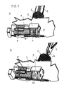
- Fig. 1 is in two parts of the figure A, B, a first embodiment of Holding device according to the invention with a by an actuator ejectable, diameter constant trigger pin 1 as a trigger member shown.
- the figure part A shows the ground state of Rollover protection system, in which the (not shown) rollover body held down against the force of a central drive compression spring 6 is, during the figure part B, the tripped state shows.
- the holding device has as a holding member on a pull rod 2, with one end in a suitable manner with the rollover body mechanically is connected (not shown).
- the tension rod 2 At the free end, the tension rod 2 a circular opening (bore) 2a, which has a diameter owns, which by a small amount larger than the diameter of the Tripping pin 1 is a non-clamping seat of the tension rod second to ensure on the trigger pin 1.
- the trigger pin 1 is mounted in a fixed bearing bracket 3 held longitudinally displaceable. Also vehicle-mounted is a bracket 4 attached to the actuator, in the illustrated embodiment is formed by a Pyroelement 5, which contains a squib, the is sensor-controlled ignited via a cable 5a.
- the figures also show the vehicle-fixed Aufstellfeder 6 in shape a coil spring, through the interior of the tension rod 2 via a Opening in the bearing block 3 with the trigger pin 1 in operative engagement can.
- the realization of the actuator by a pyrotechnic element 5 is a preferred embodiment, since this by its energy surplus sure is able to move the trigger pin, even under a strong bias of the Aufstellfedern for the rollover body.
- a pyrotechnic element 5 can also be a so-called trigger magnet or another fast drive system hydraulically, be provided pneumatically, motor.
- Fig. 2 is also in two figure parts A, B, a second embodiment illustrated in the invention, wherein the trigger pin not, as in the case of Fig. 1, diameter constant, but axially in Diameter is formed stepped.
- This stepped trigger pin 1 ' has a central portion 1'a, matched to the diameter of the bore 2a in the pull rod 2 is, and at the sides on both sides 1'b with connect smaller diameter, the right section 1'b and on the left a larger diameter portion 1'c in the bearing block 3rd the bearings of the tripping pin 1 'form.
- the hole 2a in the tension rod 2 has a slot 2b whose width on the narrower Diameter of the pin portions 1'b is tuned. Otherwise shows FIG. 2 shows the components already shown in FIG.
- the pyrotechnic element 5 ignited, it shifts ejected pin 5b the trigger pin 1 'to the right, wherein the Storage in the bearing block 3 is preserved.
- the hole 2a passes of the tension rod 2 in the pin portion 1'b with a smaller diameter. As a result, the tension rod is released via the slot 2b and can extend (figure part B).
- the trigger pin 5b and the trigger pin 1 ' can be two separate Be parts.
- the trigger pin 1 'can also be integral with the release pin 1'c be connected.
- FIG. 3 is in two parts of the figure A, B, a third embodiment the holding and releasing device according to the invention shown at the actuator 5 is formed pin-pulling and the trigger pin 1 "is firmly connected to the retractable pin
- FIG. 3 also shows that already shown in FIG Components.
- the trigger pin 1 " a continuous constant diameter, adapted to the opening 2a of the tension rod 2 on.
- the opening 2a positively connected to the trigger pin 1 ", the extension of the tension rod 2 and thus of the rollover body prevented.
- the tension rod 2 is released and can extend.
Landscapes
- Engineering & Computer Science (AREA)
- Mechanical Engineering (AREA)
- Automotive Seat Belt Assembly (AREA)
- Seats For Vehicles (AREA)
Abstract
Description
- Fig. 1
- in einer isometrischen Darstellung das erfindungsgemäße Haltesystem eines ausfahrbaren Überrollschutzsystems mit Zugstab und in einer fahrzeugfesten Halterung längs verschiebbarem Auslösezapfen im haltenden Zustand im Figurenteil A und im durch einen Aktuator ausgelösten Zustand im Figurenteil B, in einer ersten Ausführungsform des Auslösezapfens, der durchmesserkonstant ausgebildet ist und zur Auslösung aus seiner Halterung ausgestoßen wird,
- Fig. 2
- ein Haltesystem entsprechend Fig. 1, bei dem der Auslösezapfen gemäß einer zweiten Ausführungsform unterschiedliche Durchmesser-Stufen aufweist, und
- Fig. 3
- ebenfalls ein Haltesystem entsprechend Fig. 1, bei dem der Auslösezapfen gemäß einer dritten Ausführungsform, durchmesserkonstant ausgebildet, aus seiner Halterung herausziehbar angeordnet ist.
Claims (10)
- Überrollschutzsystem für Kraftfahrzeuge, mit einem verfahrbar gehalterten Überrollkörper, der im Normalzustand gegen die Kraft von mindestens einer vorgespannten Antriebs-Druckfeder durch eine Haltevorrichtung in einer unteren, eingefahrenen Ruhelage haltbar ist, und unter Lösen der Haltevorrichtung durch die Federkraft der Antriebs-Druckfeder in eine verriegelte obere, schützende Stellung bringbar ist, wobei die Haltevorrichtung ein mit dem Überrollkörper verbundenes Halteglied und ein damit in lösbarer mechanischer Wirkverbindung stehendes Auslöseglied an einem fahrzeugfesten, sensorgesteuerten Aktuator aufweist, dadurch gekennzeichnet, dass das Halteglied durch einen Zugstab (2) mit einer Bohrung (2a) am auslöseseitigen Ende und das Auslöseglied durch einen in einer fahrzeugfesten Lagerung (3) gehalterten, formschlüssig in der Bohrung (2a) aufnehmbaren und durch den Aktuator (5) in der Lagerung (3) aus einer haltenden, in eine freigebende Wirkstellung längs verschiebbaren Auslösezapfen (1, 1', 1") gebildet ist.
- Überrollschutzsystem nach Anspruch 1, dadurch gekennzeichnet, dass der Auslösezapfen (1, 1') ein separates Bauteil ist.
- Überrollschutzsystem nach Anspruch 1, dadurch gekennzeichnet, dass der Auslösezapfen (1', 1") fest mit dem Bewegungselement (5b) des Aktuators (5) verbunden ist.
- Überrollschutzsystem nach Anspruch 2, dadurch gekennzeichnet, dass der separate Auslösezapfen (1) so mit dem Bewegungselement (5b) des Aktuators (5) in Wirkverbindung steht, dass er beim Aktivieren des Aktuators (5) aus seiner fahrzeugfesten Halterung (3) von der haltenden in die freigebende Wirkverbindung ausstoßbar ist.
- Überrollschutzsystem nach Anspruch 2 oder 3, dadurch gekennzeichnet, dass der Auslösezapfen (1', 1") mit dem Bewegungselement des Aktuators (5) alternativ in die freigebende Wirkstellung vor- oder zurückverschiebbar angeordnet ist.
- Überrollschutzsystem nach Anspruch 3 und 5, dadurch gekennzeichnet, dass die Anordnung so getroffen ist, dass der Auslösezapfen (1") beim Aktivieren des Aktuators vollständig aus seiner fahrzeugfesten Halterung (3) von der haltenden in die freigebende Wirkverbindung herausziehbar ist.
- Überrollschutzsystem nach Anspruch 5, dadurch gekennzeichnet, dass der Auslösezapfen (1') zwischen seinen beiden Lagerstellen unterschiedliche, die haltende und freigebende Wirkstellung vorgebende Abschnitte (1'a, 1'b) in Verbindung mit einem Freigabeschlitz (2b) an der Öffnung (2a) des Zugstabes (2) aufweist.
- Überrollschutzsystem nach einem der Ansprüche 1 bis 7, dadurch gekennzeichnet, dass der Auslösezapfen (1, 1', 1") sowie seine Lagerstellen und die zugehörige Bohrung (2a) im Zugstab (2) kreisrund ausgebildet sind.
- Überrollschutzsystem nach Anspruch 8, dadurch gekennzeichnet, dass der Durchmesser des Auslösezapfens (1, 1") über seine axiale Länge konstant ist.
- Überrollschutzsystem nach Anspruch 7 und 8, dadurch gekennzeichnet, dass der Auslösezapfen (1') mindestens einen, den haltenden Wirkeingriff vorgebenden Abschnitt (1'a) mit einem großen, demjenigen der Bohrung (2a) im Zugstab (2) entsprechenden Durchmesser und mindestens einen davon abgesetzten, den freigebenden Wirkeingriff vorgebenden Abschnitt (1'b) kleineren Durchmessers besitzt, sowie der Zugstab (2) an seinem auslöseseitigen Ende den zur Bohrung (2a) führenden Freigabeschlitz (2b) aufweist, dessen Breite größer als der kleinere Durchmesser, aber kleiner als der größere Durchmesser des Auslösezapfens (1') ist.
Applications Claiming Priority (2)
| Application Number | Priority Date | Filing Date | Title |
|---|---|---|---|
| DE10342488 | 2003-09-10 | ||
| DE2003142488 DE10342488B4 (de) | 2003-09-10 | 2003-09-10 | Überrollschutzsystem für Kraftfahrzeuge mit einem ausfahrbaren Überrollkörper |
Publications (2)
| Publication Number | Publication Date |
|---|---|
| EP1514740A1 true EP1514740A1 (de) | 2005-03-16 |
| EP1514740B1 EP1514740B1 (de) | 2009-03-25 |
Family
ID=34129811
Family Applications (1)
| Application Number | Title | Priority Date | Filing Date |
|---|---|---|---|
| EP04021072A Expired - Lifetime EP1514740B1 (de) | 2003-09-10 | 2004-09-04 | Überrollschutzsystem für Kraftfahrzeuge mit einem ausfahrbaren Überrollkörper |
Country Status (2)
| Country | Link |
|---|---|
| EP (1) | EP1514740B1 (de) |
| DE (2) | DE10342488B4 (de) |
Cited By (1)
| Publication number | Priority date | Publication date | Assignee | Title |
|---|---|---|---|---|
| WO2012119628A1 (de) * | 2011-03-07 | 2012-09-13 | Trw Airbag Systems Gmbh | Entriegelungsvorrichtung |
Citations (2)
| Publication number | Priority date | Publication date | Assignee | Title |
|---|---|---|---|---|
| EP0657326A1 (de) * | 1993-12-13 | 1995-06-14 | ITT Automotive Europe GmbH | Überrollbügel für Kraftfahrzeuge |
| WO2002004259A1 (en) * | 2000-07-07 | 2002-01-17 | The Government Of The United States Of America As Represented By The Secretary Of The Department Of Health And Human Services, Centers For Disease Control And Prevention | Automatically deploying roll-over protection system |
Family Cites Families (4)
| Publication number | Priority date | Publication date | Assignee | Title |
|---|---|---|---|---|
| US3561806A (en) * | 1968-09-19 | 1971-02-09 | Quong Non Tse | Vehicle safety system |
| DE4342400C2 (de) * | 1993-08-03 | 2002-06-13 | Ise Gmbh | Überrollbügeleinrichtung |
| DE19838989C1 (de) * | 1998-08-27 | 1999-11-11 | Ise Gmbh | Überroll-Schutzvorrichtung |
| DE10012573C1 (de) * | 2000-03-15 | 2001-03-01 | Ise Gmbh | Haltevorrichtung für den Überrollkörper eines Überrollschutzsystems |
-
2003
- 2003-09-10 DE DE2003142488 patent/DE10342488B4/de not_active Expired - Fee Related
-
2004
- 2004-09-04 EP EP04021072A patent/EP1514740B1/de not_active Expired - Lifetime
- 2004-09-04 DE DE200450009205 patent/DE502004009205D1/de not_active Expired - Fee Related
Patent Citations (2)
| Publication number | Priority date | Publication date | Assignee | Title |
|---|---|---|---|---|
| EP0657326A1 (de) * | 1993-12-13 | 1995-06-14 | ITT Automotive Europe GmbH | Überrollbügel für Kraftfahrzeuge |
| WO2002004259A1 (en) * | 2000-07-07 | 2002-01-17 | The Government Of The United States Of America As Represented By The Secretary Of The Department Of Health And Human Services, Centers For Disease Control And Prevention | Automatically deploying roll-over protection system |
Cited By (7)
| Publication number | Priority date | Publication date | Assignee | Title |
|---|---|---|---|---|
| WO2012119628A1 (de) * | 2011-03-07 | 2012-09-13 | Trw Airbag Systems Gmbh | Entriegelungsvorrichtung |
| CN103402823A (zh) * | 2011-03-07 | 2013-11-20 | Trw空气气袋系统股份有限公司 | 解锁装置 |
| JP2014508678A (ja) * | 2011-03-07 | 2014-04-10 | ティーアールダブリュー・エアバッグ・システムズ・ゲーエムベーハー | 拘束解除デバイス |
| US9151578B2 (en) | 2011-03-07 | 2015-10-06 | Trw Airbag Systems Gmbh | Unlocking device |
| CN103402823B (zh) * | 2011-03-07 | 2017-02-22 | Trw空气气袋系统股份有限公司 | 解锁装置 |
| CN106696881A (zh) * | 2011-03-07 | 2017-05-24 | Trw空气气袋系统股份有限公司 | 解锁装置 |
| CN106696881B (zh) * | 2011-03-07 | 2019-07-05 | Trw空气气袋系统股份有限公司 | 解锁装置 |
Also Published As
| Publication number | Publication date |
|---|---|
| DE502004009205D1 (de) | 2009-05-07 |
| DE10342488A1 (de) | 2005-05-04 |
| EP1514740B1 (de) | 2009-03-25 |
| DE10342488B4 (de) | 2006-04-27 |
Similar Documents
| Publication | Publication Date | Title |
|---|---|---|
| DE19906912C1 (de) | Überroll-Schutzsystem für Kraftfahrzeuge | |
| DE69715235T2 (de) | Vorrichtung und verfahren zum insassenschutz in fahrzeugen | |
| DE102005059910B3 (de) | Überrollschutzsystem für Kraftfahrzeuge mit einem faltbaren Überrollbügel | |
| DE102017103753A1 (de) | Lenksäulenbaugruppe | |
| EP0916552B1 (de) | Ausfahrbarer Überrollbügel für Kraftfahrzeuge | |
| EP1160135B1 (de) | Überroll-Schutzsystem für Kraftfahrzeuge | |
| DE102005029253B4 (de) | Cabriolet mit einem Überrollschutzsystem | |
| DE19925520C1 (de) | Überroll-Schutzsystem für Kraftfahrzeuge | |
| EP1857332A2 (de) | Überrollschutzsystem für Kraftfahrzeuge mit mindestens einem aktiv aufstellbaren Überrollkörper | |
| DE102006028664B4 (de) | Überrollschutzsystem für ein Kraftfahrzeug | |
| EP1547873B1 (de) | Überrollschutzsystem für Kraftfahrzeuge mit einem ausfahrbaren Überrollkörper | |
| DE102006006659B3 (de) | Überrollschutzsystem für Kraftfahrzeuge mit einem annähernd fahrzeugbreiten aktiv aufstellbaren Überrollbügel | |
| DE102004012548B3 (de) | Insassenschutzvorrichtung und Verfahren zum Auslösen einer Insassenschutzvorrichtung | |
| EP1514740B1 (de) | Überrollschutzsystem für Kraftfahrzeuge mit einem ausfahrbaren Überrollkörper | |
| DE102009006876B4 (de) | Laderaumabdeckung | |
| DE102007006768A1 (de) | Überrollschutzsystem für Kraftfahrzeuge mit einem sensorgesteuert aktiv aufstellbaren Überrollkörper | |
| DE102005028879B4 (de) | Überrollschutzsystem für ein Kraftfahrzeug | |
| DE102005028966B4 (de) | Kraftfahrzeug mit einem Überrollschutzsystem an einer Fahrzeugquerwand | |
| EP1582420B1 (de) | Überrollschutzsystem für Kraftfahrzeuge mit einem ausfahrbaren Überrollkörper | |
| EP1955907B1 (de) | Überrollschutzsystem mit Überrollbügel für Kraftfahrzeuge | |
| DE102007013954A1 (de) | Überrollschutzsystem für Kraftfahrzeuge mit einem sensorgesteuert aktiv aufstellbaren Überrollkörper | |
| DE10103245C1 (de) | Überrollschutzsystem für Kraftfahrzeuge | |
| EP2384939B9 (de) | Überrollschutzsystem für Kraftfahrzeuge | |
| DE102006000909B4 (de) | Überrollschutzsystem für ein Cabriolet-Fahrzeug mit gekrümmtem Überrollkörper | |
| DE102006013913B4 (de) | Schutzvorrichtung in Kraftfahrzeugen zum Personenschutz |
Legal Events
| Date | Code | Title | Description |
|---|---|---|---|
| PUAI | Public reference made under article 153(3) epc to a published international application that has entered the european phase |
Free format text: ORIGINAL CODE: 0009012 |
|
| AK | Designated contracting states |
Kind code of ref document: A1 Designated state(s): AT BE BG CH CY CZ DE DK EE ES FI FR GB GR HU IE IT LI LU MC NL PL PT RO SE SI SK TR |
|
| AX | Request for extension of the european patent |
Extension state: AL HR LT LV MK |
|
| 17P | Request for examination filed |
Effective date: 20050428 |
|
| AKX | Designation fees paid |
Designated state(s): DE ES FR GB IT |
|
| RAP1 | Party data changed (applicant data changed or rights of an application transferred) |
Owner name: ISE AUTOMOTIVE GMBH |
|
| GRAP | Despatch of communication of intention to grant a patent |
Free format text: ORIGINAL CODE: EPIDOSNIGR1 |
|
| GRAS | Grant fee paid |
Free format text: ORIGINAL CODE: EPIDOSNIGR3 |
|
| GRAA | (expected) grant |
Free format text: ORIGINAL CODE: 0009210 |
|
| AK | Designated contracting states |
Kind code of ref document: B1 Designated state(s): DE ES FR GB IT |
|
| REG | Reference to a national code |
Ref country code: GB Ref legal event code: FG4D Free format text: NOT ENGLISH |
|
| REF | Corresponds to: |
Ref document number: 502004009205 Country of ref document: DE Date of ref document: 20090507 Kind code of ref document: P |
|
| PG25 | Lapsed in a contracting state [announced via postgrant information from national office to epo] |
Ref country code: ES Free format text: LAPSE BECAUSE OF FAILURE TO SUBMIT A TRANSLATION OF THE DESCRIPTION OR TO PAY THE FEE WITHIN THE PRESCRIBED TIME-LIMIT Effective date: 20090706 |
|
| PGFP | Annual fee paid to national office [announced via postgrant information from national office to epo] |
Ref country code: GB Payment date: 20090922 Year of fee payment: 6 |
|
| PLBE | No opposition filed within time limit |
Free format text: ORIGINAL CODE: 0009261 |
|
| STAA | Information on the status of an ep patent application or granted ep patent |
Free format text: STATUS: NO OPPOSITION FILED WITHIN TIME LIMIT |
|
| 26N | No opposition filed |
Effective date: 20091229 |
|
| PG25 | Lapsed in a contracting state [announced via postgrant information from national office to epo] |
Ref country code: DE Free format text: LAPSE BECAUSE OF NON-PAYMENT OF DUE FEES Effective date: 20100401 |
|
| PG25 | Lapsed in a contracting state [announced via postgrant information from national office to epo] |
Ref country code: IT Free format text: LAPSE BECAUSE OF FAILURE TO SUBMIT A TRANSLATION OF THE DESCRIPTION OR TO PAY THE FEE WITHIN THE PRESCRIBED TIME-LIMIT Effective date: 20090325 |
|
| GBPC | Gb: european patent ceased through non-payment of renewal fee |
Effective date: 20100904 |
|
| REG | Reference to a national code |
Ref country code: FR Ref legal event code: ST Effective date: 20110531 |
|
| PG25 | Lapsed in a contracting state [announced via postgrant information from national office to epo] |
Ref country code: FR Free format text: LAPSE BECAUSE OF NON-PAYMENT OF DUE FEES Effective date: 20100930 |
|
| PG25 | Lapsed in a contracting state [announced via postgrant information from national office to epo] |
Ref country code: GB Free format text: LAPSE BECAUSE OF NON-PAYMENT OF DUE FEES Effective date: 20100904 |
|
| PGFP | Annual fee paid to national office [announced via postgrant information from national office to epo] |
Ref country code: FR Payment date: 20091005 Year of fee payment: 6 |
|
| REG | Reference to a national code |
Ref country code: DE Ref legal event code: R081 Ref document number: 502004009205 Country of ref document: DE Owner name: METALSA AUTOMOTIVE GMBH, DE Free format text: FORMER OWNER: ISE AUTOMOTIVE GMBH, 51702 BERGNEUSTADT, DE Effective date: 20130812 |