EP1514631A1 - Méthode de vérification de la performance d'un procédé de mise en forme ou de soudage par impulsion électromagnétique - Google Patents
Méthode de vérification de la performance d'un procédé de mise en forme ou de soudage par impulsion électromagnétique Download PDFInfo
- Publication number
- EP1514631A1 EP1514631A1 EP04255456A EP04255456A EP1514631A1 EP 1514631 A1 EP1514631 A1 EP 1514631A1 EP 04255456 A EP04255456 A EP 04255456A EP 04255456 A EP04255456 A EP 04255456A EP 1514631 A1 EP1514631 A1 EP 1514631A1
- Authority
- EP
- European Patent Office
- Prior art keywords
- inductor coil
- deformation member
- magnetic pulse
- deformation
- method defined
- Prior art date
- Legal status (The legal status is an assumption and is not a legal conclusion. Google has not performed a legal analysis and makes no representation as to the accuracy of the status listed.)
- Withdrawn
Links
- 238000000034 method Methods 0.000 title claims abstract description 82
- 230000008569 process Effects 0.000 title claims abstract description 55
- 238000003466 welding Methods 0.000 title claims abstract description 40
- 238000012544 monitoring process Methods 0.000 title claims description 7
- 238000005259 measurement Methods 0.000 claims description 8
- 230000004044 response Effects 0.000 claims description 7
- 230000005489 elastic deformation Effects 0.000 abstract description 4
- 230000005672 electromagnetic field Effects 0.000 description 31
- 230000006698 induction Effects 0.000 description 7
- 239000003990 capacitor Substances 0.000 description 5
- 239000004020 conductor Substances 0.000 description 5
- 239000012530 fluid Substances 0.000 description 4
- 238000006073 displacement reaction Methods 0.000 description 3
- 230000008901 benefit Effects 0.000 description 2
- 230000008859 change Effects 0.000 description 2
- 239000007769 metal material Substances 0.000 description 2
- 238000003070 Statistical process control Methods 0.000 description 1
- 230000003466 anti-cipated effect Effects 0.000 description 1
- 230000000593 degrading effect Effects 0.000 description 1
- 238000004146 energy storage Methods 0.000 description 1
- 238000011156 evaluation Methods 0.000 description 1
- 238000003780 insertion Methods 0.000 description 1
- 230000037431 insertion Effects 0.000 description 1
Images


Classifications
-
- B—PERFORMING OPERATIONS; TRANSPORTING
- B23—MACHINE TOOLS; METAL-WORKING NOT OTHERWISE PROVIDED FOR
- B23K—SOLDERING OR UNSOLDERING; WELDING; CLADDING OR PLATING BY SOLDERING OR WELDING; CUTTING BY APPLYING HEAT LOCALLY, e.g. FLAME CUTTING; WORKING BY LASER BEAM
- B23K9/00—Arc welding or cutting
- B23K9/09—Arrangements or circuits for arc welding with pulsed current or voltage
-
- B—PERFORMING OPERATIONS; TRANSPORTING
- B23—MACHINE TOOLS; METAL-WORKING NOT OTHERWISE PROVIDED FOR
- B23K—SOLDERING OR UNSOLDERING; WELDING; CLADDING OR PLATING BY SOLDERING OR WELDING; CUTTING BY APPLYING HEAT LOCALLY, e.g. FLAME CUTTING; WORKING BY LASER BEAM
- B23K20/00—Non-electric welding by applying impact or other pressure, with or without the application of heat, e.g. cladding or plating
- B23K20/06—Non-electric welding by applying impact or other pressure, with or without the application of heat, e.g. cladding or plating by means of high energy impulses, e.g. magnetic energy
-
- B—PERFORMING OPERATIONS; TRANSPORTING
- B23—MACHINE TOOLS; METAL-WORKING NOT OTHERWISE PROVIDED FOR
- B23K—SOLDERING OR UNSOLDERING; WELDING; CLADDING OR PLATING BY SOLDERING OR WELDING; CUTTING BY APPLYING HEAT LOCALLY, e.g. FLAME CUTTING; WORKING BY LASER BEAM
- B23K2101/00—Articles made by soldering, welding or cutting
- B23K2101/04—Tubular or hollow articles
- B23K2101/06—Tubes
-
- Y—GENERAL TAGGING OF NEW TECHNOLOGICAL DEVELOPMENTS; GENERAL TAGGING OF CROSS-SECTIONAL TECHNOLOGIES SPANNING OVER SEVERAL SECTIONS OF THE IPC; TECHNICAL SUBJECTS COVERED BY FORMER USPC CROSS-REFERENCE ART COLLECTIONS [XRACs] AND DIGESTS
- Y10—TECHNICAL SUBJECTS COVERED BY FORMER USPC
- Y10T—TECHNICAL SUBJECTS COVERED BY FORMER US CLASSIFICATION
- Y10T29/00—Metal working
- Y10T29/49—Method of mechanical manufacture
- Y10T29/49803—Magnetically shaping
Definitions
- This invention relates in general to the use of magnetic pulse forming techniques that can be used to deform a metallic workpiece to a desired shape.
- This invention also relates in general to the use of magnetic pulse welding techniques that can be used to permanently secure two metallic workpieces together.
- this invention relates to a method and apparatus for monitoring the performance of a magnetic pulse forming process or a magnetic pulse welding process over a period of time and for adjusting the parameters of such magnetic pulse forming or welding processes when necessary to maintain consistency in the operation thereof.
- Magnetic pulse forming and magnetic pulse welding are well known processes that can be used in connection with workpieces that are formed from metallic materials.
- Magnetic pulse forming techniques are typically used to deform a metallic workpiece to a desired shape.
- a magnetic pulse forming process is performed by initially disposing a portion of a metallic workpiece either about or within an electromagnetic inductor coil. The inductor coil is then energized by a passing a high-energy pulse of electrical current therethrough so as to generate an intense electromagnetic field either about or within the portion of the workpiece.
- the workpiece may be deformed inwardly into engagement with an inner mandrel or outwardly into engagement with an outer die so that the workpiece is deformed to have a precise desired shape.
- Magnetic pulse welding techniques are typically used to permanently secure two metallic workpieces together.
- a magnetic pulse welding process is performed by initially disposing two portions of first and second metallic workpieces in a concentric, axially overlapping relationship.
- the overlapping portions of the first and second metallic workpieces are disposed either about or within an electromagnetic inductor coil.
- the inductor coil is then energized by a passing a high-energy pulse of electrical current therethrough so as to generate an intense electromagnetic field either about or within the overlapping portions of the first and second workpieces.
- a large pressure is exerted on one of the first and second workpieces, causing it to move toward the other of the first and second workpieces at a high velocity.
- the inductor coil is disposed about the exterior of the two workpieces, then the outer workpiece is deformed inwardly into engagement with the inner workpiece. If, on the other hand, the inductor coil is disposed within the interior of the two workpieces, then the inner workpiece is deformed outwardly into engagement with the outer workpieces. In either event, the high velocity impact of the first and second workpieces cause the two workpieces to become permanently secured together.
- magnetic pulse forming techniques and magnetic pulse welding techniques result in the generation of high energy electromagnetic fields either about or within the workpiece or workpieces.
- the inductor coil be manufactured in such a manner as to be very strong from a mechanically standpoint.
- the repeated generation of such reactance forces can cause physical changes to occur in the magnetic pulse forming or welding apparatus.
- the shape or spatial orientation of the inductor coil can change slightly as a result of the repeated generation of these reactance forces.
- This invention relates to a method and apparatus for monitoring the performance of a magnetic pulse forming process or a magnetic pulse welding process over a period of time and for adjusting the parameters of such magnetic pulse forming or welding processes when necessary to maintain consistency in the operation thereof.
- the parameters of such processes can be monitored by positioning a deformation member relative to an inductor coil of the apparatus, then energizing the inductor coil to exert a force thereon.
- the deformation member can be a plastically deformable tube, and the amount of such plastic deformation that occurs when the inductor coil is energized can be measured to determine the magnitude of the force that is generated by the inductor coil.
- the deformation member can be an elastically deformable body, and the amount of such elastic deformation that occurs when the inductor coil is energized can be measured to determine the magnitude of the force that is generated by the inductor coil.
- the magnitude of the force that is generated by the inductor coil is representative of the performance of the magnetic pulse forming or welding process and can be used, when necessary, to adjust the parameters of the magnetic pulse forming or welding processes to maintain consistency in the operation thereof.
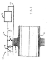
- Fig. 1 is a sectional elevational view schematically illustrating an inductor and a control circuit of an apparatus for performing a magnetic pulse forming process or magnetic pulse welding process, together with a first embodiment of a deformation member in accordance with this invention that can be used to monitor the performance of such processes, wherein the first embodiment of the deformation member is shown before the inductor coil has been energized.
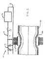
- Fig. 2 is a schematic view similar to Fig. 1, wherein the first embodiment of the deformation member is shown after the inductor coil has been energized.
- Fig. 3 is a schematic view similar to Fig. 2, wherein a measurement gauge is shown inserted within the first embodiment of the deformation member.
- Fig. 4 is an end elevational view schematically illustrating the inductor of the apparatus for performing a magnetic pulse forming process or magnetic pulse welding process illustrated in Fig. 1, together with a second embodiment of a deformation member in accordance with this invention that can be used to monitor the performance of such processes.
- Fig. 5 is an end elevational view similar to Fig. 4 of a third embodiment of a deformation member in accordance with this invention.
- Fig. 6 is an end elevational view similar to Fig. 5 of a fourth embodiment of a deformation member in accordance with this invention.
- Fig. 7 is a sectional elevational view of the fourth embodiment of the deformation member taken along line 7-7 of Fig. 6.
- Fig. 1 a portion of an apparatus, indicated generally at 10, for performing a magnetic pulse forming process or magnetic pulse welding process.
- the apparatus 10 is, of itself, conventional in the art, and the illustrated apparatus 10 is intended to be representative of any structure for performing a magnetic pulse forming process or magnetic pulse welding process. Thus, the scope of this invention is not intended to be limited for use with the specific apparatus 10 illustrated in Fig. 1.
- the illustrated apparatus 10 includes an inductor coil 11 that is adapted to be disposed about or within a metallic workpiece (not shown).
- the inductor coil 11 can be formed having any desired structure, such as that shown and described in U.S. Patent No. 4,129,846 to Yablochnikov. The disclosure of that patent is incorporated herein by reference.
- the inductor coil 11 is connected to a schematically illustrated control circuit for selectively operating same. To accomplish this, a first end of the inductor coil 11 is connected to a first electrical conductor 12, while a second end of the inductor coil 11 is connected through a discharge switch 13 to a second electrical conductor 14. A plurality of high voltage capacitors 15 or other energy storage devices are connected between the first and second electrical conductors 12 and 14. The first electrical conductor 12 is also connected to a source of electrical power 16, while the second electrical conductor 14 is connected through a charging switch 17 to the source of electrical power 16.
- the structure and operation of the control circuit is described in detail in U.S. Patent No. 5,981,921 to Yablochnikov, and the disclosure of that patent is also incorporated herein by reference.
- the inductor coil 11 is operated by initially opening the discharge switch 13 and closing the charging switch 17, as shown in Fig. 1. This allows electrical energy to be transferred from the source of electrical power 16 to each of the capacitors 15.
- the charging switch 17 is opened, as shown in Fig. 2.
- the discharge switch 13 is closed, as also shown in Fig. 2.
- a high energy pulse of electrical current flows from the capacitors 15 through the inductor coil 11, thereby generating an immense and momentary electromagnetic field about or within the workpiece.
- the inductor coil 11 is sized and shaped to be disposed concentrically about the workpiece.
- the inductor coil 11 may be sized and shaped to be disposed concentrically within the workpiece. In this instance, when the inductor coil 11 is energized and the electromagnetic field is generated, a very large force is exerted on the inner surface of the workpiece, causing it to expand outwardly away from the inductor coil 11.
- the inductor coil 11 may be used either to perform a magnetic pulse forming process, wherein the workpiece is deformed to a desired shape, or a magnetic pulse welding process, wherein two metallic workpieces are permanently secured together, as described in detail above.
- both the magnetic pulse forming process and the magnetic pulse welding process result in the generation of high energy electromagnetic fields either about or within the workpiece or workpieces.
- the inductor coil 11 be manufactured in such a manner as to be very strong from a mechanical standpoint.
- the repeated generation of such reactance forces can cause physical changes to occur in the magnetic pulse forming or welding apparatus 10.
- the shape or spatial orientation of the inductor coil 11 can change slightly as a result of these reactance forces.
- a method and apparatus are provided for monitoring the performance of the apparatus 10 as it performs the magnetic pulse forming processes or the magnetic pulse welding processes over a period of time and for adjusting the parameters of such magnetic pulse forming or welding processes when necessary to maintain consistency in the operation of such processes.
- the method and apparatus of this invention are effective to periodically measure the magnitudes of the forces that are generated by the electromagnetic field on the workpiece and to compare such measurements in order to determine if changes occur in the intensity of the electromagnetic field. If any such changes occurs, the operation of the apparatus 10 can be adjusted to compensate therefor.
- Fig. 1 illustrates a first embodiment of a deformation member 20 that can be used in accordance with this invention to monitor the performance of the magnetic pulse forming or welding apparatus 10.
- the deformation member 20 is initially disposed concentrically within the illustrated inductor coil 11, as shown in Fig. 1.
- the deformation member 20 can be initially disposed concentrically about the inductor coil 11.
- the deformation member 20 can be embodied as any structure that is capable of being deformed by the apparatus 10 when the inductor coil 11 is energized in the manner described above.
- the deformation member 20 is embodied as a hollow cylindrical tube that is formed from a metallic material.
- the apparatus 10 is operated so as to energize the inductor coil 11 in the manner described above.
- the portion of the deformation member 20 that is disposed within the inductor coil 11 is deformed radially inwardly, such as shown at 20a in Fig. 2.
- the amount of such deformation of the deformed portion 20a will depend upon the overall performance of the apparatus 10. If the apparatus 10 generates an electromagnetic field of relatively high intensity, then the magnitudes of the forces exerted on the deformation member 20 will be relatively large, resulting in a relatively large amount of deformation.
- the apparatus 10 If, on the other hand, the apparatus 10 generates an electromagnetic field of relatively low intensity, then the magnitudes of the forces exerted on the deformation member 20 will be relatively small, resulting in a relatively small amount of deformation.
- a determination can be made as to the strength of the electromagnetic field generated by the inductor coil 11.
- the amount of deformation that occurs in the deformed portion 20a of the deformation member 20 can be measured in any desired manner.
- a simple measurement gauge 21 can be inserted within the deformation member 20 to determine the amount of deformation that has occurred.
- the gauge 21 is conventional in the art and can be embodied as any structure having a predetermined size or shape.
- the gauge 21 can provide a pass/no pass indication of the magnitude of the internal dimension of the deformed portion 20a of the deformation member 20. Because the internal configuration of the deformed portion 20a of the deformation member 20 may be non-uniform, the evaluation of its internal dimension is preferably accomplished using a gauge 21 having a cylindrical outer surface.
- the gauge 21 cannot pass through the deformed portion 20a of the deformation member 20, then it can be determined that the strength of the electromagnetic field generated by the inductor coil 11 is sufficiently strong as to insure that the magnetic pulse forming process or the magnetic pulse welding process is being performed properly. In this instance, use of the apparatus 10 can be continued in the normal manner without adjustment. If, on the other hand, the gauge 21 can pass through the deformed portion 20a of the deformation member 20 (or alternatively pass through the deformed portion 20a of the deformation member 20 with a substantial amount of play therebetween), then it can be determined that the strength of the electromagnetic field generated by the inductor coil 11 is not sufficiently strong as to insure that the magnetic pulse forming process or the magnetic pulse welding process is being performed properly.
- the apparatus 10 it may be necessary or desirable to adjust one or more of the above-described components of the apparatus 10 to increase the strength of the electromagnetic field generated by the inductor coil 11 before continuing in the normal manner.
- This adjustment of the components of the apparatus 10 can be accomplished in any desired manner, including increasing the power supplied by the source of electrical power 16, varying the capacitance of the bank of capacitors 15, and the like.
- a plurality of different sized gauges can be used to precisely measure the internal dimension of the deformed portion 20a of the deformation member 20.
- a plurality of different sized gauges By using a plurality of different sized gauges, more precise information regarding the strength of the electromagnetic field generated by the inductor coil 11 can be collected. For example, instead of a simple pass/no pass determination of the strength of the electromagnetic field generated by the inductor coil 11, the use of a plurality of differently sized gauges would allow the strength of the electromagnetic field generated by the inductor coil 11 to be more precisely quantified. This, in turn, would allow more informative decisions to be made regarding the operation of the apparatus 10.
- the use of a plurality of differently sized gauges would allow a determination to be made that even though the apparatus 10 is functioning within acceptable parameters, the strength of the electromagnetic field generated by the inductor coil 11 is degrading over a period of time. As a result, adjustments to the apparatus 10 can be anticipated and corrected before a failure mode is reached. Also, the use of a plurality of differently sized gauges would facilitate the use of other process monitoring tools, such as statistical process controls and the like.
- the deformation member 20 is plastically deformed as a result of the energization of the inductor coil 11.
- the deformation member 20 is deformed to such an extent that the deformed portion 20a retains its deformed shape after the inductor coil 11 is ceased to be energized.
- the inductor coil 11 can be energized to cause only elastic deformation of the deformation member 11, wherein the deformation member 30 is deformed to such an extent that the deformed portion returns to its original shape after the inductor coil 11 is ceased to be energized.
- the inductor 11 of the apparatus 10 for performing a magnetic pulse forming process or magnetic pulse welding process is illustrated with a second embodiment of a deflection member, indicated generally at 30, that can be used in accordance with this invention to monitor the performance of such processes.
- energization of the inductor coil 11 causes only elastic deformation of the deformation member 30.
- the deformation member 30 is deformed to such an extent that the deformed portion returns to its original shape after the inductor coil 11 is ceased to be energized.
- the second embodiment of the deformation member 30 includes a body 31 having an opening 32 formed therein.
- the body 31 is generally cylindrical in shape, and the opening 32 extends throughout the longitudinal axis of the body 31.
- the body 31 of the deformation member 30 may be formed having any desired shape, and the opening 32 may be formed in any desired location or orientation within the body 31.
- a sensor 33 is disposed within the central opening 32 of the body 31 of the deformation member 30.
- the sensor 33 can be embodied as any conventional displacement, force, strain, pressure, or other sensing device that is responsive to the application of force to the body 31 of the deformation member 30 for generating a signal that is representative of the magnitude thereof.
- the sensor 33 can be embodied as a conventional piezo-electric sensor.
- the deformation member 30 is initially disposed concentrically within the inductor coil 11, as shown in Fig. 4.
- the apparatus 10 is operated so as to energize the inductor coil 11 in the manner described above.
- the portion of the deformation member 30 that is disposed within the inductor coil 11 is elastically deformed radially inwardly, resulting in compressive forces being exerted on the sensor 33.
- the amount of such deformation and compressive forces will depend upon the overall performance of the apparatus 10. If the apparatus 10 generates an electromagnetic field of relatively high intensity, then the magnitudes of the forces exerted on the deformation member 30 will be relatively large, resulting in a relatively large amount of deformation.
- the apparatus 10 If, on the other hand, the apparatus 10 generates an electromagnetic field of relatively low intensity, then the magnitudes of the forces exerted on the deformation member 30 will be relatively small, resulting in a relatively small amount of deformation.
- the sensor 33 is responsive to the magnitude of such deformation for generating the signal that is representative thereof.
- This sensor signal is, therefore, representative of the strength of the electromagnetic field generated by the inductor coil 11.
- the sensor signal can be used in the manner described above to monitor the performance of the magnetic pulse forming or welding process and, when necessary, to adjust the apparatus 10 or the other parameters of the magnetic pulse forming or welding processes to maintain consistency in the operation thereof.
- the senor 33 can be supported within the opening 32 of the body 31 by one or more inserts 34.
- two of such supporting inserts 34 are provided about the sensor 33 within the opening 32.
- the abutting surfaces of the interior of the opening 32 and the supporting inserts 34 engage one another so as to establish a pre-loading force against the sensor 33.
- This mechanical pre-loading force not only assures that the various components of the deformation member 30 are properly assembled together, but also functions to minimize or eliminate any small gaps that might be present in the abutting surfaces that could result in incorrect readings by the sensor 33.
- either or both of the abutting surfaces of the interior of the opening 32 and either or both of the supporting inserts 34 are tapered so as to facilitate the establishment of a precise magnitude of this pre-loading force against the sensor 33, although such is not required.
- slits or other openings may be formed in the body 31 thereof.
- a first pair of opposed slits 35 are formed in the body 31 of the deformation member 30, each extending generally radially outwardly from the central opening 32 and terminating in an enlarged area 35a that is located near the outer surface of the body 31.
- a second pair of opposed slits 36 are formed in the body 31 of the deformation member 30, each extending generally radially inwardly from the outer surface of the body 31 and terminating in an enlarged area 36a that is located near the central opening 32.
- the slits 35 and 36 enhance the flexibility of the deformation member 30 so that portions of the body 31 will be more greatly deformed in response to the application of force thereto.
- a sensor may be provided to directly measure the magnitude of the electromagnetic field that is generated by the inductor coil 11.
- a conventional induction gauge 37 is disposed within the enlarged area 36a of one of the slits 36. If desired, however, the induction gauge 37 may be disposed at any other desired location.
- the induction gauge 37 is adapted to generate a signal that is representative of the magnitude of the electromagnetic field that is generated by the inductor coil 11 when energized. The signal from the induction gauge 37 may be helpful in interpreting the results of the deformation measurement.
- Fig. 5 is an end elevational view similar to Fig. 4 of a third embodiment of a deflection member, indicated generally at 40, in accordance with this invention.
- the third embodiment of the deformation member 40 includes a body 41 having an opening (not shown) formed therein.
- the body 41 is generally cylindrical in shape, and the opening extends throughout the longitudinal axis of the body 41.
- the body 41 of the deformation member 40 may be formed having any desired shape, and the opening may be formed in any desired location or orientation within the body 41.
- a sensor, indicated generally at 42 is disposed within the central opening of the body 41 of the deformation member 40.
- the sensor 42 can be embodied as any conventional displacement, force, strain, pressure, or other sensing device that is responsive to the application of force to the body 41 of the deformation member 40 for generating a signal that is representative of the magnitude thereof.
- slits or other openings may be formed in the body 41 thereof.
- a plurality of slits 43 are formed in the body 41 of the deformation member 40, each extending generally radially outwardly from the central opening and terminating in an enlarged area 43 a that is located near the outer surface of the body 41.
- six of such slits 43 are equidistantly formed about the deformation member 40.
- the slits 43 enhance the flexibility of the deformation member 40 so that portions of the body 41 will be more greatly deformed in response to the application of force thereto. Otherwise, the deformation member 40 functions in the same manner as the deformation member described above.
- Fig. 6 is an end elevational view similar to Fig. 4 of a fourth embodiment of a deflection member, indicated generally at 50, in accordance with this invention.
- the fourth embodiment of the deformation member 50 includes a body 51 having an opening 52 (see Fig. 7) formed therein.
- the body 51 is generally cylindrical in shape, and the opening 52 extends throughout the longitudinal axis of the body 51.
- the body 51 of the deformation member 50 may be formed having any desired shape, and the opening 52 may be formed in any desired location or orientation within the body 51.
- a sensor, indicated generally at 53, is disposed within the central opening 52 of the body 51 of the deformation member 50.
- the sensor 53 can be embodied as any conventional displacement, force, strain, pressure, or other sensing device that is responsive to the application of force to the body 51 of the deformation member 50 for generating a signal that is representative of the magnitude thereof.
- the structure of the sensor 53 will be described in further detail below.
- slits or other openings may be formed in the body 51 thereof.
- a plurality of slits 54 are formed in the body 51 of the deformation member 50, each extending generally radially inwardly from the outer surface of the body 51 and terminating in an enlarged area 54 a that is located near the central opening 52.
- six of such slits 54 are equidistantly formed about the deformation member 50.
- the slits 54 enhance the flexibility of the deformation member 50 so that portions of the body 51 will be more greatly deformed in response to the application of force thereto. Otherwise, the deformation member 50 functions in the same manner as the deformation member described above.
- a sensor may be provided to directly measure the magnitude of the electromagnetic field that is generated by the inductor coil 11.
- a conventional induction gauge 55 is disposed within the enlarged area 54a of one of the slits 54.
- the induction gauge 55 is adapted to generate a signal that is representative of the magnitude of the electromagnetic field that is generated by the inductor coil 11 when energized.
- the signal from the induction gauge 55 may be used in the manner described above.
- the structure of the sensor 53 is illustrated in detail.
- the sensor 53 includes a pair of plugs 61 and 62 that close the ends of the central opening 52 formed through the body 51 of the deformation member 50 to define a chamber that contains a quantity of a fluid 63.
- a valve 64 such as a conventional check valve, is provided in the first plug 61 for facilitating the insertion of the fluid 63 within the chamber.
- a sensor 65 such as a conventional fluid pressure sensor, is provided in the second plug 62 for measuring the pressure of the fluid 63 contained within the chamber, which will vary in accordance with deformations of the deformation member 50 as described above.
Landscapes
- Engineering & Computer Science (AREA)
- Mechanical Engineering (AREA)
- Physics & Mathematics (AREA)
- Plasma & Fusion (AREA)
- Measuring Fluid Pressure (AREA)
- Pressure Welding/Diffusion-Bonding (AREA)
- Force Measurement Appropriate To Specific Purposes (AREA)
Applications Claiming Priority (2)
| Application Number | Priority Date | Filing Date | Title |
|---|---|---|---|
| US50177003P | 2003-09-10 | 2003-09-10 | |
| US501770P | 2003-09-10 |
Publications (1)
| Publication Number | Publication Date |
|---|---|
| EP1514631A1 true EP1514631A1 (fr) | 2005-03-16 |
Family
ID=34135381
Family Applications (1)
| Application Number | Title | Priority Date | Filing Date |
|---|---|---|---|
| EP04255456A Withdrawn EP1514631A1 (fr) | 2003-09-10 | 2004-09-09 | Méthode de vérification de la performance d'un procédé de mise en forme ou de soudage par impulsion électromagnétique |
Country Status (5)
| Country | Link |
|---|---|
| US (1) | US7026585B2 (fr) |
| EP (1) | EP1514631A1 (fr) |
| CN (1) | CN1621175A (fr) |
| IL (1) | IL163974A0 (fr) |
| RU (1) | RU2004127164A (fr) |
Cited By (1)
| Publication number | Priority date | Publication date | Assignee | Title |
|---|---|---|---|---|
| CN101653803B (zh) * | 2008-08-22 | 2011-03-02 | 首都航天机械公司 | 波纹管端口磁脉冲精密校形装置 |
Families Citing this family (11)
| Publication number | Priority date | Publication date | Assignee | Title |
|---|---|---|---|---|
| US7263757B2 (en) * | 2004-04-15 | 2007-09-04 | General Motors Corporation | Electromagnetic trimming, flanging and hemming apparatus and method |
| FR2912000A1 (fr) * | 2007-01-31 | 2008-08-01 | Powerconn | Cable de raccordement de poles de batterie |
| US8414406B2 (en) | 2010-07-19 | 2013-04-09 | Dana Automotive Systems Group, Llc | Constant velocity joint assembly and method of securing a shaft to the assembly |
| CN102486509A (zh) * | 2010-12-01 | 2012-06-06 | 首都航天机械公司 | 磁脉冲成形感应器寿命试验方法 |
| CN104014923B (zh) * | 2014-06-11 | 2016-06-01 | 中国航空工业集团公司北京航空制造工程研究所 | 一种铝合金扩散连接方法 |
| US9676054B2 (en) | 2014-08-08 | 2017-06-13 | Ford Global Technologies, Llc | Electrode cartridge for pulse welding |
| US9421636B2 (en) * | 2014-12-19 | 2016-08-23 | Ford Global Technologies, Llc | Pulse joining cartridges |
| CN105789728B (zh) * | 2014-12-23 | 2020-07-10 | 比亚迪股份有限公司 | 一种电池液冷板及其制备方法以及电池模组、电池包和电动汽车 |
| FR3075674B1 (fr) * | 2017-12-26 | 2019-12-13 | Adm28 S.Ar.L | Procede d’assemblage d’une bague dans une piece tubulaire par impulsion magnetique |
| JP6793148B2 (ja) * | 2018-04-12 | 2020-12-02 | 矢崎総業株式会社 | 電磁圧接端子の製造方法 |
| CN108274108B (zh) * | 2018-04-17 | 2019-05-10 | 福州大学 | 电磁脉冲焊接金属橡胶阻尼夹芯管的装置及其工作方法 |
Citations (2)
| Publication number | Priority date | Publication date | Assignee | Title |
|---|---|---|---|---|
| US4962656A (en) * | 1989-06-30 | 1990-10-16 | The United States Of America As Represented By The United States Department Of Energy | Control and monitoring method and system for electromagnetic forming process |
| US20020116817A1 (en) * | 2000-10-12 | 2002-08-29 | Hardesty Jeffrey B. | Method of manufacturing an exhaust emission control device |
Family Cites Families (12)
| Publication number | Priority date | Publication date | Assignee | Title |
|---|---|---|---|---|
| US3267580A (en) | 1961-04-21 | 1966-08-23 | Woodworth Co N A | Adjustable bore gauge |
| US3251974A (en) * | 1963-03-28 | 1966-05-17 | Ohio Crankshaft Co | Metal forming apparatus |
| DE2113720C3 (de) * | 1971-03-22 | 1980-09-11 | Siemens Ag, 1000 Berlin Und 8000 Muenchen | Verfahren zur Durchmesserregelung beim tiegellosen Zonenschmelzen von Halbleiterstäben |
| US4129846A (en) | 1975-08-13 | 1978-12-12 | Yablochnikov B | Inductor for magnetic pulse working of tubular metal articles |
| US4075755A (en) | 1976-11-11 | 1978-02-28 | S&C Electric Company | High voltage fuse and method of attaching tubular members therein |
| US4192534A (en) | 1976-11-11 | 1980-03-11 | S & C Electric Company | High voltage fuse having attached tubular members |
| US4200987A (en) | 1978-10-10 | 1980-05-06 | Schmitt Marvin G | Gauge |
| JPH0651599B2 (ja) * | 1987-12-05 | 1994-07-06 | 信越半導体株式会社 | 浮遊帯域制御方法 |
| US4807351A (en) | 1988-02-18 | 1989-02-28 | Asea Composites, Inc. | Method for attaching an end-fitting to a drive shaft tube |
| US5824998A (en) | 1995-12-20 | 1998-10-20 | Pulsar Welding Ltd. | Joining or welding of metal objects by a pulsed magnetic force |
| US5981921A (en) | 1997-06-20 | 1999-11-09 | Dana Corporation | Method of magnetic pulse welding an end fitting to a driveshaft tube of a vehicular driveshaft |
| US6400538B1 (en) | 2000-03-03 | 2002-06-04 | Inli, Llc | Energy storage apparatus for magnetic pulse welding and forming |
-
2004
- 2004-09-08 IL IL16397404A patent/IL163974A0/xx unknown
- 2004-09-09 CN CNA2004101023191A patent/CN1621175A/zh active Pending
- 2004-09-09 EP EP04255456A patent/EP1514631A1/fr not_active Withdrawn
- 2004-09-09 RU RU2004127164/02A patent/RU2004127164A/ru not_active Application Discontinuation
- 2004-09-10 US US10/938,033 patent/US7026585B2/en not_active Expired - Lifetime
Patent Citations (2)
| Publication number | Priority date | Publication date | Assignee | Title |
|---|---|---|---|---|
| US4962656A (en) * | 1989-06-30 | 1990-10-16 | The United States Of America As Represented By The United States Department Of Energy | Control and monitoring method and system for electromagnetic forming process |
| US20020116817A1 (en) * | 2000-10-12 | 2002-08-29 | Hardesty Jeffrey B. | Method of manufacturing an exhaust emission control device |
Cited By (1)
| Publication number | Priority date | Publication date | Assignee | Title |
|---|---|---|---|---|
| CN101653803B (zh) * | 2008-08-22 | 2011-03-02 | 首都航天机械公司 | 波纹管端口磁脉冲精密校形装置 |
Also Published As
| Publication number | Publication date |
|---|---|
| IL163974A0 (en) | 2005-12-18 |
| CN1621175A (zh) | 2005-06-01 |
| US7026585B2 (en) | 2006-04-11 |
| RU2004127164A (ru) | 2006-02-20 |
| US20050051539A1 (en) | 2005-03-10 |
Similar Documents
| Publication | Publication Date | Title |
|---|---|---|
| US7026585B2 (en) | Method for monitoring the performance of a magnetic pulse forming or welding process | |
| KR102255129B1 (ko) | 파스너 | |
| US4889679A (en) | Eddy current probe apparatus having an expansible sleeve | |
| US5490406A (en) | Crimping tool having die bottoming monitor | |
| US6707304B2 (en) | Devices and methods for detecting a processing electrode of a machine tool | |
| US9823148B2 (en) | Force-measuring device | |
| CN115183798B (zh) | 用于线性可变差动变压器(lvdt)探针的c形圆柱形芯 | |
| US5386442A (en) | Method and apparatus for controlling the load on double cantilever beam sensors | |
| CN107024533A (zh) | 用于确定管的完整性的设备和方法 | |
| JP7288918B2 (ja) | 電気導体への接触を認識する装置、電気導体への接触を認識する方法、このような種類の装置を有するストリッピング機械 | |
| PL205309B1 (pl) | Narzędzie do osadzania ze środkami do kontroli operacji osadzania, głowica dla narzędzia do osadzania oraz sposób kontroli operacji osadzania, zwłaszcza operacji osadzania nitów, a także sposób kontroli nitu, zwłaszcza dla narzędzia do osadzania | |
| CN105612021B (zh) | 间接感测焊接紧固件位置的焊机 | |
| EP3025134A2 (fr) | Système de mesure d'une force axiale d'un assemblage à vis | |
| GB1573952A (en) | Acoustic warning device | |
| US10937585B2 (en) | Electromagnetic device | |
| JP7366386B2 (ja) | ワーク挙動検出機能を備えたクランプシステム | |
| CN109070360B (zh) | 工具更换装置和工具更换系统 | |
| JP5188472B2 (ja) | 電磁成形コイル、電磁成形コイルの成形可能寿命診断方法 | |
| JP5403611B2 (ja) | 水中作業装置及び水中用歪計測装置 | |
| EP1710546B1 (fr) | Procédé de mesure de la variation de longueur d'un ressort et ressort possédant un capteur correspondant | |
| EP3817886B1 (fr) | Procédé permettant de commander un agencement de soudage par points et agencement de soudage par points | |
| JPH0284276A (ja) | 抵抗溶接機の電極加圧装置 | |
| US20050068136A1 (en) | Methods for the production of a pressure pipe of an electric hoisting magnet and pressure pipe of a hoisting magnet | |
| Schäfer et al. | Electromagnetic pulse forming technology. Keys for allocating the industrial market segment | |
| EP3096421B1 (fr) | Méthode de fabrication de bougie d'allumage |
Legal Events
| Date | Code | Title | Description |
|---|---|---|---|
| PUAI | Public reference made under article 153(3) epc to a published international application that has entered the european phase |
Free format text: ORIGINAL CODE: 0009012 |
|
| AK | Designated contracting states |
Kind code of ref document: A1 Designated state(s): AT BE BG CH CY CZ DE DK EE ES FI FR GB GR HU IE IT LI LU MC NL PL PT RO SE SI SK TR |
|
| AX | Request for extension of the european patent |
Extension state: AL HR LT LV MK |
|
| 17P | Request for examination filed |
Effective date: 20050912 |
|
| AKX | Designation fees paid |
Designated state(s): AT BE BG CH CY CZ DE DK EE ES FI FR GB GR HU IE IT LI LU MC NL PL PT RO SE SI SK TR |
|
| 17Q | First examination report despatched |
Effective date: 20070719 |
|
| STAA | Information on the status of an ep patent application or granted ep patent |
Free format text: STATUS: THE APPLICATION IS DEEMED TO BE WITHDRAWN |
|
| 18D | Application deemed to be withdrawn |
Effective date: 20071130 |