EP1514586A1 - Mittels Ultraschallverschweissung hergestelltes Filtermedium - Google Patents
Mittels Ultraschallverschweissung hergestelltes Filtermedium Download PDFInfo
- Publication number
- EP1514586A1 EP1514586A1 EP04020213A EP04020213A EP1514586A1 EP 1514586 A1 EP1514586 A1 EP 1514586A1 EP 04020213 A EP04020213 A EP 04020213A EP 04020213 A EP04020213 A EP 04020213A EP 1514586 A1 EP1514586 A1 EP 1514586A1
- Authority
- EP
- European Patent Office
- Prior art keywords
- layer
- filter
- layers
- filtration
- filtration media
- Prior art date
- Legal status (The legal status is an assumption and is not a legal conclusion. Google has not performed a legal analysis and makes no representation as to the accuracy of the status listed.)
- Withdrawn
Links
- 238000001914 filtration Methods 0.000 title claims abstract description 107
- 238000003466 welding Methods 0.000 title claims description 13
- 239000012530 fluid Substances 0.000 claims abstract description 45
- 239000000463 material Substances 0.000 claims abstract description 31
- 238000000034 method Methods 0.000 claims abstract description 22
- 238000004519 manufacturing process Methods 0.000 claims abstract description 8
- 230000005540 biological transmission Effects 0.000 claims description 25
- 239000002245 particle Substances 0.000 claims description 13
- 239000010410 layer Substances 0.000 description 105
- 229920000728 polyester Polymers 0.000 description 23
- 239000000835 fiber Substances 0.000 description 13
- 239000000853 adhesive Substances 0.000 description 12
- 230000001070 adhesive effect Effects 0.000 description 12
- 239000011230 binding agent Substances 0.000 description 8
- 230000035939 shock Effects 0.000 description 7
- 239000013618 particulate matter Substances 0.000 description 5
- 239000011148 porous material Substances 0.000 description 5
- 238000007373 indentation Methods 0.000 description 3
- 230000036619 pore blockages Effects 0.000 description 3
- 230000000903 blocking effect Effects 0.000 description 2
- 238000003490 calendering Methods 0.000 description 2
- 238000011118 depth filtration Methods 0.000 description 2
- 230000007717 exclusion Effects 0.000 description 2
- 239000004744 fabric Substances 0.000 description 2
- 238000002844 melting Methods 0.000 description 2
- 230000008018 melting Effects 0.000 description 2
- 239000002356 single layer Substances 0.000 description 2
- 125000006850 spacer group Chemical group 0.000 description 2
- KXGFMDJXCMQABM-UHFFFAOYSA-N 2-methoxy-6-methylphenol Chemical group [CH]OC1=CC=CC([CH])=C1O KXGFMDJXCMQABM-UHFFFAOYSA-N 0.000 description 1
- 229920000877 Melamine resin Polymers 0.000 description 1
- 239000004677 Nylon Substances 0.000 description 1
- 230000001154 acute effect Effects 0.000 description 1
- 239000004568 cement Substances 0.000 description 1
- 239000002131 composite material Substances 0.000 description 1
- 239000000356 contaminant Substances 0.000 description 1
- 238000011109 contamination Methods 0.000 description 1
- 238000010586 diagram Methods 0.000 description 1
- 230000000694 effects Effects 0.000 description 1
- 239000004816 latex Substances 0.000 description 1
- 229920000126 latex Polymers 0.000 description 1
- 239000007788 liquid Substances 0.000 description 1
- JDSHMPZPIAZGSV-UHFFFAOYSA-N melamine Chemical compound NC1=NC(N)=NC(N)=N1 JDSHMPZPIAZGSV-UHFFFAOYSA-N 0.000 description 1
- 229920001778 nylon Polymers 0.000 description 1
- 239000011236 particulate material Substances 0.000 description 1
- 230000000149 penetrating effect Effects 0.000 description 1
- ISWSIDIOOBJBQZ-UHFFFAOYSA-N phenol group Chemical group C1(=CC=CC=C1)O ISWSIDIOOBJBQZ-UHFFFAOYSA-N 0.000 description 1
- 239000005011 phenolic resin Substances 0.000 description 1
- 229920001568 phenolic resin Polymers 0.000 description 1
- 230000000979 retarding effect Effects 0.000 description 1
- 239000002904 solvent Substances 0.000 description 1
- 230000003068 static effect Effects 0.000 description 1
- 230000005641 tunneling Effects 0.000 description 1
- 238000009941 weaving Methods 0.000 description 1
Images
Classifications
-
- B—PERFORMING OPERATIONS; TRANSPORTING
- B01—PHYSICAL OR CHEMICAL PROCESSES OR APPARATUS IN GENERAL
- B01D—SEPARATION
- B01D39/00—Filtering material for liquid or gaseous fluids
- B01D39/08—Filter cloth, i.e. woven, knitted or interlaced material
- B01D39/083—Filter cloth, i.e. woven, knitted or interlaced material of organic material
-
- B—PERFORMING OPERATIONS; TRANSPORTING
- B01—PHYSICAL OR CHEMICAL PROCESSES OR APPARATUS IN GENERAL
- B01D—SEPARATION
- B01D39/00—Filtering material for liquid or gaseous fluids
- B01D39/14—Other self-supporting filtering material ; Other filtering material
- B01D39/16—Other self-supporting filtering material ; Other filtering material of organic material, e.g. synthetic fibres
- B01D39/1607—Other self-supporting filtering material ; Other filtering material of organic material, e.g. synthetic fibres the material being fibrous
- B01D39/1623—Other self-supporting filtering material ; Other filtering material of organic material, e.g. synthetic fibres the material being fibrous of synthetic origin
-
- B—PERFORMING OPERATIONS; TRANSPORTING
- B01—PHYSICAL OR CHEMICAL PROCESSES OR APPARATUS IN GENERAL
- B01D—SEPARATION
- B01D2239/00—Aspects relating to filtering material for liquid or gaseous fluids
- B01D2239/06—Filter cloth, e.g. knitted, woven non-woven; self-supported material
- B01D2239/065—More than one layer present in the filtering material
- B01D2239/0677—More than one layer present in the filtering material by spot-welding
-
- B—PERFORMING OPERATIONS; TRANSPORTING
- B01—PHYSICAL OR CHEMICAL PROCESSES OR APPARATUS IN GENERAL
- B01D—SEPARATION
- B01D2239/00—Aspects relating to filtering material for liquid or gaseous fluids
- B01D2239/06—Filter cloth, e.g. knitted, woven non-woven; self-supported material
- B01D2239/069—Special geometry of layers
-
- B—PERFORMING OPERATIONS; TRANSPORTING
- B01—PHYSICAL OR CHEMICAL PROCESSES OR APPARATUS IN GENERAL
- B01D—SEPARATION
- B01D2239/00—Aspects relating to filtering material for liquid or gaseous fluids
- B01D2239/08—Special characteristics of binders
- B01D2239/086—Binders between particles or fibres
-
- B—PERFORMING OPERATIONS; TRANSPORTING
- B01—PHYSICAL OR CHEMICAL PROCESSES OR APPARATUS IN GENERAL
- B01D—SEPARATION
- B01D2239/00—Aspects relating to filtering material for liquid or gaseous fluids
- B01D2239/10—Filtering material manufacturing
-
- B—PERFORMING OPERATIONS; TRANSPORTING
- B01—PHYSICAL OR CHEMICAL PROCESSES OR APPARATUS IN GENERAL
- B01D—SEPARATION
- B01D2239/00—Aspects relating to filtering material for liquid or gaseous fluids
- B01D2239/12—Special parameters characterising the filtering material
- B01D2239/1216—Pore size
-
- B—PERFORMING OPERATIONS; TRANSPORTING
- B01—PHYSICAL OR CHEMICAL PROCESSES OR APPARATUS IN GENERAL
- B01D—SEPARATION
- B01D2239/00—Aspects relating to filtering material for liquid or gaseous fluids
- B01D2239/12—Special parameters characterising the filtering material
- B01D2239/1291—Other parameters
Definitions
- the present invention relates to a filter, a method of manufacturing a filtration media and a method of filtration using the filter. More particularly, the invention relates to a filter including at least two layers of filtration material assembled together by sonic welding, and a method of manufacturing a filtration media by assembling at least two layers of filtration media and sonically welding the layers together.
- Multilayer filtration materials are useful as fluid filters, for example, as particulate filters for use in automobiles.
- Multilayer filtration also known as serial filtration, may be used in automobile transmission fluid filters.
- Automatic transmissions require a filter to remove contaminating particulate materials, generated during the operation of the automatic transmission.
- Current serial filtration media for use in automobile transmission filters include a layer of polyester felt and a layer of screen held together by a scrim of low melting point polyester adhesive, typically melting at 120°C.
- the polyester adhesive has a negative impact on the flow and pressure drop in the filter.
- the polyester adhesive when applied under heat and pressure to bond the felt layer with the screen layer, oozes into the felt and screen pores, partially blocking the pores in the filtration media.
- the pressure from the adhesive application rollers causes the openings in the felt to be squeezed into a smaller size. Both the partial pore blockage and the pore squeezing that occur during the adhesive application affect the flow, the pressure drop and the particle size intercepted. Uneven pore blockage from the adhesive application can lead to further filtration problems, including uneven fluid flow across the filter, and dumping of contamination through the filter due to hydraulic, thermal, and mechanical shock.
- a filter and a method of manufacturing a filter have been invented which overcome the aforementioned problems.
- the filter and the method of manufacturing the filter allow for holding together of at least two materials using a sonic weld.
- the filtration material thus does not require the addition of adhesive, and the problems associated with adhesive in the filter material.
- the invention is a filtration media comprising a layer of felt and a layer of woven screen assembled on top of one another wherein the at least two layers are held together with a sonic weld.
- the invention is a filter comprising a housing, at least two layers of non-identical filtration material, assembled on top of one another, disposed within the housing, and the at least two layers of filtration material are held together with a sonic weld.
- the invention is a method of manufacturing a filtration media effective in trapping particles of about 70 microns and larger, by placing at least two layers of filtration material on top of one another and applying a sonic weld across a surface of the filtration media to hold together the at least two layers.
- the invention is a method of filtration comprising the steps of providing a filter, the filter having a housing, and at least two layers of filtration material assembled on top of one another, disposed within the housing, wherein the at least two layers of filtration material are held together with a sonic weld; and passing a fluid through the filter housing such that the fluid passes through the filtration material.
- the present invention solves the problems of the partial pore blockage and the pore squeezing by eliminating the need for adhesive in forming a serial filtration media. Further advantages of the present invention will become apparent in the description of the invention.
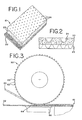
- FIG. 1 is a perspective view of a preferred filtration media of the present invention
- FIG. 2 is a side elevational view of the filtration media of FIG 1;
- FIG. 3 is a schematic diagram illustrating a method and apparatus for manufacturing the filtration media of FIG. 1;
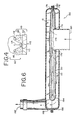
- FIG. 4 is an enlarged, partial side elevational view of the apparatus of FIG. 2;
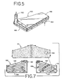
- FIG. 5 is a perspective view of a transmission filter of a preferred embodiment of the present invention.
- FIG. 6 is a cross-sectional view of the transmission filter of FIG. 5.
- FIG. 7 is a top view assembly drawing of the parts making up the transmission filter of FIG. 5.
- FIGS. 1 and 2 A preferred embodiment of the filtration media 10 of the present invention is shown in FIGS. 1 and 2.
- the filtration media 10 is a composite formed by assembling a layer of polyester felt 20 on top of a layer of woven screen 22 and holding together the layers together using sonic welding.
- a plurality of weld spots 24, resulting from the sonic welding process, are shown in the layer of polyester felt 20.
- the layer of polyester felt 20 is a depth filtration media of polyester mechanically entangled felt. The depth filtration media of the present invention allows the particulate matter in the filtration fluid to be captured at many layers within the layer of polyester felt 20, retarding the blockage of the filtration media.
- the nominal rating for the preferred particle size exclusion of the layer 20 is about 40 to 70 microns, more preferably about 70 microns.
- the preferred thickness for the layer 20 is about 50 to 100 mils, more preferably about 100 mils.
- the preferred layer 20 is manufactured as follows.
- the diameter of the starting polyester fiber threads used to form the layer 20 is in the range from about 2-6 deniers, more preferably about 4 3/4 denier of yarn.
- a binder is added to the polyester fiber threads to hold the fibers in place.
- the preferred binder is a phenolic resin that is inert to transmission fluid.
- a latex binder, a melamine binder, or any binder commonly known in the art may be used to hold the fibers in place.
- the layer of polyester felt formed from the fibers with the added phenolic binder is then heat cured to evaporate the solvents.
- the layer of polyester felt 20 is then calendered to compact the felt and thereby control the size of the particle exclusion cut off and the thickness of the layer 20.
- the layer 20 may be sonically welded to the woven screen 22 without calendering.
- the flow rate of the layer of polyester felt 20 is determined as a measure of the density of the layer 20.
- the desired flow rate of the filtration media 10 depends on the fluid to be filtered, the contaminating particle size cutoff, the flow rate of the layer of polyester felt, the layer of woven screen 22 to be used and the filter unit into which the filtration media 10 is inserted for use.
- the layer 20 may be preferably manufactured in rolls to be fed into a sonic welding apparatus (described below).
- the layer 20 may be used in the filtration media 10 as a single layer, or alternatively, the layer 20 may be folded over double and held together with the layer 22 with sonic welds.
- the preferred layer of woven screen 22 may be a square weave fabric, although there are numerous types of weaving patterns.
- the woven screen 22 is defined herein by the micron rating, which is the distance across the opening between the fibers, and the percent open area, which is determined by the diameter of the fiber used to weave the screen.
- the micron rating for the screen is from about 40 microns to about 500 microns, more preferably about 80 microns.
- the percent open area is from about 30% to about 50%, more preferably about 40%.
- the preferred material for the woven screen is polyester, although nylon or other materials known to one of skill in the art may also be used.
- the fibers of the woven screen 22 may have a binder to keep the fibers in place, or the woven screen my be heat set with heat and pressure to flatten the fibers where the fibers pass over and under each other and to lock the fibers in place.
- the preferred layer of woven screen is obtainable from Sefar, International Fabric Company, or Satti.
- the layer of woven screen 22 provides additional support for the layer of polyester felt 20 and helps prevent the layer 20 from stretching over time with use, thereby changing the filtration characteristics of the layer 20.
- the layer 22 held together with the layer 20 also may help provide support to the layer 20 to help prevent dumping of particulate matter accumulated in the layer 20 when hydraulic or mechanical shock occurs to the filtration media 10.
- the particulate In the normal course of filtering particulate matter from a fluid, the particulate is intercepted by the media and collects or builds up, or accretes on the media surface and in the interstitial spaces of the filter media, referred to as loading of the media or caking of the media.
- the particulate stays in place on the media due to an equilibrium of forces on the particulate and not due to the addition of any binder or cement.
- the larger particles will tend to block some of the opening in the media and smaller particles that normally would pass through the media become trapped in the smaller openings created during accretion.
- the efficiency of the media increases as the filtration media becomes loaded with particulate.
- a mechanical or hydraulic shock is applied to a system that has collected particulate, the particulate matter is energized and becomes suspended again in the fluid.
- the layer 22, held together with the layer 20 by sonic welding helps to prevent stretching and dumping due to shock and fluid movement by collecting particulate in the weld spots 24 created by the sonic weld.
- the particulate is collected in the weld spots 24, less particulate is released and energized during shock, allowing the filtration media to filter the appropriate sized particle.
- the filtration media 10 may include additional layers of filtration material held together with the layers 20 and 22.
- the additional layers of filtration material may be held together on top of the layer 20, between the layers 20 and 22, or beneath the layer 22.
- Each additional layer of filtration material may be a depth media or a layer of woven screen, or any filtration media commonly known in the art.
- the additional layer of filtration media may require alternative sonic weld conditions.
- the filtration media 10 may also be pleated after welding for use in a filtration unit.
- FIG. 3 illustrates an apparatus 50 and a method employed to sonically weld the layer of polyester felt 20 to the layer of woven screen 22 to create the preferred filtration media 10.
- An important aspect of the present invention is the ability to weld together the layer of polyester felt 20 and the layer of woven screen 22 using an ultrasonic welding process and thereby eliminating the need for adhesives to hold together the layers that comprise the filtration media 10. It has been found that by proper design of the sonic weld apparatus 50, the layer of polyester felt 20 and the layer of woven screen 22 may be held together without the addition of adhesives, thereby eliminating the problems due to adhesives used in the process of holding together the layers, such as partial blocking of the pores in the filtration media.
- a sonic welding apparatus 50 of a preferred embodiment is shown in FIG. 3.
- the apparatus 50 comprises a roller 60 having a plurality of protrusions 62 and an ultrasonic horn 64 attached to a sonic driver 66.
- the roller 60 operates continually to feed the polyester felt layer 20 assembled on top of the woven screen layer 22 through the apparatus 50.
- the operation of the roller 60 may be indexed.
- the plurality of protrusions 62 contact the layer 20.
- the protrusions 62 pull the layer 20, which is assembled on top of the layer 22, through the apparatus 50.
- the plurality of protrusions 62 are truncated cone-shaped.
- An exemplary truncated cone-shaped protrusion 62 contacting the layer of polyester felt 20 is illustrated in FIG. 4.
- each protrusion has a flat, round apex 110 that is about 0.025 to 0.25 inches in diameter 112, preferably about 0.025 inches.
- the apex 110 abuts the flat surface of the ultrasonic horn 64 to form the plurality of sonic weld spots to hold the layer 20 together with the layer 22.
- the preferred plurality of sonic weld spots occlude less than about 1 % of the surface area for the filtration media 10.
- the preferred protrusions 62 extend from the roller 60 a distance 114 of about 1/8 inch.
- the sides of the cone-shaped protrusions 62 may be at an acute angle 116, preferably about a 30° angle, with respect to the contact plane of the layer 20 as shown in FIG. 4. It has been found that the conical shape prevents tearing of the fibers of the layer 20 when the plurality of protrusions 62 contact and release the layer 20 as the layer 20, assembled on top of the layer 22, moves through the apparatus 50.
- the plurality of protrusions 62 may be varied in shape, pattern, size and number.
- the preferred roller 60 is about 4 inches in diameter and about 5 feet wide to accommodate rolls of the layer 20 and the layer 22. Alternative roller sizes are possible and may be preferred depending on the layers 20 and 22 to be sonically welded.
- the ultrasonic horn 64 may be a relatively smooth flat bar, the size of the flat bar corresponds to the width the roller 60 used in a particular embodiment of the present invention.
- the bar of the ultrasonic horn 64 is a flat bar about one inch wide and five feet long.
- the ultra sonic horn may be a roller with a relatively smooth surface wherein the sonic weld is formed to hold together the layers 20 and 22 at the contact points between the plurality of protrusions 62 on the roller 60 and the relatively smooth surface of the roller ultrasonic horn.
- the ultrasonic horn 64 is vibrated by the sonic driver 66.
- the frequency of the ultrasonic horn 64 is about 10,000 to 40,000 cycles per second, more preferably about 20,000 cycles per second.
- the preferred weld cycle time for the ultrasonic horn 64 depends on variables such as the speed of the roller 60 feeding the layers 20 and 22 through the apparatus 50, the type and thickness of the materials comprising the layers 20 and 22, the engagement force of the roller 60 and the amplitude of the ultrasonic horn 64.
- FIG. 2 shows a side elevation view of the filtration media 10 after the layer 20 is held together with the layer 22.
- the plurality of weld spots 24 are shown as conical indentations in the layer 20. As shown, the indentations formed in the layer 20 by the protrusions 62 during the sonic welding are preferably uniform across the filter. Additional benefits of the indentations formed include improved media flow through the filter.
- the plurality of weld spots 24 may act as traps to capture particulate and other contaminants in the fluid passing through the filtration media 10.
- the plurality of weld spots 24 may also help to promote cold flow of fluid through the filtration media 10 by increasing the surface area and partially penetrating the felt.
- the plurality of weld spots 24 may help prevent tunneling that occurs when the layer of polyester felt 20 may become eroded by concentrated fluid, flow such as in the area of the inlet or outlet of a filter unit.
- FIG. 5 illustrates a transmission fluid filter 150 of a preferred embodiment of the present invention.
- the transmission fluid filter 150 may be used in an automatic transmission of an automobile.
- the transmission fluid filter 150 is designed to be placed in a transmission fluid sump area on the inlet side of the fluid pump. As shown, the filter 150 includes an inlet 160 on the bottom side and an outlet 162 extends from the top of the transmission fluid filter 150.
- the filter 150 also includes a base member 166 and a cover member 168.
- FIG. 6 illustrates the filtration media 10 of the present invention in the transmission filter 150.
- the filtration media 10 may be built into the transmission fluid filter 150.
- U.S. Patent Nos. 4,826,598 and 5,049,274 describe transmission fluid filters in which the filtration media 10 can be used and are hereby incorporated herein by reference.
- the filtration media 10 is enclosed within a volume 164 formed between the base member 166 and the cover member 168 of the transmission fluid filter 150.
- the filtration media 10 is fashioned into an elongated, rectangular sheet, folded in half, and forming an envelope. The edges of the filtration media 10 are sealingly captured between the junction of flanged edges 170 and 172 around an opening 174.
- the ends 176 and 178 of the filtration media 10 are held together between the base member 166 and the cover member 168, which are sealed together by overmold 180.
- FIG. 7 illustrates a top view assembly drawing of the filter 150.
- the filtration media 10 is shaped so that it can be doubled over inside the filter.
- the unfolded edges on three sides are sealingly captured between the peripheries of the base member 166 and the cover member 168.
- An elliptical hole 190 is provided through the filtration media 10 of the same shape and size as the opening 174 in the base member 166.
- the base member 166 includes generally parallel fluid flow spacer elements 192 extending up from and integral with the base wall 194.
- the cover member 168 also includes generally parallel flow spacer elements 196 extending downwardly from and integral with the cover wall 198.
- the preferred flow rate is determined. The determinations described herein are for the filter described in U.S. Patent No. 5,049,274.
- the vacuum decay in the preferred embodiment, may decay less than about 50 mm Hg/minute.
- the transmission fluid filter 150 is tested with viscous fluid, at -40°F, the filtration media 10, in the preferred embodiment, may withstand about 635 mm Hg without being loosened at the junction of the flanged edges 170 and 172.
- the filtration media 10 also be inserted into other filtration devices commonly known in the art.
Landscapes
- Chemical & Material Sciences (AREA)
- Chemical Kinetics & Catalysis (AREA)
- Engineering & Computer Science (AREA)
- Textile Engineering (AREA)
- Filtering Materials (AREA)
Applications Claiming Priority (2)
| Application Number | Priority Date | Filing Date | Title |
|---|---|---|---|
| US10/652,896 US20050045566A1 (en) | 2003-08-29 | 2003-08-29 | Filtration media created by sonic welding |
| US652896 | 2003-08-29 |
Publications (1)
| Publication Number | Publication Date |
|---|---|
| EP1514586A1 true EP1514586A1 (de) | 2005-03-16 |
Family
ID=34136643
Family Applications (1)
| Application Number | Title | Priority Date | Filing Date |
|---|---|---|---|
| EP04020213A Withdrawn EP1514586A1 (de) | 2003-08-29 | 2004-08-26 | Mittels Ultraschallverschweissung hergestelltes Filtermedium |
Country Status (2)
| Country | Link |
|---|---|
| US (1) | US20050045566A1 (de) |
| EP (1) | EP1514586A1 (de) |
Cited By (2)
| Publication number | Priority date | Publication date | Assignee | Title |
|---|---|---|---|---|
| CN102451589A (zh) * | 2010-11-02 | 2012-05-16 | 东丽纤维研究所(中国)有限公司 | 一种耐热性过滤材料及其生产方法和用途 |
| CN102481502A (zh) * | 2009-08-10 | 2012-05-30 | 旭化成纤维株式会社 | 集尘机用过滤布 |
Families Citing this family (21)
| Publication number | Priority date | Publication date | Assignee | Title |
|---|---|---|---|---|
| US7264713B2 (en) * | 2003-09-03 | 2007-09-04 | Thomas Kryzak | Apparatus, system and method for remediation of contamination |
| DE102007023641B4 (de) * | 2007-05-22 | 2015-04-02 | Ibs Filtran Kunststoff-/ Metallerzeugnisse Gmbh | Ölfiltervorrichtung |
| US8287729B2 (en) * | 2008-04-28 | 2012-10-16 | California Polytechnic Corporation | Field water purification system |
| US9132225B2 (en) | 2009-01-15 | 2015-09-15 | Brightwake Limited | Cardiopulmonary bypass circuit including a filtration device |
| WO2011060377A1 (en) | 2009-11-15 | 2011-05-19 | Solera Networks, Inc. | Method and apparatus for real time identification and recording of artifacts |
| CN105996782A (zh) | 2010-07-22 | 2016-10-12 | K-Fee系统股份有限公司 | 具有标识符的分配胶囊 |
| IT1401966B1 (it) * | 2010-09-24 | 2013-08-28 | Gvs Spa | Dispositivo filtrante perfezionato per pompa carburante di un veicolo. |
| DE102011111738A1 (de) * | 2011-08-26 | 2013-02-28 | Neenah Gessner Gmbh | Mehrlagiges Filtermaterial und daraus hergestelltes Filterelement |
| DE102012105282A1 (de) | 2012-06-18 | 2013-12-19 | K-Fee System Gmbh | Portionskapsel und Verfahren zur Herstellung eines Getränks mit einer Portionskapsel |
| JP5985300B2 (ja) * | 2012-08-10 | 2016-09-06 | 愛三工業株式会社 | 燃料フィルタ装置 |
| DE102012223291A1 (de) | 2012-12-14 | 2014-06-18 | K-Fee System Gmbh | Portionskapsel und Verfahren zur Herstellung eines Getränks mit einer Portionskapsel |
| EP2835163B1 (de) * | 2013-08-09 | 2016-10-12 | Eurofilters N.V. | Filterbeutel für einen staubsauger sowie verfahren zur ermittlung einer unmittelbar angeströmten fläche eines staubsaugerfilterbeutels |
| EP3145611B1 (de) * | 2014-05-22 | 2020-08-26 | Kuss Filtration Inc. | Herstellung von filtermedien zur aufrechterhaltung des durchflusses durch einen sockenfilter |
| CA2951753C (en) * | 2014-06-12 | 2020-11-10 | K-Fee System Gmbh | Portion capsule comprising a calendered fibre-like material |
| ES2733814T5 (es) | 2015-02-27 | 2023-02-14 | K Fee System Gmbh | Cápsula para porciones con un elemento de filtro unido mediante sellado |
| ES2747752T3 (es) | 2015-06-10 | 2020-03-11 | K Fee System Gmbh | Cápsula con un velo de tres capas |
| MX2018000149A (es) | 2015-07-13 | 2018-03-23 | K Fee System Gmbh | Elemento filtrante con una escotadura. |
| CA2998669C (en) | 2015-09-18 | 2020-01-07 | K-Fee System Gmbh | Adapter for a single serve capsule |
| US10932903B2 (en) | 2017-08-15 | 2021-03-02 | Edwards Lifesciences Corporation | Skirt assembly for implantable prosthetic valve |
| WO2020020756A1 (de) | 2018-07-27 | 2020-01-30 | K-Fee System Gmbh | Verfahren zur herstellung einer portionskapsel zur zubereitung eines getränks in einer getränkeherstellungsmaschine, portionskapsel und verfahren zur herstellung eines getränks mit einer getränkezubereitungsmaschine und einer portionskapsel |
| EP3883865B2 (de) | 2018-11-22 | 2025-11-05 | GCS German Capsule Solution GmbH | Dichtung einer portionskapsel |
Citations (5)
| Publication number | Priority date | Publication date | Assignee | Title |
|---|---|---|---|---|
| US4250039A (en) * | 1979-05-07 | 1981-02-10 | Wire Cloth Products, Inc. | Transmission filter |
| DE4443158A1 (de) * | 1994-12-05 | 1996-06-13 | Gessner & Co Gmbh | Abreinigbares Filtermedium |
| US5900305A (en) * | 1997-01-24 | 1999-05-04 | Chapman; Rick L. | Laminated high efficiency filter |
| US20030106295A1 (en) * | 2001-12-08 | 2003-06-12 | Ibs Filtran Kunststoff-/Metallerzeugnisse Gmbh | Multilayer composite filter medium for serial filtration |
| EP1331030A1 (de) * | 2002-01-17 | 2003-07-30 | 3M Innovative Properties Company | Elektrostatisch geladenes Filterfaservlies und Verfahren zu seiner Herstellung |
Family Cites Families (37)
| Publication number | Priority date | Publication date | Assignee | Title |
|---|---|---|---|---|
| US2057779A (en) * | 1933-11-28 | 1936-10-20 | Edwin F Jacobs | Gasoline purifying means |
| US2418247A (en) * | 1941-03-17 | 1947-04-01 | Cherry Burrell Corp | Tubular detachable filter |
| US3310173A (en) * | 1963-11-04 | 1967-03-21 | Tri Men Mfg Corp | Apparatus for removing sediment from swimming pools |
| US3382984A (en) * | 1965-10-04 | 1968-05-14 | Kuss & Co R L | Filter construction |
| US3688908A (en) * | 1971-01-28 | 1972-09-05 | Robert R Myers | Filter device for a submergible swimming pool cleaner |
| US3841489A (en) * | 1973-05-02 | 1974-10-15 | Kuss R And Co Inc | Fluid filter |
| US4052315A (en) * | 1974-10-21 | 1977-10-04 | Illinois Tool Works Inc. | One-piece molded filter |
| USRE30779E (en) * | 1977-12-05 | 1981-10-20 | Pall Corporation | Filter assembly with replaceable filter element |
| US4211661A (en) * | 1979-01-08 | 1980-07-08 | Chave & Earley, Inc. | Filter medium |
| US4288012A (en) * | 1979-09-06 | 1981-09-08 | Doak Roni K | Coathanger suspender |
| US4402827A (en) * | 1980-07-11 | 1983-09-06 | Sealed Power Corporation | Transmission fluid filter |
| US4640771A (en) * | 1982-11-04 | 1987-02-03 | Caterpillar, Inc. | Fluid intake screening device |
| EP0190012B1 (de) * | 1985-01-25 | 1993-01-07 | Asahi Kasei Kogyo Kabushiki Kaisha | Nichtgewobene Stoffbahn, Öl-Wasser-Trennungsfilter und Verfahren zur Öl-Wasser-Trennung |
| US4608166A (en) * | 1985-04-01 | 1986-08-26 | Filtertek, Inc. | Press fit filter |
| US4776904A (en) * | 1985-07-19 | 1988-10-11 | Miles Inc. | Multilayer analytical element and method of making, using ultrasonic or laser energy |
| JPS6242713A (ja) * | 1985-08-14 | 1987-02-24 | Aisin Warner Ltd | インラインストレ−ナ |
| US4826598A (en) * | 1985-11-29 | 1989-05-02 | Filtertek, Inc. | Hermetically sealed transmission filter |
| US5049274A (en) * | 1988-01-11 | 1991-09-17 | Filtertek, Inc. | Friction welding process and filter formed thereby |
| US4828694A (en) * | 1988-01-11 | 1989-05-09 | Filtertek, Inc. | Filter with filtration envelope spacing means |
| JP2717271B2 (ja) * | 1988-07-25 | 1998-02-18 | アイシン・エィ・ダブリュ株式会社 | 自動変速機用オイルストレーナ、並びにそれを用いた自動変速機 |
| US4985142A (en) * | 1989-12-15 | 1991-01-15 | Sundstrand Corporation | Quick release filter by-pass valve |
| US5049271A (en) * | 1990-08-27 | 1991-09-17 | Filtertek, Inc. | Fuel tank filter |
| US5534145A (en) * | 1991-04-09 | 1996-07-09 | Sweetwater, Inc. | Compact water filtration pump |
| DE69215795T2 (de) * | 1991-08-16 | 1997-04-03 | Stanadyne Automotive Corp | Tropfwassergeschütztes Austauschsystem für Kraftstoffilter |
| US5419953A (en) * | 1993-05-20 | 1995-05-30 | Chapman; Rick L. | Multilayer composite air filtration media |
| US5435957A (en) * | 1993-09-03 | 1995-07-25 | Pall Corporation | Method of preparing a support material for use with a filtration medium |
| JP3068743B2 (ja) * | 1994-03-24 | 2000-07-24 | 本田技研工業株式会社 | フィルター装置 |
| US5533478A (en) * | 1994-04-13 | 1996-07-09 | Siemens Automotive L.P. | Discrete filter and pressure regulator mounting for a fuel rail |
| US5582907A (en) * | 1994-07-28 | 1996-12-10 | Pall Corporation | Melt-blown fibrous web |
| US5540985A (en) * | 1995-03-10 | 1996-07-30 | The Trenton Corporation | Protective sheet material and method for making same |
| US5716522A (en) * | 1996-10-25 | 1998-02-10 | Kuss Corporation | Non-woven depth media in-tank fuel filter |
| US5902480A (en) * | 1997-05-13 | 1999-05-11 | Kuss Corporation | Depth media in-tank fuel filter with extruded mesh shell |
| CA2231066C (en) * | 1998-01-09 | 2004-05-11 | Andrew J. Boast | Monolithic molded plastic component adapted for receiving an o-ring |
| US6267252B1 (en) * | 1999-12-08 | 2001-07-31 | Kimberly-Clark Worldwide, Inc. | Fine particle filtration medium including an airlaid composite |
| DE10008692C2 (de) * | 2000-02-24 | 2002-03-14 | Ibs Filtran Kunststoff Metall | Ölwanne für Motoren oder Getriebe |
| EP1238693B1 (de) * | 2001-03-02 | 2007-06-20 | Filtertek Inc. | Ölwannenfilter mit Filterpatrone |
| US7282140B2 (en) * | 2001-03-02 | 2007-10-16 | Filtertek Inc. | Sump filter with filter element cartridge |
-
2003
- 2003-08-29 US US10/652,896 patent/US20050045566A1/en not_active Abandoned
-
2004
- 2004-08-26 EP EP04020213A patent/EP1514586A1/de not_active Withdrawn
Patent Citations (5)
| Publication number | Priority date | Publication date | Assignee | Title |
|---|---|---|---|---|
| US4250039A (en) * | 1979-05-07 | 1981-02-10 | Wire Cloth Products, Inc. | Transmission filter |
| DE4443158A1 (de) * | 1994-12-05 | 1996-06-13 | Gessner & Co Gmbh | Abreinigbares Filtermedium |
| US5900305A (en) * | 1997-01-24 | 1999-05-04 | Chapman; Rick L. | Laminated high efficiency filter |
| US20030106295A1 (en) * | 2001-12-08 | 2003-06-12 | Ibs Filtran Kunststoff-/Metallerzeugnisse Gmbh | Multilayer composite filter medium for serial filtration |
| EP1331030A1 (de) * | 2002-01-17 | 2003-07-30 | 3M Innovative Properties Company | Elektrostatisch geladenes Filterfaservlies und Verfahren zu seiner Herstellung |
Cited By (5)
| Publication number | Priority date | Publication date | Assignee | Title |
|---|---|---|---|---|
| CN102481502A (zh) * | 2009-08-10 | 2012-05-30 | 旭化成纤维株式会社 | 集尘机用过滤布 |
| EP2476472A4 (de) * | 2009-08-10 | 2013-06-05 | Asahi Kasei Fibers Corp | Filterungstuch für eine staubsammelmaschine |
| US8795403B2 (en) | 2009-08-10 | 2014-08-05 | Asahi Kasei Fibers Corporation | Filter cloth for dust collector |
| CN102451589A (zh) * | 2010-11-02 | 2012-05-16 | 东丽纤维研究所(中国)有限公司 | 一种耐热性过滤材料及其生产方法和用途 |
| CN102451589B (zh) * | 2010-11-02 | 2015-09-09 | 东丽纤维研究所(中国)有限公司 | 一种耐热性过滤材料及其生产方法和用途 |
Also Published As
| Publication number | Publication date |
|---|---|
| US20050045566A1 (en) | 2005-03-03 |
Similar Documents
| Publication | Publication Date | Title |
|---|---|---|
| EP1514586A1 (de) | Mittels Ultraschallverschweissung hergestelltes Filtermedium | |
| KR102916913B1 (ko) | 다공성 멤브레인을 포함하는 필터 백 | |
| CN102006917B (zh) | 过滤复合材料及其制造方法和由过滤复合材料制成的扁平过滤元件 | |
| US5605748A (en) | Fiber beds for fiber bed mist eliminators | |
| KR101152511B1 (ko) | 다층 필터 매체 | |
| US4211661A (en) | Filter medium | |
| KR970000365B1 (ko) | 측로 개구부가 구비된 여과 시이트를 이용한 유연성 필터 부재 | |
| US20100212273A1 (en) | Vacuum Cleaner Filter Bag | |
| JP4317347B2 (ja) | 自動変速機用オイルフィルタの濾過材 | |
| US20040035095A1 (en) | Filter media | |
| US7981296B2 (en) | Methods of using geotextile composite for filtration of contaminated liquids and sediments | |
| JP2008526495A (ja) | ミスト分離器のための繊維床型捕集帯状媒体 | |
| CN1729101A (zh) | 具有改进的静电消散的水力缠绕过滤介质及其制造方法 | |
| WO2009062009A2 (en) | Meltblown filter medium | |
| JP2005512781A (ja) | 直列式濾過のための多層複合フィルタエレメント | |
| NZ205709A (en) | Filter assembly with convoluted filter element | |
| JP4152642B2 (ja) | 自動車用燃料フィルター材および自動車用燃料フィルター | |
| WO1997034678A1 (en) | Self-sealing liquid filter | |
| US20190070541A1 (en) | Filter material and filtration assembly | |
| JPH08500528A (ja) | 基層により支持された多孔質薄膜を含むろ過媒体及びその製造方法 | |
| JP4359059B2 (ja) | 自動変速機用オイルフィルタの濾過材 | |
| JP3994225B2 (ja) | 濾過材および濾過方法 | |
| US12090430B2 (en) | Method of producing a multilayer filter medium and a filter medium produced in accordance with this method | |
| DE202010009671U1 (de) | Schmelzblas-Filtermaterial, zugehörige Einsatzmöglichkeiten und Verwendungen | |
| JP3644812B2 (ja) | 筒状フィルタ |
Legal Events
| Date | Code | Title | Description |
|---|---|---|---|
| PUAI | Public reference made under article 153(3) epc to a published international application that has entered the european phase |
Free format text: ORIGINAL CODE: 0009012 |
|
| AK | Designated contracting states |
Kind code of ref document: A1 Designated state(s): AT BE BG CH CY CZ DE DK EE ES FI FR GB GR HU IE IT LI LU MC NL PL PT RO SE SI SK TR |
|
| AX | Request for extension of the european patent |
Extension state: AL HR LT LV MK |
|
| 17P | Request for examination filed |
Effective date: 20050906 |
|
| AKX | Designation fees paid |
Designated state(s): DE FR GB IT |
|
| STAA | Information on the status of an ep patent application or granted ep patent |
Free format text: STATUS: THE APPLICATION HAS BEEN WITHDRAWN |
|
| 18W | Application withdrawn |
Effective date: 20060415 |