EP1514287B1 - Kurzschliessschalter und system zur verhinderung von lichtbogenfehlern in stromversorgungseinrichtungen - Google Patents
Kurzschliessschalter und system zur verhinderung von lichtbogenfehlern in stromversorgungseinrichtungen Download PDFInfo
- Publication number
- EP1514287B1 EP1514287B1 EP03732801A EP03732801A EP1514287B1 EP 1514287 B1 EP1514287 B1 EP 1514287B1 EP 03732801 A EP03732801 A EP 03732801A EP 03732801 A EP03732801 A EP 03732801A EP 1514287 B1 EP1514287 B1 EP 1514287B1
- Authority
- EP
- European Patent Office
- Prior art keywords
- contact assembly
- driven member
- movable contact
- shorting
- charge
- Prior art date
- Legal status (The legal status is an assumption and is not a legal conclusion. Google has not performed a legal analysis and makes no representation as to the accuracy of the status listed.)
- Expired - Lifetime
Links
- 238000009826 distribution Methods 0.000 title claims description 23
- 230000006835 compression Effects 0.000 claims description 40
- 238000007906 compression Methods 0.000 claims description 40
- 230000004913 activation Effects 0.000 claims description 34
- 230000003287 optical effect Effects 0.000 claims description 29
- 230000033001 locomotion Effects 0.000 claims description 25
- 239000004020 conductor Substances 0.000 claims description 12
- 230000035939 shock Effects 0.000 claims description 9
- 238000011144 upstream manufacturing Methods 0.000 claims description 8
- 230000003213 activating effect Effects 0.000 claims description 7
- 239000000835 fiber Substances 0.000 claims description 7
- 239000000126 substance Substances 0.000 claims description 5
- 238000004891 communication Methods 0.000 claims description 4
- 230000007935 neutral effect Effects 0.000 claims description 3
- 230000000977 initiatory effect Effects 0.000 claims description 2
- 230000000149 penetrating effect Effects 0.000 claims 2
- 230000000284 resting effect Effects 0.000 claims 2
- 230000007246 mechanism Effects 0.000 description 26
- 230000004044 response Effects 0.000 description 17
- 238000001514 detection method Methods 0.000 description 15
- 239000003990 capacitor Substances 0.000 description 9
- 238000012360 testing method Methods 0.000 description 9
- 238000010586 diagram Methods 0.000 description 8
- RYGMFSIKBFXOCR-UHFFFAOYSA-N Copper Chemical compound [Cu] RYGMFSIKBFXOCR-UHFFFAOYSA-N 0.000 description 5
- 230000008859 change Effects 0.000 description 5
- 229910052802 copper Inorganic materials 0.000 description 5
- 239000010949 copper Substances 0.000 description 5
- 230000006378 damage Effects 0.000 description 5
- 229910000831 Steel Inorganic materials 0.000 description 4
- 239000010959 steel Substances 0.000 description 4
- 239000004677 Nylon Substances 0.000 description 3
- 230000006870 function Effects 0.000 description 3
- 238000012423 maintenance Methods 0.000 description 3
- 229920001778 nylon Polymers 0.000 description 3
- 101001053395 Arabidopsis thaliana Acid beta-fructofuranosidase 4, vacuolar Proteins 0.000 description 2
- 229910001369 Brass Inorganic materials 0.000 description 2
- 208000027418 Wounds and injury Diseases 0.000 description 2
- 229910052782 aluminium Inorganic materials 0.000 description 2
- XAGFODPZIPBFFR-UHFFFAOYSA-N aluminium Chemical compound [Al] XAGFODPZIPBFFR-UHFFFAOYSA-N 0.000 description 2
- 239000010951 brass Substances 0.000 description 2
- 230000000694 effects Effects 0.000 description 2
- 208000014674 injury Diseases 0.000 description 2
- 239000000463 material Substances 0.000 description 2
- 229910052751 metal Inorganic materials 0.000 description 2
- 239000002184 metal Substances 0.000 description 2
- 238000012986 modification Methods 0.000 description 2
- 230000004048 modification Effects 0.000 description 2
- 230000002829 reductive effect Effects 0.000 description 2
- 230000001105 regulatory effect Effects 0.000 description 2
- 230000002441 reversible effect Effects 0.000 description 2
- 238000004804 winding Methods 0.000 description 2
- 241001465754 Metazoa Species 0.000 description 1
- 238000013459 approach Methods 0.000 description 1
- 230000000712 assembly Effects 0.000 description 1
- 238000000429 assembly Methods 0.000 description 1
- 230000008878 coupling Effects 0.000 description 1
- 238000010168 coupling process Methods 0.000 description 1
- 238000005859 coupling reaction Methods 0.000 description 1
- 230000001419 dependent effect Effects 0.000 description 1
- 230000008030 elimination Effects 0.000 description 1
- 238000003379 elimination reaction Methods 0.000 description 1
- 238000004146 energy storage Methods 0.000 description 1
- 239000007789 gas Substances 0.000 description 1
- 230000006872 improvement Effects 0.000 description 1
- 238000009413 insulation Methods 0.000 description 1
- 230000000670 limiting effect Effects 0.000 description 1
- 238000000034 method Methods 0.000 description 1
- 230000035699 permeability Effects 0.000 description 1
- 230000009467 reduction Effects 0.000 description 1
- 230000000717 retained effect Effects 0.000 description 1
- 230000000630 rising effect Effects 0.000 description 1
- 238000005096 rolling process Methods 0.000 description 1
- 239000007787 solid Substances 0.000 description 1
- 238000012358 sourcing Methods 0.000 description 1
- 230000003068 static effect Effects 0.000 description 1
- 230000008016 vaporization Effects 0.000 description 1
- 238000003466 welding Methods 0.000 description 1
Images






Classifications
-
- H—ELECTRICITY
- H01—ELECTRIC ELEMENTS
- H01H—ELECTRIC SWITCHES; RELAYS; SELECTORS; EMERGENCY PROTECTIVE DEVICES
- H01H33/00—High-tension or heavy-current switches with arc-extinguishing or arc-preventing means
- H01H33/60—Switches wherein the means for extinguishing or preventing the arc do not include separate means for obtaining or increasing flow of arc-extinguishing fluid
- H01H33/66—Vacuum switches
- H01H33/666—Operating arrangements
-
- H—ELECTRICITY
- H01—ELECTRIC ELEMENTS
- H01H—ELECTRIC SWITCHES; RELAYS; SELECTORS; EMERGENCY PROTECTIVE DEVICES
- H01H3/00—Mechanisms for operating contacts
- H01H3/22—Power arrangements internal to the switch for operating the driving mechanism
- H01H3/30—Power arrangements internal to the switch for operating the driving mechanism using spring motor
- H01H3/3031—Means for locking the spring in a charged state
-
- H—ELECTRICITY
- H01—ELECTRIC ELEMENTS
- H01H—ELECTRIC SWITCHES; RELAYS; SELECTORS; EMERGENCY PROTECTIVE DEVICES
- H01H39/00—Switching devices actuated by an explosion produced within the device and initiated by an electric current
-
- H—ELECTRICITY
- H01—ELECTRIC ELEMENTS
- H01H—ELECTRIC SWITCHES; RELAYS; SELECTORS; EMERGENCY PROTECTIVE DEVICES
- H01H79/00—Protective switches in which excess current causes the closing of contacts, e.g. for short-circuiting the apparatus to be protected
-
- H—ELECTRICITY
- H01—ELECTRIC ELEMENTS
- H01H—ELECTRIC SWITCHES; RELAYS; SELECTORS; EMERGENCY PROTECTIVE DEVICES
- H01H3/00—Mechanisms for operating contacts
- H01H3/22—Power arrangements internal to the switch for operating the driving mechanism
- H01H3/30—Power arrangements internal to the switch for operating the driving mechanism using spring motor
- H01H3/3031—Means for locking the spring in a charged state
- H01H2003/3036—Means for locking the spring in a charged state using of balls or rollers in the locking device
-
- H—ELECTRICITY
- H02—GENERATION; CONVERSION OR DISTRIBUTION OF ELECTRIC POWER
- H02H—EMERGENCY PROTECTIVE CIRCUIT ARRANGEMENTS
- H02H1/00—Details of emergency protective circuit arrangements
- H02H1/0007—Details of emergency protective circuit arrangements concerning the detecting means
- H02H1/0015—Using arc detectors
- H02H1/0023—Using arc detectors sensing non electrical parameters, e.g. by optical, pneumatic, thermal or sonic sensors
Definitions
- a high-speed shorting switch is needed for medium voltage as an alternative to arc proofing switchgear enclosures.
- manufacturers are developing more robust enclosures, which contain and direct the hot gases and flames out the top of the enclosure upon the occurrence of an internal arcing fault (e.g. , a short across the bus bar, breaker, cable phase-to-phase or phase-to-ground).
- an internal arcing fault e.g. , a short across the bus bar, breaker, cable phase-to-phase or phase-to-ground.
- An example of a low voltage device is a stored energy air bag actuator, which drives a conductive member having a pin and a flange, in order to short two contacts.
- the first contact is in the form of a receptor for capturing the pin of the driven conductive member.
- the second contact has an opening, which allows the pin to pass therethrough, but which captures the flange of the driven member.
- the shorting switch includes a vacuum switch having fixed and movable contact assemblies, a driven member, and a mount mounting the driven member for linear movement along a path substantially parallel to a longitudinal axis of the movable contact assembly.
- the driven member is coupled to the movable contact assembly to move the movable contact assembly between open and closed circuit positions with the linear movement of the driven member.
- a spring member has a compressed state and a released state, which moves the driven member and the movable contact assembly to the closed circuit position.
- a release mechanism holds and releases the driven member and the spring member.
- First and second terminals are respectively electrically interconnected with the fixed contact assembly and the movable contact assembly.
- a shorting switch for eliminating arcing faults in power distribution equipment comprises: a vacuum switch comprising a vacuum envelope containing a fixed contact assembly and a movable contact assembly movable along a longitudinal axis between a closed circuit position in electrical contact with the fixed contact assembly and an open circuit position spaced apart from the fixed contact assembly; a driven member; a mount mounting the driven member for linear movement along a path substantially parallel to the longitudinal axis of the movable contact assembly, the driven member coupled to the movable contact assembly to move the movable contact assembly between the open circuit position and the closed circuit position with the linear movement of the driven member; a spring member having a compressed state and a released state, which moves the driven member and the movable contact assembly to the closed circuit position; a release member having an opening therein, the release member coupled to the driven member and normally maintaining the spring member in the compressed state; a charge disposed in the opening of the release member, the charge being "actuated tcrfracture the release member and release the spring
- the spring member may be a compression spring having a first end and a second end.
- the release member may be a release bolt having a first end and a second end.
- the mount may comprise a bushing having a longitudinal opening and a longitudinal tube having a closed end and an open end, the longitudinal tube housing the compression spring, the release bolt and the charge.
- the first end of the compression spring may engage the closed end of the longitudinal tube.
- the first end of the release bolt may be coupled to the closed end of the longitudinal tube.
- the first end of the driven member may be coupled to the second end of the release bolt.
- the bushing may rest in the open end of the longitudinal tube, the driven member may rest in the longitudinal opening of the bushing, and the second end of the compression spring may bias the driven member to move the movable contact assembly to the closed circuit position after actuation of the charge.
- the charge may be an electrically activated, chemical charge.
- the charge may be activated to provide a shock wave to fracture the release member.
- the release member may be a release bolt having a body and a breakline disposed thereon to locate and control fracture of the release bolt responsive to the shock wave.
- the breakline may have a predetermined depth in the body of the release bolt.
- the spring member may have a predetermined compression force, with the release bolt being structured to maintain at least the compression force until after the charge is activated.
- the means for driving the push rod may be a solenoid having a plunger, which drives the push rod of the ball-lock member into the longitudinal opening of the release member when the solenoid is actuated.
- the shield (not shown) and the contacts 12,18 may be removed ( e . g ., as a cost reduction), the length of the movable electrical stem 20 may be adjusted ( e.g ., shortened), and the length of the fixed or stationary stem or terminal 16 may be adjusted ( e.g ., lengthened) in order to provide a wide range of lengths ( e.g ., asymmetrical lengths).
- a suitable charge such as an electrically activated, chemical charge 60.
- the charge 60 is actuated to fracture the release bolt 32 and release the compression spring 40 to the released state.
- the longitudinal tube 38 houses the compression spring 40, the release bolt 32 and the charge 60, which is; of course, advantageous during the activation of such charge.
- the bushing 36 includes an upper portion 62 and a lower portion 64 ( e.g. , with respect to Figure 1).
- the upper portion 62 rests on the flange portion 53 of the longitudinal tube 38 and the lower portion 64 rests in the open end 52 of such tube.
- a longitudinal opening 66 passes through the upper and lower portions 62,64 of the bushing 36.
- the adapter shaft 26 rests in the longitudinal opening 66 of the bushing 36.
- the opening 58 of the release bolt 32 provides a longitudinal cavity 68 (shown in Figure 4) along the longitudinal axis of such release bolt.
- the charge 60 activated to provide a shock wave to fracture the release bolt 32.
- the body 70 of the release bolt 32 has a breakline 72 disposed thereon to locate and control fracture of the release bolt 32 responsive to the shock wave.
- the breakline 72 has a predetermined depth in the release bolt body 70, and the compression spring 40 has a predetermined compression force, with the release bolt 32 being structured to maintain at least the compression force until after the charge 60 is activated.
- the release bolt 32 normally compresses the compression spring 40. After activation of the charge 60 inside the release bolt 32, such bolt fractures at or about the breakline 72 (as shown in Figure 2), thereby releasing the compression spring 40. In turn, the upper end (with respect to Figure 1) of the spring 40 biases the washer 42 and the adapter shaft 26 to move the movable contact assembly 10 to the closed circuit position after actuation of the charge 60.
- the exemplary charge 60 is a small electrically activated, chemical charge, such as model number RP-501 made by Reynolds Industries Systems, Inc. (RISI).
- RP-501 is a standard, end lighting, exploding bridge wire (EBW) detonator for use in general purpose applications (e.g. , it is capable of detonating compressed TNT and COMP C-4).
- EBW exploding bridge wire
- any suitable charge may be employed to fracture any suitable release member.
- the release bolt 32 is employed to hold open the separable contacts 12,18 and to compress the spring 40 as shown in Figure 1.
- such bolt Upon activation of the charge 60 inside the bolt 32, such bolt preferably fractures at a predetermined location, such as the breakline 72, thereby releasing the energy of the compression spring 40.
- the exemplary spring 40 closes and holds the contacts 12,18 closed with about 512 lbs. of force. This holding force prevents such contacts from reopening and vaporizing, while maintaining a suitably low contact resistance. For example, it is believed that at least about 300 lbs. of force is desired to hold the contacts 12,18 closed at a rated current of about 38 kA RMS symmetrical.
- the charge 60 includes an electrical input, such as a pair of conductors 74, which pass through the opening 58 of the release bolt 32 and through an opening 76 of the bolt 56.
- the charge 60 is suitably activated by an electrical signal on the conductors 74 to provide a shock wave to fracture the release bolt 32.
- the bolt body 70 has a 0.5-inch diameter and the bolt cavity 68 has a 0.295-inch diameter.
- the exemplary bolt 32 is 4.5 inches in length, with the cavity 68 being 2.0 inches deep from the bolt head 48, and the breakline 72 being 1.9 inches deep from the bolt head 48.
- the exemplary breakline 72 is employed to locate and control the fracture zone when the shock wave, created from the charge 60, fractures the metal release bolt 32.
- the nut 98 is suitable attached (e.g., welded; brazed) to a flexible shunt 99 (e.g., a copper laminate), which is suitable electrically connected to the second power line 80 by a pair of fasteners 100 (e.g ., brass) at opposite ends of the shunt 99.
- a flexible shunt 99 e.g., a copper laminate
- fasteners 100 e.g ., brass
- the second terminal 22 is coupled to the adapter shaft 26 for movement therewith and is electrically connected to the second power line 80 by the flexible shunt 99.
- the flexible shunt 99 is movable between and is preferably insulated by the upper and lower nylon bushings 96,36.
- Figure 3 shows the result obtained from testing the torque required to fracture a 1/2" diameter bolt with a 0.295" diameter hole for the charge.
- a breakline e.g. , 72 of Figures 2 and 4 is employed to locate and control the fracture zone when the shock wave, created from the charge 60, fractures the metal.
- the vertical line (MT) represents the minimum torque on the release bolt 32 suitable to fully compress the compression spring 40.
- the plot shows the maximum depth of the breakline 72 while still maintaining a spring force of about 1200 pounds plus a suitable safety factor.
- the exemplary release bolt 32 is "grade 5" and can safely withstand a tensile stress of about 120,000 PSI without fracturing.
- An optimum breakline depth of about 0.025 inch or 0.03 inch is preferably employed to reliably fracture the exemplary bolt 32 with the exemplary charge 60 and still allow the spring 40 to be compressed solid and held with a suitable safety margin.
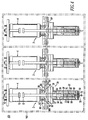
- Figure 4 shows a three-phase, spring-loaded, high-speed vacuum shorting switch 101 employing three of the shorting switches 2 of Figure 1.
- the three first terminals 16 of the three shorting switches 2 may be respectively electrically connected with three corresponding power busses ( e.g. , phases A, B and C).
- the three second terminals 22 of the three shorting switches 2 may be electrically connected to a common ground bus (not shown) by the common flexible shunt 99'.
- the three-phase shorting switch 101 may employ, for example, a conventional molded housing 102 without an operating mechanism.
- the closing times of the shorting switches 2 of Figure 1 depend upon the amount of mass being moved and on the force applied by the compression springs 40.
- the exemplary shorting switches 2,101 are capable of being activated in the presence of an arcing fault in medium voltage switchgear and are able to maintain contact closure under medium voltage operating circuit parameters (e.g., 15 kV RMS at 38 KA RMS ).
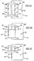
- the sensor unit 103 includes the first photovoltaic device 104 including at least one, or a plurality of series connected photovoltaic cells 105, and a first filter 107 which filters light incident upon the photovoltaic cells 105.
- This first filter 107 has a passband centered on the characteristic wavelength, e.g. , 521.820 nm, of the arcing material.
- the sensor 103 includes a second photovoltaic device 109, which also includes one or more series connected photovoltaic cells 111, and a second filter 113 which filters light incident upon the photovoltaic cells 111 and has a passband that does not include the characteristic wavelength of the arcing material, e.g. , centered on about 600 nm in the exemplary system.
- the first photovoltaic device 104 generates a sensed light electrical signal in response to the filtered incident light, and similarly, the second photovoltaic device 109 generates a background light electrical signal with an amplitude dependent upon the irradiance of light in the passband of the second filter 113.
- An electric circuit 115 having a first branch 115 1 connecting the first photovoltaic cells 104 in series and a second branch 115 2 similarly connecting the second photovoltaic cells 111 in series, connects these two electrical signals in opposition to a light-emitting device such as a light-emitting diode (LED) 117.
- a light-emitting device such as a light-emitting diode (LED)
- the sensed light electrical signal generated by the first photovoltaic device 104 exceeds the background light electrical signal generated by the second photovoltaic device 109 by a threshold amount sufficient to turn on the LED 117. While in the absence of arcing, the first photovoltaic device 104 will generate a sensed light electrical signal due to some irradiance in the passband of the first filter 107, it will be insufficient to overcome the reverse bias effect of the background light signal generated by the second photovoltaic device 109 on the LED 117.
- the background light is fluorescent
- an incandescent bulb or a flashlight all of which have very low irradiance in the passband of the first filter 107, but significant irradiance in the passband of the second filter 113
- the background light electrical signal will significantly exceed the sensed light electrical signal and strongly reverse bias the LED 117.
- the filters 107 and 113 can be interference filters, although lower cost bandpass filters could also be utilized.
- An alternate embodiment of the sensor unit 103' shown in Figure 5B adds a bias generator 119 in the form of one or more additional photovoltaic cells 121 connected in series with the first photovoltaic device 104 in the first branch 115 1 of the electrical circuit 115.
- This puts a forward bias on the LED 117 so that fewer or smaller filtered photovoltaic cells 105 and 111 can be used. This also reduces the size and therefore the cost of the filters 107 and 113.
- the additional photovoltaic cells 121 are not provided with filters, the total cost of the sensor is reduced.
- the embodiment of Figure 5B can be modified as shown in Figure 5C to place the bias generating cells 121 of the sensor 103" in series with both filtered photovoltaic cells 105 and 111, but still provide the same effect of forward biasing the LED 117.
- the circuit 146 includes a detection (OD) circuit 148 for detecting the arcing fault 142 and responsively outputting one or more trigger signals 150, and an activation circuit (ACT) 152 for detecting the one or more trigger signals 150 and responsively outputting the activation signal 154 to the electrical inputs 155 of the charges 60.
- the detection circuit 148 utilizes photovoltaic cells in a sensor unit, such as one of the sensor units 103,103',103" of Figures 5A-5C.
- the window of the sensor unit is blocked to prevent arc light from reaching the detector, which is aimed at the arc-viewing window.
- a circuit breaker (not shown) arcs phase-to-phase on the line side and the sensor unit detects this.
- the sensor did not respond to the arc through the window in the circuit breaker since the light was blocked. But, since the breaker arced phase-to-phase, externally, the arc light was subsequently detected, albeit at a later time (4.4 ms total response time versus 3.20 ms).
- the shorting switch 2 responsively quenches the arcing fault, thereby saving the circuit breaker.
- Figure 7C shows a plot of bus voltage and current over 27 cycles at 500V and 38 kA on a shorting switch, similar to the shorting switch for Figures 7A and 7B, except that symmetric length movable and stationary electrical stems are employed in the vacuum interrupter.
- the window of the sensor unit is darkened.
- the sensor response time is longer (0.82 ms versus 0.60 ms) and the total response time is less than the response time for Figures 7A and 7B since a smaller moving mass is employed.
- the exemplary spring-loaded vacuum shorting switch 2 successfully operates within about 3.2 ms (Figure 7A), including sensing time, and holds closed for 27 cycles at 38 kA RMS ( Figures 7B and 7C). As shown by Table 1, the shorting switches, switch, after triggenng, between about 2.06 ms and about 2.84 ms and each one remains closed for the duration of the fault current.
- the medium voltage power distribution equipment 144 of Figure 7 includes two circuit breaker cells 156,157, two upper cable cells 158,159, and two lower cable cells 160,161, although the invention is applicable to a wide range of medium voltage power distribution equipment having any count ( e.g. , one or more) of cells in which an arcing fault may occur.
- U.S. Patent No. 6,229,680 which is incorporated by reference herein, discloses a switchgear cabinet having a forward compartment, a middle compartment and a rear compartment. The forward compartment is divided vertically into three cells in which are housed electrical switching apparatus such as circuit breakers.
- the detection circuit 148 includes six photovoltaic sensors 162,164, 166,168,170,172 adapted to detect arcing faults in the cells 156,158,160,157,159,161, and output optical trigger signals 174,176,178,180,182,184, respectively.
- These photovoltaic sensors 162,164,166,168,170,172 are self-powered from arc light and have an output 186 (as shown with sensor 162) with the respective optical trigger signals 174,176,178,180,182,184, which are responsive to the arc light.
- suitable photovoltaic sensors are shown in Figures 5A-5C, although any suitable sensor for detecting any characteristic of an arcing fault may be employed.
- the detection circuit 148 is employed for each switchgear enclosure (not shown), with three photovoltaic sensors for each circuit breaker cell.
- the detection circuit 148 further includes a suitable optical multiplexer 188 having a plurality of fiber optic inputs 190,192,194,196,198,200 and a fiber optic output 202.
- a plurality of suitable fiber optic cables 204,206,208,210,212,214 are connected between the outputs 186 of the photovoltaic sensors 162,164,166,168,170,172 and the inputs 190,192,194,196,198,200, respectively, of the optical multiplexer 188.
- the fiber optic cables (as shown with cable 210) include a first connector 216 attached to the corresponding photovoltaic sensor output (as shown with the output 186 of sensor 168) and a second connector 218 attached to the corresponding optical multiplexer input (as shown with input 196).
- the output 202 of the optical multiplexer 188 outputs an optical trigger signal 220 to another fiber optic cable 222, which includes a first connector 224 attached to the multiplexer output 202.
- the other end (as shown in Figure 9A) of fiber optic cable 222 includes a second connector 226, which is attached to the activation circuit 152.
- the optical multiplexer 188 functions to repeat any of the first optical trigger signals 174,176,178,180,182,184 to the second optical trigger signal 220.
- the detection circuit 148 further includes a suitable power supply, which in the exemplary embodiment is an AC/DC power supply 228, which inputs an AC line voltage 230 and outputs a suitable DC voltage 240 to the optical multiplexer 188 at node 241.
- a suitable power supply which in the exemplary embodiment is an AC/DC power supply 228, which inputs an AC line voltage 230 and outputs a suitable DC voltage 240 to the optical multiplexer 188 at node 241.
- the optical multiplexer 188 has an electrical output 242, which is electrically connected to the gate of transistor 244 through resistor 261.
- the other five multiplexer inputs 192,190,196,198,200 have similar outputs 242B,242C,242D,242E,242F, respectively.
- the emitter of the transistor 244 is electrically connected to the common 246 of the power supply 228, and the collector of the transistor 244 is electrically connected through a resistor 248 to the cathode of an output photodiode 250 of the optical multiplexer 188.
- the anode of the photodiode 250 and the collectors of the input phototransistors 251A-251F (e.g. , similar to the phototransistor 408 of Figure 9A) of the optical multiplexer 188 are electrically connected to the DC voltage node 241.
- a resistor 252 is electrically connected between the gate and emitter of the transistor 244.
- a zener diode 254 is electrically connected in parallel with the resistor 252.
- the detection circuit 148 preferably includes a plurality of suitable indication circuits, such as 258 for multiplexer input A, having an input 259 and one or more indication outputs 260 for indicating the occurrence of an arc fault trigger event as determined by a suitable voltage at the optical multiplexer output 242 as measured across resistors 261 and 252.
- Other circuits 258 are provided for the other multiplexer inputs, which have resistors 261B, 261C, 26 1 D, 26 1 E, 261 F electrically connected between the respective outputs 242B, 242C, 242D, 242E, 242F and the gate of transistor 244.
- the flip-flop (FF) 262 has a reset state, which is established by pushbutton 264.
- a green LED 272 is extinguished, and a red LED 274 is illuminated.
- the flip-flop outputs 268,270 change state, again, with the red LED 274 being extinguished and the green LED 272 being illuminated.
- Figures 9A-9B show the activation circuit 152 of Figure 7, which detects one or more of the trigger signals, such as the optical trigger signal 220 of Figure 8, and responsively outputs the activation signal 154 to the electrical inputs 155 of the charges 60.
- the activation circuit 152 is employed with a three-phase circuit breaker (not shown) having a pair of charges 60 for each of the shorting switches 2 for each of the three phases A,B,C, although the invention is applicable to any count of shorting switches 2 ( e.g., one or more), any count of phases ( e.g., one, two, three or more), any count of shorting switches per phase ( e.g. , one, two, or more), and any count of charges ( e.g., one or more) per shorting switch.
- the activation circuit 152 includes a suitable high voltage power supply 280 ( Figures 9B-9C), which generates a suitable charge voltage 282 (e.g. , without limitation, 2000 VDC) between nodes 284,286 from an input voltage 288 (e.g. , without limitation, 120 VAC RMS ).
- a triggerable spark gap 290 such as a model GP-486 marketed by Perkin Elmer of Salem, Massachusetts, has an input 292 electrically connected to the node 284, an output 294 electrically connected to a first input 296 of the charges 60, and a trigger control input 298.
- the other node 286 is electrically connected to the second input 300 of the charges 60.
- the spark gap 290 presents an open circuit between the input 292 and output 294.
- the spark gap 290 becomes a short circuit, thereby electrically connecting the node 284 to the first charge input 296 and, thus, electrically connecting the charge voltage 282 to the charge electrical inputs 155.
- a circuit 302 detects the one or more trigger signals 220 and responsively outputs a control signal 304 (with respect to the node 286) to the control input 298 of the spark gap 290. As discussed above, in responsive to the control signal 304, the spark gap 290 outputs the activation signal 154 to the electrical inputs 155 of the charges 60.
- the circuit 302 which is preferably housed in a suitable EMI / magnetic shield (not shown), includes one or more circuits 306,306A,306B for detecting the one or more trigger signals 220 (only one trigger signal is shown), respectively.
- a suitable EMI / magnetic shield includes one or more circuits 306,306A,306B for detecting the one or more trigger signals 220 (only one trigger signal is shown), respectively.
- zero, one or more (e.g. , 306A,306B) additional circuits may be employed in the event that the medium voltage power distribution equipment (e.g., 144 of Figure 7) includes more than six exemplary arc fault detection locations.
- the circuits 306,306A,306B include a common output 308 having a detected trigger signal 310.
- a circuit 312 has an input 314, which is electrically connected to the common output 308 of the circuits 306,306A,306B.
- the circuit 312 outputs the control signal 304 responsive to the detected trigger signal 310.
- the power supply 280 of Figure 9B includes a line-conditioning filter 316, an MOV 318, a fuse 320, a transformer 322, a full wave bridge 324, a capacitor 326 and a DC/DC regulator (REG) 332.
- the power supply 280 functions to output a suitable DC voltage 338 (e.g., + 17 VDC) between power supply node 340 and common node 342.
- the DC/DC regulator 338 outputs a suitable DC voltage 346 (e.g., + 12 VDC) to a suitable high voltage DC/DC regulator 348 of Figure 9C.
- the regulator 348 generates the charge voltage 282 between the nodes 284,286.
- the series combination of a resistor 350 and an LED 352 is electrically connected in parallel with the capacitor 326 to indicate the DC voltage 338 and the test mode as selected by the closed state of the contact 334.
- a suitable switch 354 is provided with the normally open (NO) contacts 334,336 and a suitable normally closed (NC) contact 358 (e.g. , one NC contact or plural NC contacts electrically connected in series).
- the switch 354 preferably includes a key (not shown), which key has three positions, including a first off position 364, a second test position 366, and a third arm position 368, and is removable in the off and arm positions 364,368.
- the states of the contacts 334,336,358 are static in each of the three key positions 364,366,368.
- the NO contacts 334,336 are open, thereby disabling the power supply 280, the regulators 332,348 and the circuit 302, and the NC contact 358 is closed, thereby ensuring that the activation signal 154 is suitably electrically connected to the common node 286.
- the NO contact 334 is closed, thereby enabling the DC voltage 338 (e.g., + 17 VDC) at the power supply node 340, and the circuit 302.
- the regulators 332,348 remain disabled.
- the NC contact 358 is opened and, then, the NO contact 336 is closed. This safely removes the short circuit between the nodes 296,286 before the regulators 332,348 are enabled.
- the circuit 306 preferably includes a suitable indication circuit 369, which is similar to the indication circuit 258 of Figure 8.
- the circuit 369 has one or more indication outputs 370 for indicating that the trigger signal 220 has been received as determined by a suitable voltage at the node 410.
- the flip-flop 372 has a reset state, which is established by pushbutton 374. Otherwise, in response to the trigger signal 220, the voltage 409, as buffered by operational amplifier 376, causes the flip-flop outputs 378,380 to change state. In response, a green LED 382 is extinguished, and a red LED 384 is illuminated. Following manual operation of the pushbutton 374, the flip-flop outputs 378,380 change state, again, with the red LED 384 being extinguished and the green LED 382 being illuminated.
- the circuit 302 includes a pair of power supplies 386,388, both of which are powered from nodes 390 and 392 of the power supply 280.
- the circuit 302 also includes a filter bushing 394, which further filters the switched line voltage between the nodes 390,392, and a fuse 396.
- the first power supply 386 has an output 398 with a suitable unregulated DC voltage 399 (e.g., + 170 VDC) with respect to a ground node 400.
- the voltage 399 powers a portion of the circuit 312.
- the second power supply 388 has an output 402 with a suitable unregulated DC voltage 403 (e.g. , + 24 VDC) with respect to the ground node 400.
- the voltage 403 powers a DC/DC regulator 405, which has an output 406 with a suitable regulated DC voltage 407 (e.g. , + 15 VDC) with respect to the ground node 400.
- the voltage 407 powers the circuits 306,306A,306B.
- the circuits 306,306A,306B detect the one or more optical trigger signals 220 (as shown with circuit 306) and have a common output 308 with the detected trigger signal 310.
- the circuit 306 includes a suitable phototransistor 408, which in the exemplary embodiment is a model OP802WSL marketed by Honeywell of Morristown, New Jersey, although any suitable phototransistor for optical signals may be employed.
- the phototransistor 408 Whenever the optical trigger signal 220 is active, the phototransistor 408 generates a corresponding voltage 409 at output 410 by sourcing current through resistor 412 to the ground node 400.
- the voltage 409 is buffered by the non-inverting (+) input of operational amplifier 414, which provides the corresponding detected trigger signal 310 at the common output 308.
- the phototransistor 408 and the operational amplifier 414 are both powered from the power supply output 406 having the regulated DC voltage 407.
- the circuits 306A and 306B are similar to the circuit 306.
- the multivibrator 416 In response to the rising edge of the detected trigger signal 310, as detected at input 423, the multivibrator 416 provides a suitable pulse at output 424, which is connected by line 425 to the gate of the transistor 418.
- the transistor 418 turns on, thereby effectively electrically connecting the collector side of resistor 419 to the ground node 400.
- the step change in voltage (e.g. , about -170 VDC) on the transformer side of capacitor 420 is communicated to the primary winding 426 of the transformer 422.
- the transformer (inverted) secondary winding 428 provides a suitable positive voltage pulse, which is the control signal 304, to twisted pair conductors 430, which are electrically connected to the control input 298 of the spark gap 290 and the second input 300 of the charges 60.
- the circuits 306,312 of the activation circuit 152 provide a minimal delay ( e.g. , without limitation, about 40 ⁇ s) between the activation of the optical trigger signal 220 and the activation of the control signal 304.
- the circuit 302 includes a circuit 432 for tripping an upstream circuit breaker (not shown) in response to the detected trigger signal 310 and the output pulse of the multivibrator output 424.
- the circuit 432 includes a transistor 434 and a relay 436 having a coil 438 and contacts 440.
- the power supply 386 includes the series combination of a resistor 442 and a capacitor 444, which combination is electrically connected between the nodes 398,400.
- the common node 446 of the resistor-capacitor combination sources a suitable voltage 448 (e.g. , about +170 VDC) to one side of the relay coil 438.
- the other side of the relay coil 438 is switched by the transistor 434 to the ground node 400 in response to the output pulse of the multivibrator output 424.
- the normally open (NO) contacts 440 are closed.
- the contacts 440 are electrically connected to terminals 450,452, which are adapted for electrical connection to the upstream circuit breaker by a suitable cable (not shown).
- the circuits 306,312,432 of the activation circuit 152 provide a suitable delay (e.g. , without limitation, about 6 to 10 ms) between the activation of the optical trigger signal 220 and the closure of the NO contacts 440.
- a suitable delay e.g. , without limitation, about 6 to 10 ms
- the activation circuit 152 includes an output relay and contact (not shown) which is employed to enable an upstream circuit breaker (not shown) for the medium voltage power distribution equipment 144 of Figure 7.
- the activation circuit 152 preferably further includes an annunciator circuit (not shown) which annunciates when such upstream circuit breaker is not enabled.
- such upstream circuit breaker is enabled whenever the various power supply voltages (e.g. , +12 VDC, +17 VDC, +170 VDC, +2000 VDC) of the activation circuit 152 are suitably energized.
- FIG 10 shows a single phase, spring-loaded, high-speed vacuum shorting switch 502 employing the conventional vacuum interrupter (VI) 4 of Figure 1 and a ball-lock mechanism 504.
- the switch 502 includes a driven member 506 having a longitudinal opening 508 with a circumferential groove 510 therein.
- a suitable mount 512 which includes a frame 514 and a spring cover tube 516, mounts the driven member 506 for linear movement along a path substantially parallel to the longitudinal axis of the movable contact assembly 10.
- the driven member 506 is suitably coupled (e.g.
- a suitable spring member such as compression spring 520, has a compressed state (as shown in Figure 10) and a released state (as shown in Figure 11D), which moves the driven member 506 and the movable contact assembly 10 to the closed circuit position.
- the ball-lock mechanism 504 has a plurality of ball bearings, such as 522,524, and a push rod 526 with a circumferential groove 528 therein.
- the ball bearings 522,524 normally engage the circumferential groove 510 of the longitudinal opening 508 of the driven member 506 to hold the spring member 520 in the compressed state between a flange portion 530 of the ball-lock mechanism 504 and a flange portion 532 of the driven member 506. This, also, holds the movable contact assembly 10 in the open circuit position of Figure 10.
- a suitable electro-mechanical mechanism such as a solenoid 534, includes a plunger 536 for driving the ball-lock push rod 526 into the longitudinal opening 508 of the driven member 506 to cause the ball bearings 522,524 to engage the circumferential groove 528 of the ball-lock push rod 526 and to release the driven member 506, in order to move the movable contact assembly 10 to the closed circuit position.
- the solenoid plunger 536 drives (as shown in Figures 11B and 11C) the ball-lock push rod 526 into the driven member longitudinal opening 508.
- the longitudinal spring tube 516 has a first end 542 and a second end 544 and houses the compression spring 520 and the ball-lock mechanism 504.
- the first spring end 546 engages the flange portion 530 of the ball-lock mechanism 504, which is suitably coupled to the first tube end 542.
- the frame 514 has an opening 548 at the second tube end 544 with the upper (with respect to Figure 10) end portion 550 of the driven member 506 passing through such opening. Whenever the ball-lock mechanism 504 releases the driven member 506, the second spring end 552 suitably biases the driven member 506 to move the movable contact assembly 10 to the closed circuit position.
- the first VI terminal 16 is adapted for electrical connection ( e.g. , through a suitable conductive fastener 554) to a first power line, such as power bus 78, and the second VI terminal 22 is adapted for electrical connection to a suitable flexible shunt 556 ( e.g. , copper laminate).
- a suitable flexible shunt 556 e.g. , copper laminate.
- the driven member 506 and the movable contact assembly 10 are free to move independent of a rigid second power line 558 (e.g. , ground or neutral bus).
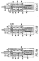
- Figure 11A shows the locked position of the ball-lock mechanism 504 with the solenoid plunger 536 stationary, the ball bearings 522,524 in the circumferential groove 510, and the separable contacts 12,18 of Figure 10 being open.
- the ball-lock push rod 526 passes through an opening 560 in the flange portion 530 of the ball-lock mechanism 504 for engagement by the solenoid plunger 536 as shown in Figures 11B-11D.
- the solenoid coil 540 remains energized, the actuated solenoid plunger 536 continues to drive the ball-lock push rod 526, thereby causing the ball bearings 522,524 to roll down into the push rod circumferential groove 522 and releasing the driven member 506, although the separable contacts 12,18 of Figure 10 remain open.
- the actuated solenoid plunger 536 strikes the push rod 526 causing the ball bearings 522,524 to enter the circumferential groove 522, thereby releasing the driven member 506 and the compression spring 520.
- the ball-lock mechanism 504 is shown in Figures 10 and 11A-11D, any suitable ball-lock configuration may be employed.
- the ball-lock mechanism 504 includes a headed shank 564 having a central through-bore 566.
- An end of the shank 564 opposite the head has a pair of radially opposite passageways 568, which extend radially outward from the central through-bore 566.
- the passageways 568 are formed with a constant diameter bore and receive a similarly sized one of the ball bearings 522,524.
- the ball bearings 522,524 are inserted into the corresponding passageway 568 and the outer edge of each such passageway is locally crimped.
- the push rod 526 is axially retained in the position of Figure 11A by the solenoid plunger 536.
- the radially inward extending circumferential groove 522 allows the ball bearings 522,524 to be radially inwardly displaced by axially displacing the push rod 526 with the solenoid plunger 536 as shown in Figures 11B and 11C in order to center the groove 522 beneath the pair of ball bearings 522,524 ( Figure 11C).
- Figure 12 shows a single phase, spring-loaded, high-speed vacuum shorting switch 602 employing the conventional vacuum interrupter (VI) 4 of Figure 1, a spring member such as compression spring 604, a mechanical latch release mechanism 605, and an electro-mechanical mechanism such as solenoid 606.
- VI vacuum interrupter
- a driven member 608 includes a circular flange portion 610, an upper shaft portion 612 and a coupler 614.
- the upper shaft portion 612 is suitably secured (e.g., by welding) to the circular flange portion 610.
- the coupler 614 is suitably secured ( e.g. , threadably connected) to both the driven member 608 and the terminal 22 of the movable contact assembly 10 to move such assembly between the open circuit position and the closed circuit position with the linear movement of the driven member 608.
- a suitable mount 616 which includes the frame 514 of Figure 10 and a spring tube 617, mounts the driven member 608 and, thus, the second terminal 22 with respect to a housing 618 for linear movement along a path substantially parallel to the longitudinal axis of the movable contact assembly 10.
- the compression spring 604 is disposed within the spring tube 617 with the circular flange portion 610 at one end and a surface 620 of the housing 618 at the other end.
- the compression spring 604 has a compressed state (as shown in Figure 12) and a released state (not shown), which moves the driven member 608 and the movable contact assembly 10 to the closed circuit position (not shown).
- the mechanical latch release mechanism 605 includes a latch member, such as lower shaft portion 622, having an upper hook portion 624, which normally latches a corresponding lower hook portion 626 of the upper shaft portion 612 of the driven member 608. This holds the compression spring 604 in the compressed state and holds the movable contact assembly 10 in the open circuit position. Otherwise, the lower shaft portion 622 releases the upper shaft portion 612 in order to release the driven member 608 to move the movable contact assembly 10 to the closed circuit position.
- a latch member such as lower shaft portion 622, having an upper hook portion 624, which normally latches a corresponding lower hook portion 626 of the upper shaft portion 612 of the driven member 608.
- the lower shaft portion 622 includes a central opening 627 and a lower pin 628.
- a spring 630 (e.g. , about three pounds) is connected between the upper hook portion 624 and a surface 632 of the housing 618 in order to bias the lower shaft portion 622 clockwise with respect to Figure 12 and, thereby, suitably engage the corresponding hook portions 624,626.
- the solenoid 606 has a normally extended plunger 634 and coil 636. Whenever the solenoid 606 is activated by a suitable activation signal on leads 637, which energizes the solenoid coil 636, such solenoid retracts the plunger 634 ( e.g. , toward the right of Figure 12).
- the plunger 634 has an opening 638, which captures therein the pin 628 of the lower shaft portion 622.
- a plunger end portion 639 engages the pin 628, which rotates the lower shaft portion 622 counterclockwise about pivot point 640 of the housing 618 against the bias of the spring 630.
- the upper hook portion 624 of the lower shaft portion 622 unlatches the lower hook portion 626 of the upper shaft portion 612, thereby releasing the driven member 608.
- the compression spring 604 drives the driven member 608 upward (with respect to Figure 12) in order to close the separable contacts 12,18 of the shorting switch 602.
- the first terminal 16 is adapted for electrical connection to a power line, such as 78
- the second terminal 22 is adapted for electrical connection to a flexible conductor, such as 556.
- the shorting switch 502 of Figure 10 and the shorting switch 602 of Figure 12 are operable with a detection and activation circuit, which is similar to the circuit 146 of Figures 6, 8 and 9A-9B.
- That circuit 146 includes the detection (OD) circuit 148 of Figure 8, which detects the arcing fault 142 and responsively outputs one or more trigger signals 150, and the activation circuit (ACT) 152 of Figures 9A-9C, which detects the one or more trigger signals 150 and responsively outputs the activation signal 154.
- the shorting switches 502,602 employs the respective solenoids 534,606, rather than the charges 60.
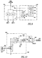
- Figure 13 shows a suitable circuit 641 for driving either of the solenoids 534,606 from the output 424 of the one-shot multivibrator 416 of Figure 9A.
- the multivibrator output 424 provides a pulse of suitable duration (e.g., about 1.2 ⁇ s).
- the circuit 642 triggers a thyristor 644, which causes a capacitor (C) 646 to dump current into the solenoid coil 648 ( e.g. , coil 540 of Figure 10 or coil 636 of Figure 12).
- Lc + Lstray The value of L in Table 2 is defined by Lc + Lstray.
- Figures 14A-14C show plots of the solenoid gap (g), force of the plunger 650, and current of the coil 648, respectively, for analyzing the motion of the solenoids 534,606.
- the exemplary shorting switches 2,101,502,602 employ relatively simple and low cost approaches in providing an energy storage and release mechanism.
- the compression springs 40,520,604 provide a suitable closing and holding force on the vacuum interrupter (VI) 4 or a modified VI (e.g. , no shield; no contacts or modified contacts) (not shown) for use with medium voltage power distribution equipment, such as switchgear.
Landscapes
- Driving Mechanisms And Operating Circuits Of Arc-Extinguishing High-Tension Switches (AREA)
- Arc-Extinguishing Devices That Are Switches (AREA)
Claims (30)
- Ein Kurzschlussschalter (2) zum Eliminieren von Lichtbogenfehlern in Leistungsversorgungsausrüstung (144), wobei der Kurzschlussschalter (2) folgendes aufweist:Einen Vakuumschalter (4), welcher eine Vakuumhülle (6) aufweist, welche eine feste Kontaktanordnung (8) und eine bewegliche Kontaktanordnung (10) enthält, welche entlang einer Längsachse zwischen einer Position des geschlossenen Stromkreises in elektrischem Kontakt mit der festen Kontaktanordnung und einer Position mit offenem Stromkreis bewegbar ist, welche von der festen Kontaktanordnung beabstandet ist;erste und zweite Anschlüsse (16, 22), welche jeweils elektrisch verbunden sind mit der festen Kontaktanordnung (8) und der beweglichen Kontaktanordnung (10); ein angetriebenes Glied (26);eine Halterung (34), welche das angetriebene Glied (26) für lineare Bewegung entlang eines Pfades, welcher im wesentlichen parallel zu der Längsachse der beweglichen Kontaktanordnung (10) ist, hält, wobei das bewegbare Glied (26) mit der beweglichen Kontaktanordnung (10) gekuppelt ist, um die bewegliche Kontaktanordnung zwischen der Position des offenen Stromkreises und der Position des geschlossenen Stromkreises mit der linearen Bewegung des angetriebenen Glieds (26) zu bewegen;ein Federglied (40), welches einen komprimierten Zustand und einen freigegebenen Zustand hat, welches das angetriebene Glied (26) und die Vorrichtung (10) mit bewegbarem Kontakt in die Position des geschlossenen Schaltkreises bewegt, dadurch gekennzeichnet, dass der Schalter (2) ferner folgendes aufweist:ein Freigabeglied (32), welches eine Öffnung (68) darin hat, wobei das Freigabeglied (32) mit dem angetriebenen Glied (26) gekuppelt ist und normalerweise das Federglied (40) in dem komprimierten Zustand hält;eine Ladung (60), welche in der Öffnung (68) des Freigabeglieds (32) angeordnet ist, wobei die Ladung (60) betätigt wird, um das Freigabeglied (32) zu brechen und das Federglied (40) zu dem freigegebenen Zustand freizugeben.
- Der Kurzschlussschalter (2) gemäß Anspruch 1, wobei die Vakuumhülle (6) eine abgedichtete Vakuumkammer ist; wobei die feste Kontaktanordnung (8) einen festen Kontakt (12) aufweist, welcher innerhalb der abgedichteten Vakuumkammer (6) abgedichtet ist, und einen elektrischen Leiter (14), welcher mit dem festen Kontakt an einem seiner Enden verbunden ist, wobei der elektrische Leiter in abgedichteter Weise in die abgedichtete Vakuumkammer eindringt und an dem ersten Anschluss (16) an dem anderen Ende des festen Kontakts endet;
wobei die bewegliche Kontaktanordnung (10) einen bewegbaren Kontakt (18) aufweist, welcher innerhalb der abgedichteten Vakuumkammer (6) abgedichtet und bewegbar ist, und zwar zwischen einer ersten Position heraus aus der elektrischen Verbindung mit dem festen Kontakt (12), und einer zweite Position in elektrischer Verbindung mit dem festen Kontakt, wobei die bewegliche Kontaktanordnung (10) ferner einen elektrischen Stab (20) aufweist, welcher mit dem bewegbaren Kontakt (18) an einem seiner Enden verbunden ist, wobei der elektrische Stab abgedichtet in die abgedichtete Vakuumkammer (6) eindringt, und an dem zweiten Anschluss (22) an dem anderen Ende des bewegbaren Kontakts aufhört; und wobei das bewegbare Glied (26) mit dem bewegbaren elektrischen Stab (20) verbunden ist. - Der Kurzschlussschalter (2) gemäß Anspruch 1, wobei das Federglied (40) eine Kompressionsfeder ist, welche ein erstes Ende und ein zweites Ende hat; wobei das Freigabeglied (32) ein Freigabebolzen ist, welcher ein erstes Ende und ein zweites Ende aufweist; und wobei der Halter (34) eine Buchse (36) aufweist, welche eine longitudinale Öffnung (66) aufweist, und ferner ein longitudinales Rohr (38), welches ein geschlossenes Ende (50) und ein offenes Ende (52) hat, wobei das longitudinale Rohr die Kompressionsfeder (40), den Freigabebolzen (32) und die Ladung (60) beinhaltet, wobei das erste Ende der Kompressionsfeder mit dem geschlossenen Ende des longitudinalen Rohrs in Eingriff kommt, das erste Ende des Freigabebolzens mit dem geschlossenen Ende des longitudinalen Rohrs gekuppelt ist, das erste Ende des bewegbaren Glieds mit dem zweiten Ende des Freigabebolzens gekuppelt ist, die Buchse in dem offenen Ende des longitudinalen Rohrs gelagert ist, das angetriebene Glied in der longitudinalen Öffnung der Buchse gelagert ist, das zweite Ende der Kompressionsfeder das bewegbare Glied (26) vorspannt, um die bewegliche Kontaktanordnung (10) in die Position des geschlossenen Stromkreises nach Betätigung der Ladung zu bewegen.
- Der Kurzschlussschalter (2) gemäß Anspruch 1, wobei die Ladung (60) eine elektrisch aktivierte chemische Ladung (60) ist.
- Der Kurzschlussschalter (2) gemäß Anspruch 1, wobei die ersten und zweiten Anschlüsse (16, 22) jeweils zur elektrischen Verbindung mit ersten und zweiten Leistungsleitungen (78, 80) verbunden sind.
- Der Kurzschlussschalter (2) gemäß Anspruch 1, wobei der erste Anschluss (16) für elektrische Verbindung mit einer Leistungsleitung (78) angepasst ist; und wobei der zweite Anschluss (22) zur elektrischen Verbindung mit einem flexiblen Leiter (99) angepasst ist.
- Der Kurzschlussschalter (2) gemäß Anspruch 1, wobei die ersten und zweiten Anschlüsse (16, 22) zur elektrischen Verbindung mit einer Leistungsleitung (78) und einem Nulleiter oder einer Erde (18) angepasst sind.
- Der Kurzschlussschalter (2) gemäß Anspruch 1, wobei das Freigabeglied (32) eine Längsachse hat; und wobei die Öffnung (68) des Freigabeglieds (32) ein longitudinaler Hohlraum (68) entlang der Längsachse des Freigabeglieds (32) ist.
- Der Kurzschlussschalter (2) gemäß Anspruch 8, wobei die Ladung (60) aktiviert wird, um eine Schockwelle vorzusehen, um das Freigabeglied (32) zu brechen; und wobei das Freigabeglied (32) ein Freigabebolzen (32) ist, welcher einen Körper (70) und eine Bruchlinie (72) aufweist, welche darauf angeordnet ist, um den Bruch des Freigabebolzens (32) ansprechend auf die Schockwelle zu lokalisieren und zu kontrollieren.
- Der Kurzschlussschalter (2) gemäß Anspruch 8, wobei die Bruchlinie (72) eine vorbestimmte Tiefe in dem Körper (70) des Freigabebolzens (32) hat; und wobei das Freigabeglied (40) eine vorbestimmte Kompressionskraft hat, wobei der Freigabebolzen (32) derart strukturiert ist, um mindestens die Kompressionskraft zu halten, bis die Ladung (60) aktiviert wird.
- Ein Kurzschlusssystem (140) zum Eliminieren von Lichtbogenfehlern (142) in Leistungsverteilungsausrüstung (144), wobei das Kurzschlusssystem (140) folgendes aufweist:Den Kurzschlussschalter (2) gemäß Anspruch 1, dadurch gekennzeichnet dass das Kurzschlusssystem (140) ferner folgendes aufweist:wobei die aktivierte Ladung (60) das Freigabeglied (32) bricht, welches das Federglied (40) freigibt, welches das angegebene Glied (26) antreibt, um die bewegliche Kontaktanordnung (10) in die Position des geschlossenen Stromkreises zu bewegen, um den Lichtbogenfehler zu eliminieren.Mittel (146) zum Detektieren eines Lichtbogenfehlers und darauf ansprechende Aktivierung der Ladung (60), welche in der Öffnung (68) des Freigabegliedes (32) angeordnet ist,
- Das Kurzschlusssystem (140) gemäß Anspruch 11, wobei die Ladung (60) einen elektrischen Eingang (155) aufweist; und wobei die Mittel (146) zum Detektieren eines Lichtbogenfehlers und darauf ansprechende Aktivierung der Ladung (60) Mittel (148) zum Detektieren des Lichtbogenfehlers (142) und darauf ansprechende Ausgabe eines Triggersignals (150, 220) und Mittel (152) zum Detektieren des Triggersignals (150, 220) und darauf ansprechende Ausgabe eines Aktivierungssignals (154) zu dem elektrischen Eingang (155) der Ladung (60) aufweist.
- Das Kurzschlusssystem (140) gemäß Anspruch 12, wobei die Ladung (60) eine elektrisch aktivierte chemische Ladung (60) ist.
- Das Kurzschlusssystem (140) gemäß Anspruch 11, wobei der Vakuumschalter (4) angepasst ist zum Betrieb mit Leistungsverteilungsausrüstung (144) für mittlere Spannung.
- Das Kurzschlusssystem (140) gemäß Anspruch 11, wobei die Mittel (146) zum Detektieren eines Lichtbogenfehlers und darauf ansprechende Aktivierung der Ladung (60) eine Aktivierungsverzögerung von ungefähr 550 µs nach der Initiierung eines Lichtbogenfehlerereignisses aufweist.
- Das Kurzschlusssystem (140) gemäß Anspruch 12, wobei die Mittel (148) zum Detektieren des Lichtbogenfehlers und darauf ansprechende Ausgabe eines Triggersignals (150, 220) mindestens einen photovoltaischen Sensor (162, 164, 166, 168, 170, 172) aufweisen, welcher angepasst ist zum Detektieren eines Lichtbogenfehlers und zur Ausgabe eines optischen Signals (174) als das Triggersignal (220).
- Das Kurzschlusssystem (140) gemäß Anspruch 16, wobei der Lichtbogenfehler Bogenlicht aufweist; und wobei der mindestens eine photovoltaische Sensor (162, 164, 166, 168, 170, 172) ein photovoltaischer Sensor ist, welcher selbstbetrieben ist von dem Bogenlicht, wobei der photovoltaische Sensor einen Ausgang (168) mit dem Triggersignal hat, welcher ansprechend auf das Bogenlicht ist.
- Das Kurzschlusssystem (140) gemäß Anspruch 12, wobei die Mittel (148) zum Detektieren des Lichtbogenfehlers und darauf ansprechende Ausgabe eines Triggersignals (150, 220) eine Vielzahl von photovoltaischen Sensoren (162, 164, 166, 168, 170, 172) aufweisen, wenn die angepasst sind zum Detektieren des Lichtbogenfehlers und zur Ausgabe einer Vielzahl von ersten optischen Signalen (174, 176, 178, 180, 182, 184) an einer Vielzahl von Ausgängen (186), einen optischen Multiplexer (188), welcher eine Vielzahl von Eingängen (190, 192, 194, 196, 198, 200) und einen Ausgang (202) besitzt, eine Vielzahl von faseroptischen Kabeln (204, 206, 208, 210, 212, 214), welche zwischen den Ausgängen (186) der photovoltaischen Sensoren (162, 164, 166, 168, 170, 172) und den Eingängen (190, 192, 194, 196, 198, 200) des optischen Multiplexers (188) verbunden sind, und wobei der Ausgang (202) des optischen Multiplexers (188) ein zweites optisches Signal (220) als das Triggersignal (220) ausgibt.
- Das Kurzschlusssystem (140) gemäß Anspruch 12, wobei die Mittel (152) zum Detektieren des Triggersignals (150, 220) und darauf ansprechende Ausgabe eines Aktivierungssignals (154) zu dem elektrischen Eingang (155) der Ladung (60) Mittel (280) zum Erzeugern einer Ladungsspannung (282), eine Funkenstrecke (290), welche angepasst ist, um die Ladungsspannung elektrisch zu dem elektrischen Eingang der Ladung zu verbinden, wobei die Funkenstrecke einen Steuerungseingang (298) besitzt, und Mittel (302) zum Detektieren des Triggersignals (220) und darauf ansprechende Ausgabe eines Steuerungssignals (304) zu dem Steuerungsseingang der Funkenstrecke aufweist, wobei die Funkenstrecke das Aktivierungssignal (154) zu dem elektrischen Eingang der Ladung ansprechend auf das Steuerungssignal (304) ausgibt.
- Das Kurzschlusssystem (140) gemäß Anspruch 19, wobei die Mittel (302) zum Detektieren des Triggersignals um darauf ansprechenden Ausgeben eines Steuerungssignals, Mittel (306) zum Detektieren des Triggersignals (220), und Mittel (312) zum Ausgeben des Steuerungssignals ansprechend auf das detektierte Triggersignal (310) aufweist.
- Das Kurzschlusssystem (140) gemäß Anspruch 20, wobei die Mittel (302) zum Detektieren des Triggersignals und darauf ansprechenden Ausgeben eines Steuerungssignals ferner Mittel (432) zum Auslösen eines stromaufwärts gelegenen Stromkreisunterbrechers für die Leistungsverteilungsausrüstung ansprechend auf das detektierte Triggersignal (310) aufweist.
- Das Kurzschlusssystem (140) gemäß Anspruch 12, wobei die Ladung (60) einen elektrischen Eingang (155) aufweist; und wobei die Mittel (146) zum Detektieren eines Lichtbogenfehlers und darauf ansprechende Aktivierung der Ladung (60) Mittel (148) zum Detektieren des Lichtbogenfehlers und darauf ansprechende Ausgabe einer Vielzahl von Triggersignalen (220) aufweisen, und Mittel (306, 306A, 306B, 312, 290) zum Detektieren der Triggersignale (220) und darauf ansprechenden Ausgeben eines Aktivierungssignals (154) zu dem elektrischen Eingang der Ladung.
- Ein Kurzschlussschalter (502) zum Eliminieren von Lichtbogenfehlern in Leistungsverteilungsausrüstung, wobei der Kurzschlussschalter (502) folgendes aufweist:Einen Vakuumschalter (4), welcher eine Vakuumhülle (6) aufweist, welche eine feste Kontaktanordnung (8) und eine bewegliche Kontaktanordnung (10) aufweist, welche entlang einer Längsachse zwischen einer Position des geschlossenen Stromkreises in elektrischem Kontakt mit der festen Kontaktanordnung und einer Position des offenen Stromkreises beabstandet von der festen Kontaktanordnung bewegbar ist;erste und zweite Anschlüsse (16, 22), welche jeweils elektrisch mit der Vorrichtung (8) mit festem Kontakt und der beweglichen Kontaktanordnung (10) verbunden sind;ein angetriebenes Glied (506), welches eine longitudinale Öffnung (508) mit einer umlaufenden Nut (510) darin aufweist;einen Halter (512) zum Halten des angetriebenen Gliedes (506) für lineare Bewegung entlang eine Pfades, welcher im wesentlichen parallel zu der Längsachse der beweglichen Kontaktanordnung (10) ist, wobei das angetriebene Glied mit der Anordnung mit bewegbarem Kontakt gekoppelt ist, um die bewegliche Kontaktanordnung zwischen der Position des offenen Stromkreises und der Position des geschlossenen Stromkreises mit der linearen Bewegung des angetriebenen Gliedes zu bewegen;Ein Federglied (520), welches einen komprimierten Zustand und einen freigegebenen Zustand hat, welches das angetriebene Glied (506) und die bewegliche Kontaktanordnung (10) zu der Position des geschlossenen Stromkreises bewegt; dadurch gekennzeichnet, dass der Schalter (502) ferner folgendes aufweist:ein Kugelverschlussglied (504), welches eine Vielzahl von Kugellagern (522, 524) und eine Schubstange (526) mit einer umlaufenden Nut (528) darin aufweist, wobei die Kugellager mit der umlaufenden Nut (510) der longitudinalen Öffnung (508) des angetriebenen Glieds (506) in Eingriff kommen, um das Federglied (520) in dem komprimierten Zustand zu halten, und um die Vorrichtung (10) mit bewegbarem Kontakt in der Position des geöffneten Schaltkreises zu halten;Mittel (534) zum Antreiben der Schubstange (526) des Kugelverschlussgliedes (504) in die longitudinale Öffnung (508) des angetriebenen Glieds (506), um zu erreichen, dass die Kugellager (522, 524) mit der umlaufenden Nut (528) der Schubstange (526) des Kugelverschlussglieds (504) in Eingriff kommen, und um das angetriebene Glied (506) freizugeben, um die bewegliche Kontaktanordnung (10) in die Position des geschlossenen Stromkreises zu bewegen.
- Der Kurzschlussschalter (502) gemäß Anspruch 23, wobei die Mittel (534) zum Antreiben der Drückstange ein Elektromagnet (534) sind, welcher einen Kolben (536) aufweist, welcher die Schubstange (526) des Kugelverschlussglieds (504) in die longitudinale Öffnung (508) des angetriebenen Glieds (506) treibt, wenn der Elektromagnet (534) betätigt wird.
- Der Kurzschlussschalter (502) gemäß Anspruch 23, wobei das Federglied (520) eine Kompressionsfeder (520) ist, welche ein erstes Ende (546) und ein zweites Ende (552) aufweist, wobei das Kugelverschlussglied (504) ein erstes Ende (530) und ein zweites Ende hat; wobei das angetriebene Glied (506) ein erstes Ende mit der longitudinalen Öffnung (508) und ein zweites Ende hat; und wobei der Halter (512) ein longitudinales Rohr (576) aufweist, welches ein erstes Ende (542) und ein offenes zweites Ende (544) aufweist, wobei das longitudinale Rohr (576) die Kompressionsfeder (520) und das Kugelverschlussglied (504) beinhaltet, wobei das erste Ende der Kompressionsfeder mit dem ersten Ende des longitudinalen Rohrs in Eingriff steht, wobei das erste Ende des Kugelverschlussglieds mit dem ersten Ende des longitudinalen Rohrs gekuppelt ist, wobei das zweite Ende des angetriebenen Glieds mit der beweglichen Kontaktanordnung gekuppelt ist, das erste Ende des angetriebenen Glieds sich durch das offene zweite Ende des longitudinalen Rohrs erstreckt, und wobei das zweite Ende der Kompressionsfeder das angetriebene Glied vorspannt, um die bewegliche Kontaktanordnung in die Position des geschlossenen Stromkreises zu bewegen.
- Der Kurzschlussschalter (502) gemäß Anspruch 25, wobei die Schubstange (526) des Kugelverschlussglieds (504) sich durch das erste Ende des longitudinalen Rohrs (576) erstreckt; und wobei die Mittel (534) zum Antreiben der Drückstange ein Elektromagnet sind, welcher einen Kolben (536) aufweist, welcher die Schubstange (526) des Kugelverschlussglieds (504) in die longitudinale Öffnung (508) des angetriebenen Glieds (506) treibt, wenn das Elektromagnet (534) betätigt wird.
- Der Kurzschlussschalter (502) gemäß Anspruch 23, wobei der erste Anschluss (16) angepasst ist zur elektrischen Verbindung mit einer Leistungsleitung (78); und wobei der zweite Anschluss (22) angepasst ist zur elektrischen Verbindung mit einem flexiblen Leiter (556).
- Ein Kurzschlusssystem (602, 641) zum Eliminieren von Lichtbogenfehlern in Leistungsverteilungsausrüstung (144), wobei das Kurzschlusssystem (602, 641) folgendes aufweist:Ein Gehäuse (618);einen Vakuumschalter (4), welcher eine Vakuumhülle (6) aufweist, welche eine feste Kontaktanordnung (8) und eine bewegliche Kontaktanordnung (10), welche entlang einer Längsachse zwischen einer Position des geschlossenen Stromkreises in elektrischem Kontakt mit der festen Kontaktanordnung und einer Position des geöffneten Stromkreises, welche von der festen Kontaktanordnung beabstandet ist, enthält;erste und zweite Anschlüsse (16, 22), welche elektrisch mit der festen Kontaktanordnung (8) bzw. der beweglichen Kontaktanordnung (10) verbunden sind;ein angetriebenes Glied (608);einen Halter (616), welcher das angetriebene Glied (608) in dem Gehäuse (618) zur linearen Bewegung entlang eines Pfads, welcher im Wesentlichen parallel zu der Längsachse der beweglichen Kontaktanordnung (10) ist, hält, wobei das angetriebene Glied (608) mit der beweglichen Kontaktanordnung (10) verbunden ist, um die Anordnung mit dem bewegbarem Kontakt zwischen der Position des geöffneten Stromkreises und der Position des geschlossenen Stromkreises mit der linearen Bewegung des angetriebenen Glieds (608) zu bewegen;ein Federglied (604), welches einen komprimierten Zustand und einen freigegebenen Zustand aufweist, welches das angetriebene Glied (608) und die bewegliche Kontaktanordnung (10) in die Position des geschlossenen Stromkreises bewegt, dadurch gekennzeichnet, dass das System (602, 641) ferner folgendes aufweist:Ein Verriegelungsglied (605), welches normalerweise das angetriebene Glied (608) verriegelt, um das Federglied (604) in dem komprimierten Zustand zu halten, und um die bewegliche Kontaktanordnung (10) in der Position des geöffneten Stromkreises zu halten, wobei das Verriegelungsglied (605) das angetriebene Glied (608) freigibt, um die bewegliche Kontaktanordnung (10) in die Position des geschlossenen Stromkreises zu bewegen, wobei das Verriegelungsglied (605) ein Ende (624) hat, welches mit dem angetriebenen Glied (608) und einem Drehpunkt (640) in dem Gehäuse (608) in Eingriff steht;Mittel (641, 606) zum Detektieren eines Lichtbogenfehlers und darauf ansprechende Entriegelung des Endes (624) des Verriegelungsglieds (605), um das angetriebene Glied (608) frei zu geben, um die bewegliche Kontaktanordnung (10) in die Position des geschlossenen Stromkreises zu bewegen.
- Das Kurzschlusssystem (602, 641) gemäß Anspruch 28, wobei das Ende des Verriegelungsglieds (605) ein erstes Ende (624) ist; wobei das Verriegelungsglied (605) auch ein zweites Ende (628) aufweist; und wobei die Mittel (641, 606) zum Detektieren eines Lichtbogenfehlers und darauf ansprechendes Entriegeln des Verriegelungsglieds um das angetriebene Glied freizugeben einen Elektromagneten (606) aufweisen, welcher einen Kolben (634) hat, welcher das zweite Ende (628) des Verriegelungsglieds (605) bewegt, um das Verriegelungsglied um den Drehpunkt (640) zu drehen, und um zu verursachen, dass das erste Ende (624) des Verriegelungsglieds das angetriebene Glied (608) freigibt.
- Das Kurzschlusssystem (602, 641) gemäß Anspruch 28, wobei der erste Anschluss (16) angepasst ist zur elektrischen Verbindung mit einer Leistungsleitung (78); und wobei der zweite Anschluss (22) angepasst ist zur elektrischen Verbindung mit einem flexiblen Leiter (526).
Applications Claiming Priority (3)
| Application Number | Priority Date | Filing Date | Title |
|---|---|---|---|
| US172651 | 2002-06-14 | ||
| US10/172,651 US6657150B1 (en) | 2002-06-14 | 2002-06-14 | Shorting switch and system to eliminate arcing faults in power distribution equipment |
| PCT/IB2003/002304 WO2003107374A1 (en) | 2002-06-14 | 2003-06-13 | Shorting switch and system to eliminate arcing faults in power distribution equipment |
Publications (2)
| Publication Number | Publication Date |
|---|---|
| EP1514287A1 EP1514287A1 (de) | 2005-03-16 |
| EP1514287B1 true EP1514287B1 (de) | 2006-05-31 |
Family
ID=29549491
Family Applications (1)
| Application Number | Title | Priority Date | Filing Date |
|---|---|---|---|
| EP03732801A Expired - Lifetime EP1514287B1 (de) | 2002-06-14 | 2003-06-13 | Kurzschliessschalter und system zur verhinderung von lichtbogenfehlern in stromversorgungseinrichtungen |
Country Status (8)
| Country | Link |
|---|---|
| US (1) | US6657150B1 (de) |
| EP (1) | EP1514287B1 (de) |
| CN (1) | CN1672228A (de) |
| AU (1) | AU2003240186A1 (de) |
| BR (1) | BR0312170A (de) |
| CA (1) | CA2489531A1 (de) |
| DE (1) | DE60305699T2 (de) |
| WO (1) | WO2003107374A1 (de) |
Cited By (2)
| Publication number | Priority date | Publication date | Assignee | Title |
|---|---|---|---|---|
| FR2946455A1 (fr) * | 2009-06-08 | 2010-12-10 | Areva T & D Sa | Commutateur de court-circuit a securite amelioree. |
| US12638329B2 (en) | 2021-06-29 | 2026-05-26 | Abb Schweiz Ag | Testing an arc detecting system |
Families Citing this family (48)
| Publication number | Priority date | Publication date | Assignee | Title |
|---|---|---|---|---|
| US6853524B2 (en) * | 2002-06-14 | 2005-02-08 | Eaton Corporation | Vacuum arc interrupter having a tapered conducting bullet assembly |
| US6724604B2 (en) * | 2002-06-14 | 2004-04-20 | Eaton Corporation | Shorting switch and system to eliminate arcing faults in power distribution equipment |
| US6853525B2 (en) * | 2002-06-14 | 2005-02-08 | Eaton Corporation | Vacuum arc interrupter actuated by a gas generated driving force |
| US6813127B2 (en) * | 2002-06-14 | 2004-11-02 | Eaton Corporation | Blade tip for puncturing cupro-nickel seal cup |
| US7035068B2 (en) * | 2003-12-05 | 2006-04-25 | Eaton Corporation | Apparatus and method employing an optical fiber for closed-loop feedback detection of arcing faults |
| US7145757B2 (en) * | 2004-01-13 | 2006-12-05 | Eaton Corporation | System for eliminating arcing faults and power distribution system employing the same |
| US7115828B2 (en) * | 2004-04-30 | 2006-10-03 | Southern States, Inc. | Internally switched electric power interrupter |
| US7417848B2 (en) * | 2005-11-11 | 2008-08-26 | Rockwell Automation Technologies, Inc. | Multiple height, high density horizontal low voltage motor control center |
| DE102006024991A1 (de) * | 2006-05-30 | 2007-12-06 | Abb Technology Ag | Verfahren zur Löschung eines Störlichtbogens innerhalb einer Mittel- und Hochspannungsschaltanlage, sowie Kurzschlusseinrichtung selbst |
| US7929260B2 (en) * | 2007-03-30 | 2011-04-19 | General Electric Company | Arc flash elimination system, apparatus, and method |
| US7821749B2 (en) * | 2007-03-30 | 2010-10-26 | General Electric Company | Arc flash elimination apparatus and method |
| DE102007018344B4 (de) * | 2007-04-16 | 2022-08-04 | Siemens Energy Global GmbH & Co. KG | Vorrichtung zum Schutz von Umrichtermodulen |
| US20080288189A1 (en) * | 2007-05-14 | 2008-11-20 | Ravinuthala Ramakrishna Rao | Arc detector |
| FR2925987B1 (fr) * | 2008-01-02 | 2010-06-11 | Areva T & D Sa | Systeme et procede de detection et de suppression d'un defaut electrique dans un equipement de distribution electrique moyenne ou haute tension et dispositif de mise a la terre d'un cable electrique |
| US20110057762A1 (en) * | 2008-01-22 | 2011-03-10 | Siemens Aktiengesellschaft | Short-circuiting apparatus with pyrotechnic initiation |
| CA2718970C (en) * | 2008-03-19 | 2013-12-10 | Panasonic Electric Works Co., Ltd. | Contact device |
| US8563888B2 (en) * | 2008-06-11 | 2013-10-22 | General Electric Company | Arc containment device and method |
| EP2169794A1 (de) * | 2008-09-26 | 2010-03-31 | Eaton Electric B.V. | Schaltinstallation mit Bogenschutz und Bogenschutzverfahren |
| EP2200066B1 (de) | 2008-12-18 | 2013-10-16 | ABB Technology AG | Schaltanordnung für Mittel- und Hochspannungsschaltvorrichtungen |
| US8638561B2 (en) * | 2009-11-06 | 2014-01-28 | Rockwell Automation Technologies, Inc. | Motor control center unit withdraw with door closed |
| US8228652B2 (en) | 2010-06-02 | 2012-07-24 | Eaton Corporation | Arc flash detection apparatus and electrical system including the same |
| EP2551879B1 (de) * | 2011-07-27 | 2014-07-09 | ABB Technology AG | Stößelanordnung für Schutzschalter |
| US8492672B2 (en) | 2011-08-05 | 2013-07-23 | Eaton Corporation | Insulated arc flash arrester |
| US8861144B2 (en) | 2011-11-15 | 2014-10-14 | Eaton Corporation | Triggered arc flash arrester and switchgear system including the same |
| FR2983003B1 (fr) * | 2011-11-22 | 2014-09-12 | Schneider Electric Ind Sas | Dispositif et procede de protection contre un arc electrique |
| EP2624272B1 (de) * | 2012-02-01 | 2014-11-26 | ABB Technology AG | Schaltanlage mit von einer Treibladung angetriebenen Schaltvorrichtung |
| MX347800B (es) | 2012-06-12 | 2017-05-12 | Hubbell Inc | Medio para buje de interruptor de voltaje medio o alto. |
| EP2682974A1 (de) | 2012-07-06 | 2014-01-08 | ABB Technology AG | Stößelanordnung für einen Mittelspannungs-Vakuum-Schutzschalter |
| US20140043714A1 (en) | 2012-08-07 | 2014-02-13 | James J. Benke | Switchgear including a circuit breaker having a trip unit with an interface to a number of arc fault sensors |
| US8933360B2 (en) | 2012-08-23 | 2015-01-13 | Schneider Electric USA, Inc. | Crowbar disconnect switch |
| US9053881B2 (en) * | 2012-08-24 | 2015-06-09 | Schneider Electric USA, Inc. | Arc detection with resistance to nuisance activation through light subtraction |
| DE202012012640U1 (de) * | 2012-12-21 | 2013-10-01 | Methode Electronics Malta Ltd. | Auslösevorrichtung für ein Schütz |
| EP2806449B8 (de) * | 2013-05-22 | 2017-05-31 | ABB Schweiz AG | Spulenaktuator für eine Nieder- und Mittelspannungsschaltvorrichtung und Lichtbogenfehlerspulenunterdrückungsvorrichtung mit diesem Spulenaktuator |
| US9543745B2 (en) | 2013-08-13 | 2017-01-10 | Cooper Technologies Company | Arrester bypass devices |
| WO2015098142A1 (ja) * | 2013-12-26 | 2015-07-02 | 三菱電機株式会社 | バイパススイッチ |
| EP3143631B1 (de) * | 2014-05-14 | 2018-05-09 | ABB Schweiz AG | Auf thomson-spule basierender aktuator |
| CN104022498A (zh) * | 2014-06-10 | 2014-09-03 | 高盛输变电设备(浙江)有限公司 | 一种用于开关柜内电弧放电保护的装置 |
| DE102014016738B4 (de) * | 2014-09-18 | 2018-10-11 | DEHN + SÖHNE GmbH + Co. KG. | Anordnung zum Anlagen- und Personenschutz in einer mehrphasigen Niederspannungs-Versorgungseinrichtung |
| DE102014115396A1 (de) * | 2014-10-22 | 2014-12-18 | Peter Lell | Trennschalter für hohe Gleich- oder Wechselströme bei hohen Spannungen |
| KR101613812B1 (ko) * | 2015-01-12 | 2016-04-19 | 엘에스산전 주식회사 | 초고압 직류 송전의 바이패스 스위치 |
| NO3104390T3 (de) * | 2015-06-11 | 2018-01-06 | ||
| KR101870016B1 (ko) * | 2016-02-16 | 2018-07-23 | 엘에스산전 주식회사 | 바이패스 스위치 |
| US10892540B2 (en) * | 2016-12-30 | 2021-01-12 | Qortek, Inc. | High voltage antenna protection device |
| SE541760C2 (en) * | 2017-07-24 | 2019-12-10 | Scibreak Ab | Breaker |
| US10535988B2 (en) | 2017-08-03 | 2020-01-14 | Eaton Intelligent Power Limited | Arc flash detection apparatus and electrical system including the same |
| DE102018216211B3 (de) * | 2018-09-24 | 2020-02-20 | Siemens Aktiengesellschaft | Kurzschließereinrichtung und Umrichter |
| EP4199022B1 (de) | 2021-12-17 | 2024-06-26 | Abb Schweiz Ag | Dreiphasige lichtbogenlöschvorrichtung mit zwei kolben |
| CN114614277B (zh) * | 2022-03-16 | 2023-08-22 | 国网安徽省电力有限公司岳西县供电公司 | 一种消弧开关连接器及其使用方法 |
Family Cites Families (21)
| Publication number | Priority date | Publication date | Assignee | Title |
|---|---|---|---|---|
| FR1060856A (fr) * | 1951-04-13 | 1954-04-07 | Bendix Aviat Corp | Perfectionnements aux mécanismes de commande |
| DE1052531B (de) * | 1955-01-26 | 1959-03-12 | Calor Emag Elektrizitaets Ag | Schalteinrichtung mit einer axialsymmetrisch an einer Drehstabfeder sitzenden Kontaktbruecke |
| US3638501A (en) * | 1970-04-27 | 1972-02-01 | Gen Motors Corp | Sensor |
| DE3006336C2 (de) * | 1980-02-20 | 1985-08-01 | Calor-Emag Elektrizitäts-Aktiengesellschaft, 4030 Ratingen | Schaltgerät |
| US4339638A (en) * | 1980-10-15 | 1982-07-13 | Mcdonnell Douglas Corporation | Electrical switch |
| DE3041006A1 (de) * | 1980-10-31 | 1982-06-09 | Westfälische Berggewerkschaftskasse, 4630 Bochum | Verriegelungsvorrichtung |
| US4433607A (en) * | 1981-10-06 | 1984-02-28 | Westinghouse Electric Corp. | Switch for very large DC currents |
| FR2612570A1 (fr) * | 1987-03-17 | 1988-09-23 | Alsthom | Dispositif de stockage d'energie mecanique a force d'accrochage nulle |
| US5852266A (en) * | 1993-07-14 | 1998-12-22 | Hitachi, Ltd. | Vacuum circuit breaker as well as vacuum valve and electric contact used in same |
| EP0711464B1 (de) | 1993-07-22 | 1998-09-16 | Abb Power Transmission Pty. Limited | Lichtbogenbehältervorrichtung |
| FR2714522B1 (fr) * | 1993-12-27 | 1996-02-02 | Gec Alsthom T & D Sa | Dispositif de commande linéaire pour disjoncteur. |
| US5510946A (en) | 1994-09-19 | 1996-04-23 | Franklin; Frederick F. | Circuit breaker protection against "arc short circuit" hazards |
| US5940547A (en) | 1995-03-30 | 1999-08-17 | Klockner-Moeller Gmbh | Optical fiber accidental arc detector for an electric power distribution switching device |
| US5933308A (en) | 1997-11-19 | 1999-08-03 | Square D Company | Arcing fault protection system for a switchgear enclosure |
| SE9704685L (sv) | 1997-12-15 | 1999-06-16 | Asea Brown Boveri | Kopplingsanordning och -förfarande |
| US6140715A (en) | 1998-11-06 | 2000-10-31 | Asea Brown Boveri Ab | Electric switching device and a method for performing electric disconnection of a load |
| US6084756A (en) * | 1999-01-22 | 2000-07-04 | Eaton Corporation | Apparatus for testing protection of an electric power distribution circuit by an arc fault circuit breaker |
| DE19921173A1 (de) * | 1999-05-07 | 2000-11-09 | Abb Patent Gmbh | Einrichtung zum Löschen eines Störlichtbogens |
| US6229680B1 (en) | 1999-08-16 | 2001-05-08 | Eaton Corporation | Apparatus and method for optically detecting arcing faults in electric power systems in the presence of other light sources |
| FR2807204B1 (fr) * | 2000-03-31 | 2002-05-24 | Schneider Electric Ind Sa | Appareillage electrique de coupure multipolaire muni d'un mecanisme d'entrainement et de modules de coupure |
| US6535369B1 (en) * | 2000-06-16 | 2003-03-18 | Teal Electronics Corporation | Adaptive surge suppressor |
-
2002
- 2002-06-14 US US10/172,651 patent/US6657150B1/en not_active Expired - Lifetime
-
2003
- 2003-06-13 CN CNA038185059A patent/CN1672228A/zh active Pending
- 2003-06-13 DE DE60305699T patent/DE60305699T2/de not_active Expired - Fee Related
- 2003-06-13 WO PCT/IB2003/002304 patent/WO2003107374A1/en not_active Ceased
- 2003-06-13 BR BRPI0312170-4A patent/BR0312170A/pt not_active IP Right Cessation
- 2003-06-13 AU AU2003240186A patent/AU2003240186A1/en not_active Abandoned
- 2003-06-13 EP EP03732801A patent/EP1514287B1/de not_active Expired - Lifetime
- 2003-06-13 CA CA002489531A patent/CA2489531A1/en not_active Abandoned
Cited By (3)
| Publication number | Priority date | Publication date | Assignee | Title |
|---|---|---|---|---|
| FR2946455A1 (fr) * | 2009-06-08 | 2010-12-10 | Areva T & D Sa | Commutateur de court-circuit a securite amelioree. |
| EP2261942A3 (de) * | 2009-06-08 | 2012-08-29 | Schneider Electric Energy France | Kurzschlussschalter mit verbesserter Sicherheit |
| US12638329B2 (en) | 2021-06-29 | 2026-05-26 | Abb Schweiz Ag | Testing an arc detecting system |
Also Published As
| Publication number | Publication date |
|---|---|
| CA2489531A1 (en) | 2003-12-24 |
| DE60305699D1 (de) | 2006-07-06 |
| DE60305699T2 (de) | 2007-03-29 |
| CN1672228A (zh) | 2005-09-21 |
| BR0312170A (pt) | 2007-05-29 |
| AU2003240186A1 (en) | 2003-12-31 |
| WO2003107374A1 (en) | 2003-12-24 |
| EP1514287A1 (de) | 2005-03-16 |
| US6657150B1 (en) | 2003-12-02 |
Similar Documents
| Publication | Publication Date | Title |
|---|---|---|
| US6657150B1 (en) | Shorting switch and system to eliminate arcing faults in power distribution equipment | |
| EP1535293B1 (de) | Kurzschlussschalter und system zum beseitigen von bogenfehlern in niederspannungs-stromverteilungsgeräten | |
| US20030231453A1 (en) | Shorting switch and system to eliminate arcing faults in power distribution equipment | |
| US6839209B2 (en) | Shorting switch and system to eliminate arcing faults in power distribution equipment | |
| US7576960B2 (en) | Circuit protection device with automatic monitoring of operation fault | |
| CA2552339C (en) | Self testing digital fault interrupter | |
| EP1329733B1 (de) | Integriertes Schutzsystem mit Lichtbogenfehlererfassung | |
| TW417344B (en) | Arcing fault protection system for a switchgear enclosure | |
| US6689968B2 (en) | Circuit breaker with capacitor discharge system | |
| EP3550581A1 (de) | Verfahren und vorrichtung für gleichstromlichtbogendetektion/-unterdrückung | |
| US11257649B2 (en) | Voltage protective device having a resettable circuit interrupter that is trippable in an overvoltage condition | |
| US8514529B1 (en) | Electrical wiring device | |
| US6671144B1 (en) | Method and apparatus for detecting ground faults and for isolating power supply from the ground faults | |
| US9543745B2 (en) | Arrester bypass devices | |
| US4011484A (en) | Undervoltage release with electrical reset for circuit breaker | |
| KR101723522B1 (ko) | 아크 소멸을 위한 전력시스템 | |
| CN112350269B (zh) | 一种浪涌保护器的后备保护器 | |
| US11063419B2 (en) | GFCI with capacitive power supply circuit | |
| CN117038406A (zh) | 具有高频漏电检测抑制功能的gfci | |
| CN1023169C (zh) | 脉冲激光器快速连通保护器 | |
| CN108922838B (zh) | 一种耐受雷电流的scb开关及其自动重合式scb组合开关 | |
| CN114126280A (zh) | 一种缺相保护的plc控制柜 | |
| Gentsch et al. | Solar-cell as trigger element for Ultra–Fast–Earthing Switch (UFES) for low–/medium-voltage; Self–powered | |
| CN223450040U (zh) | 一种高压验电器 | |
| Jakob et al. | A new, intelligent digital arc detection system for air-and gas-insulated switchgear |
Legal Events
| Date | Code | Title | Description |
|---|---|---|---|
| PUAI | Public reference made under article 153(3) epc to a published international application that has entered the european phase |
Free format text: ORIGINAL CODE: 0009012 |
|
| 17P | Request for examination filed |
Effective date: 20041214 |
|
| AK | Designated contracting states |
Kind code of ref document: A1 Designated state(s): AT BE BG CH CY CZ DE DK EE ES FI FR GB GR HU IE IT LI LU MC NL PT RO SE SI SK TR |
|
| AX | Request for extension of the european patent |
Extension state: AL LT LV MK |
|
| DAX | Request for extension of the european patent (deleted) | ||
| RBV | Designated contracting states (corrected) |
Designated state(s): DE FR GB IT NL SE |
|
| GRAP | Despatch of communication of intention to grant a patent |
Free format text: ORIGINAL CODE: EPIDOSNIGR1 |
|
| GRAS | Grant fee paid |
Free format text: ORIGINAL CODE: EPIDOSNIGR3 |
|
| GRAA | (expected) grant |
Free format text: ORIGINAL CODE: 0009210 |
|
| AK | Designated contracting states |
Kind code of ref document: B1 Designated state(s): DE FR GB IT NL SE |
|
| REG | Reference to a national code |
Ref country code: GB Ref legal event code: FG4D |
|
| REF | Corresponds to: |
Ref document number: 60305699 Country of ref document: DE Date of ref document: 20060706 Kind code of ref document: P |
|
| REG | Reference to a national code |
Ref country code: SE Ref legal event code: TRGR |
|
| ET | Fr: translation filed | ||
| PLBE | No opposition filed within time limit |
Free format text: ORIGINAL CODE: 0009261 |
|
| STAA | Information on the status of an ep patent application or granted ep patent |
Free format text: STATUS: NO OPPOSITION FILED WITHIN TIME LIMIT |
|
| 26N | No opposition filed |
Effective date: 20070301 |
|
| PGFP | Annual fee paid to national office [announced via postgrant information from national office to epo] |
Ref country code: DE Payment date: 20070629 Year of fee payment: 5 |
|
| PGFP | Annual fee paid to national office [announced via postgrant information from national office to epo] |
Ref country code: GB Payment date: 20070511 Year of fee payment: 5 |
|
| PGFP | Annual fee paid to national office [announced via postgrant information from national office to epo] |
Ref country code: IT Payment date: 20070620 Year of fee payment: 5 |
|
| PGFP | Annual fee paid to national office [announced via postgrant information from national office to epo] |
Ref country code: FR Payment date: 20070605 Year of fee payment: 5 |
|
| GBPC | Gb: european patent ceased through non-payment of renewal fee |
Effective date: 20080613 |
|
| REG | Reference to a national code |
Ref country code: FR Ref legal event code: ST Effective date: 20090228 |
|
| PG25 | Lapsed in a contracting state [announced via postgrant information from national office to epo] |
Ref country code: DE Free format text: LAPSE BECAUSE OF NON-PAYMENT OF DUE FEES Effective date: 20090101 |
|
| PG25 | Lapsed in a contracting state [announced via postgrant information from national office to epo] |
Ref country code: GB Free format text: LAPSE BECAUSE OF NON-PAYMENT OF DUE FEES Effective date: 20080613 |
|
| PG25 | Lapsed in a contracting state [announced via postgrant information from national office to epo] |
Ref country code: IT Free format text: LAPSE BECAUSE OF NON-PAYMENT OF DUE FEES Effective date: 20080613 Ref country code: FR Free format text: LAPSE BECAUSE OF NON-PAYMENT OF DUE FEES Effective date: 20080630 |
|
| PGFP | Annual fee paid to national office [announced via postgrant information from national office to epo] |
Ref country code: NL Payment date: 20120620 Year of fee payment: 10 |
|
| PGFP | Annual fee paid to national office [announced via postgrant information from national office to epo] |
Ref country code: SE Payment date: 20120607 Year of fee payment: 10 |
|
| REG | Reference to a national code |
Ref country code: NL Ref legal event code: V1 Effective date: 20140101 |
|
| PG25 | Lapsed in a contracting state [announced via postgrant information from national office to epo] |
Ref country code: SE Free format text: LAPSE BECAUSE OF NON-PAYMENT OF DUE FEES Effective date: 20130614 |
|
| REG | Reference to a national code |
Ref country code: SE Ref legal event code: EUG |
|
| PG25 | Lapsed in a contracting state [announced via postgrant information from national office to epo] |
Ref country code: NL Free format text: LAPSE BECAUSE OF NON-PAYMENT OF DUE FEES Effective date: 20140101 |