EP3143631B1 - Auf thomson-spule basierender aktuator - Google Patents
Auf thomson-spule basierender aktuator Download PDFInfo
- Publication number
- EP3143631B1 EP3143631B1 EP14724427.1A EP14724427A EP3143631B1 EP 3143631 B1 EP3143631 B1 EP 3143631B1 EP 14724427 A EP14724427 A EP 14724427A EP 3143631 B1 EP3143631 B1 EP 3143631B1
- Authority
- EP
- European Patent Office
- Prior art keywords
- coil
- actuator
- armature
- magnetic flux
- primary coil
- Prior art date
- Legal status (The legal status is an assumption and is not a legal conclusion. Google has not performed a legal analysis and makes no representation as to the accuracy of the status listed.)
- Active
Links
Images


Classifications
-
- H—ELECTRICITY
- H01—ELECTRIC ELEMENTS
- H01H—ELECTRIC SWITCHES; RELAYS; SELECTORS; EMERGENCY PROTECTIVE DEVICES
- H01H3/00—Mechanisms for operating contacts
- H01H3/22—Power arrangements internal to the switch for operating the driving mechanism
- H01H3/28—Power arrangements internal to the switch for operating the driving mechanism using electromagnet
-
- H—ELECTRICITY
- H01—ELECTRIC ELEMENTS
- H01H—ELECTRIC SWITCHES; RELAYS; SELECTORS; EMERGENCY PROTECTIVE DEVICES
- H01H50/00—Details of electromagnetic relays
- H01H50/16—Magnetic circuit arrangements
- H01H50/18—Movable parts of magnetic circuits, e.g. armature
- H01H50/20—Movable parts of magnetic circuits, e.g. armature movable inside coil and substantially lengthwise with respect to axis thereof; movable coaxially with respect to coil
-
- H—ELECTRICITY
- H01—ELECTRIC ELEMENTS
- H01H—ELECTRIC SWITCHES; RELAYS; SELECTORS; EMERGENCY PROTECTIVE DEVICES
- H01H3/00—Mechanisms for operating contacts
- H01H3/22—Power arrangements internal to the switch for operating the driving mechanism
- H01H3/222—Power arrangements internal to the switch for operating the driving mechanism using electrodynamic repulsion
-
- H—ELECTRICITY
- H01—ELECTRIC ELEMENTS
- H01H—ELECTRIC SWITCHES; RELAYS; SELECTORS; EMERGENCY PROTECTIVE DEVICES
- H01H33/00—High-tension or heavy-current switches with arc-extinguishing or arc-preventing means
- H01H33/02—Details
- H01H33/28—Power arrangements internal to the switch for operating the driving mechanism
- H01H33/38—Power arrangements internal to the switch for operating the driving mechanism using electromagnet
-
- H—ELECTRICITY
- H01—ELECTRIC ELEMENTS
- H01H—ELECTRIC SWITCHES; RELAYS; SELECTORS; EMERGENCY PROTECTIVE DEVICES
- H01H50/00—Details of electromagnetic relays
- H01H50/02—Bases; Casings; Covers
-
- H—ELECTRICITY
- H01—ELECTRIC ELEMENTS
- H01H—ELECTRIC SWITCHES; RELAYS; SELECTORS; EMERGENCY PROTECTIVE DEVICES
- H01H50/00—Details of electromagnetic relays
- H01H50/44—Magnetic coils or windings
- H01H50/443—Connections to coils
-
- H—ELECTRICITY
- H01—ELECTRIC ELEMENTS
- H01H—ELECTRIC SWITCHES; RELAYS; SELECTORS; EMERGENCY PROTECTIVE DEVICES
- H01H71/00—Details of the protective switches or relays covered by groups H01H73/00 - H01H83/00
- H01H71/10—Operating or release mechanisms
- H01H71/12—Automatic release mechanisms with or without manual release
- H01H71/24—Electromagnetic mechanisms
-
- H—ELECTRICITY
- H01—ELECTRIC ELEMENTS
- H01H—ELECTRIC SWITCHES; RELAYS; SELECTORS; EMERGENCY PROTECTIVE DEVICES
- H01H33/00—High-tension or heavy-current switches with arc-extinguishing or arc-preventing means
- H01H33/60—Switches wherein the means for extinguishing or preventing the arc do not include separate means for obtaining or increasing flow of arc-extinguishing fluid
- H01H33/66—Vacuum switches
- H01H33/666—Operating arrangements
- H01H33/6662—Operating arrangements using bistable electromagnetic actuators, e.g. linear polarised electromagnetic actuators
Definitions
- the present invention relates to an actuator for a mechanical switch, a mechanical switch, a circuit breaker and a high voltage power transmission system comprising such an actuator.
- Ultra-fast actuators are a new emerging technology that have been recently used as drives when there is a need of high speed actuation.
- One well known topology of an ultra-fast drive is the Thomson coil.
- a Thomson coil comprises a primary coil that induces a magnetic field, which in turn induces eddy currents in an armature.
- the Thomson coil has the intrinsic property of generating large impulsive forces that actuate and promptly separate the current carrying contacts of a high voltage alternating current (HVAC) circuit breaker.
- HVAC high voltage alternating current
- a circuit breaker of this type may, together with some extra circuitry, be used as DC circuit breaker in power transmission systems such as HVDC systems, where a system may be a multi-terminal system comprising a number of converter stations.
- a circuit breaker operating in a multi-terminal HVDC system or HVDC grid must be able to interrupt fault currents within some milliseconds, typically, less than 5 ms.
- For a Thomson coil currents in the order of several kilo Amperes are therefore required to generate a magnetic flux density in the order of several Teslas.
- the product of the induced current densities in the armature together with the radial component of the magnetic flux density produces the required impulsive electromagnetic forces. Due to the high currents and magnetic fields involved, a Thomson coil is often energized through the use of a capacitor bank.
- WO 2014/000790 discloses an actuator system for actuating a high voltage current interrupter.
- the actuator system comprises a transmission link for transmitting kinetic energy from a force provision system to a moveable contact of the current interrupter.
- the transmission link has a first end which is mechanically connectable to the moveable contact of the current interrupter and a second end facing away from the moveable contact.
- the actuator system further comprises a damping system comprising a shock-absorbing mass.
- the shock-absorbing mass is located along the extension of the line of translational movement of the transmission link, at the farther side of the transmission link as seen from the current interrupter, so that upon an opening operation of the current interrupter, the second end of the transmission link will collide with the shock-absorbing mass.
- An object of the invention is thus to raise the efficiency of an actuator that is based on a Thomson coil.
- an actuator for a mechanical switch comprising at least one armature and a first primary coil with turns wound around a central coil axis, where the armature is movable along the central coil axis and a magnetic flux concentrator is provided at least around the first primary coil.
- the object is according to a second aspect also achieved through a mechanical switch comprising a first and a second conductor and an actuator according to the first aspect, the actuator being controllable to move one of the conductors in relation to the other in order to make or break a galvanic connection between the first and second conductors.
- the object is according to a third aspect achieved through a circuit breaker connected in series with an electrical line for disconnecting the line, the circuit breaker comprising a mechanical switch according to the second aspect.
- the object is according to a fourth aspect achieved through a high voltage power transmission system comprising at least one circuit breaker according to the third aspect.
- the invention is based on the realization that magnetic flux concentrators are advantageous to be used together with Thomson coils despite the fact that magnetic flux concentrators are known to saturate.
- the total magnetic reluctance of the system decreases. This leads to the creation of a larger magnetic flux in the air gap between coil and armature generating larger repulsive forces.
- the concentrator structure saturates, it will still lead to the creation of larger magnetic fields with each operation if the device being actuated using the actuator is supposed to be used with intermittent operations.
- the invention has a number of advantages. It improves the efficiency of the actuator. Due to this increased efficiency, the operating costs of the actuator may be lowered. It is for instance possible that the size of a capacitor bank used to energize the primary coil is reduced. Thereby the cost effectiveness of the actuator is increased. Also the safety is increased, since the risk of explosions is decreased and the voltage levels used may be reduced.
- the present invention is directed towards providing an actuator that may be used for actuating a mechanical switch for instance in a power transmission system, i.e. in a system for the transmission of electrical power.
- This system can for instance be a High Voltage Direct Current system (HVDC).
- HVDC High Voltage Direct Current system
- Ultra fast actuators such as actuators for actuating mechanical switches for instance mechanical switches in power lines, are of interest to be realized as Thomson coils.
- Thomson coils have the advantage of being fast, which is a requirement in many applications, for instance in some high voltage power transmission applications.
- Fig. 1 shows a perspective view of an exemplifying actuator based on a Thomson coil where there is a circular first primary coil 10 with a first and a second electrical connection terminal T1 and T2 and an armature 13.
- the turns are wound around a central coil axis AC and thereby define a center of the coil 10.
- the first primary coil may thus have windings that together define a hollow center.
- the turns of the coil may be laterally displaced from each other along the central coil axis AC and may therefore have the same radius.
- the actuator there is also an armature 13.
- the armature 13 is provided for being moved away from the coil 10 in a direction along the central coil axis AC.
- the armature 13 is furthermore joined to a rod, often termed a pull rod, and this rod 12 is provided for movement through the center of the coil 10.
- the armature 13 may for this reason be shaped as a disc, which is joined with the rod or shaft, where the rod 12 may be stretching out from the center of this disc and have a longitudinal axis A A coinciding with a central axis of this disk as well as with the central coil axis AC.
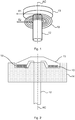
- Fig. 2 schematically shows a cross-section of the coil and armature 13 with rod 12 when placed in a housing 14.
- the housing 14 is provided with a first opening at which the coil 10 is fitted.
- the armature 13 may be placed on top of the coil 10 outside of the housing 14 with the rod 12 stretching through the first opening, through the interior of the housing 14 and out through a second opening at the bottom of the housing 14.
- the housing 14 may be rectangular in shape. However this is not necessary. What is of importance is that a magnetic flux concentrator is provided around the coil 10. This magnetic flux concentrator is furthermore in physical contact with the coil. If the coil is circular, the magnetic flux concentrator may radially surround the coil, i.e. surround the coil in the radial direction.
- the magnetic flux concentrator may be provided at least around the first opening of the housing. It is thus possible that only an annular shaped area of the housing round the first opening is a magnetic flux concentrator. It is also possible that the whole upper surface of the housing perpendicular to the coil axis AC is a magnetic flux concentrator. It is finally possible that the whole housing 14 that encloses the primary coil 10 is a magnetic flux concentrator, which is the case in the embodiment shown in fig. 2 .
- This magnetic flux concentrator may be of soft magnetic material or soft ferromagnetic material and may therefore as an example be of iron, magnetic steel or a material like permadyne.
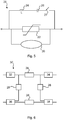
- Fig. 3 schematically shows other elements that may be a part of the actuator in order to actuate the armature.
- a capacitor bank CB comprising a number of series connected capacitors.
- the capacitor bank CB is selectively connectable to the electrical connection terminals T1 and T2 of the first primary coil 10 in order to maneuver the armature 13. For this reason, one end of the series connection is connected to the first connection terminal T1 of the primary coil 10 via an electronic switch SW1, while the other end may be directly connected to the second connection terminal T2 of the primary coil 10.
- An actuator of the type that is based on a Thomson coil may be provided for a mechanical switch. It may thus be provided for breaking or making a galvanic connection between a first and a second electrical conductor.
- Fig. 4 schematically shows one such switch where there is a first and a second conductor 16 and 18 in a vacuum, chamber 17.
- the first conductor 16 is here connected to a first switch terminal T SW1
- the second conductor 18 is connected to a second switch terminal T SW2 in order to connect the switch 20 to other electric devices.
- the second conductor 18 is fixed or stationary, while the first conductor 16 is movable.
- the rod 12 may be attached to the first conductor 16 set to move in synchronism with the armature 13. The direction of movement may also be the same. Thereby the first conductor 16 may physically connect with the second conductor 18 or vice versa.
- the armature 13 may be equipped with means that provides a downward directed force on the rod 12 and thus also forcing the first conductor 16 in galvanic contact with the second conductor 18.
- the capacitor bank CB will be controlled to provide a current pulse to the coil 10, which creates a magnetic flux that is strong enough for overcoming the downward directed force and push the armature 13 upwards and thereby the rod 12 pulls the first conductor 16 away from the second conductor 18, thereby breaking the galvanic contact between the two conductors 16 and 18.
- This type of mechanical switch may for instance be placed in a circuit breaker.
- One circuit breaker 28 that may employ the mechanical switch 20 is schematically shown in fig. 5 .
- a third branch comprising a series connection of an inductance 24, a capacitance 26 and a further switch 27.
- the further switch 27 may be provided as a combination of one or more series connected transistors with antiparallel diodes or as one or more pairs of antiparallel transistors, where the transistors may be insulated gate bipolar transistors (IGBTs).
- IGBTs insulated gate bipolar transistors
- This type of circuit breaker 28 is with advantage used for breaking the current in a power line such as a DC power line in a DC power transmission system.
- the further switch 27 is controlled to pulse the current through the mechanical switch 20 in order to obtain current zero crossings and in relation to one such zero crossing, the first and second conductors are separated from each other through the movement of the armature.
- circuit breaker is merely one type of circuit breaker in which the mechanical switch may be used. There are countless other realizations that may employ the mechanical switch.
- Fig. 6 schematically shows an example of a high voltage system where the circuit breaker 28 may be used.
- the system is here a multi-terminal DC system, such as an HVDC system comprising a number of converters converting between AC and DC.
- Each converter comprises an AC side and a DC side, where the DC side of a first converter 32 is connected to the DC side of a second converter 34 via a first DC line, the DC side of a third converter 36 is connected to the DC side of a fourth converter 38 via a second DC line.
- each circuit breaker 28 has the advantage of being fast through employing a mechanical switch based on a Thomson coil.
- the interconnection may also be considered to form a switch yard in the DC system.
- a mechanical switch being actuated by a Thomson coil based actuator of the type shown in fig. 1 - 4 is thus fast.
- the traditional Thomson coil is inefficient. This may be problematic, at least in high voltage applications.
- the magnetic flux concentrator may be made of a soft magnetic material such as iron or any other ferromagnetic media, such as for instance permadyne, and is used to boost the efficiency of the ultra-fast electromagnetic actuator.
- the housing enclosing the spiral coil that generates the magnetic field is a non-magnetic stainless steel housing that adds mechanical stability.
- a magnetic flux concentrator is used as a housing instead. This will raise the efficiency of the drive considerably. Intuitively, one may often reach the misleading conclusion that since these materials saturate they are unsuitable for use in high magnetic fields.
- the invention is based on the realization that if the actuator is to be used infrequently, which is the case if it used for a circuit breaker, then this saturation is no real problem.
- the Thomson coil has an intermittent operation. Although within such operation, high field levels the concentrator will saturate, it will still be able to help build up the flux rapidly as the concentrator provides a low magnetic reluctance flux path. Therefore, with the same current, a higher field will be generated and thus larger currents will be induced in the armature. This will result in a larger force within the same amount of time thereby significantly increasing performance.
- the magnetic flux concentrator creates a low reluctance path increasing the magnetic field and although the material of the concentrator saturates (points 2 to 3), the field in point 3 is higher than the field in point 1 (which will be the case if a non-magnetic material will be used).
- the mechanical switch is used for disconnecting a power line in the case of a fault, such as in the case of pole to ground fault, a lot of energy can be saved since these capacitors have to be constantly charged to maintain their voltage levels until the next fault appears. Moreover, if the same energizing source is decided to be kept, then the performance of the drive will be radically increased due to the concentrators.
- the concentrator should be placed in a way to close the magnetic path and reduce reluctance.
- a ferromagnetic or a magnetic flux concentrator or perhaps one of permadyne should be used. This shows the potential of using magnetic material such as iron or steel for ultra fast actuators.
- two Thomson coils are used. One may be used for making a galvanic contact and the other for breaking a galvanic contact. In this case there may be a first and a second primary coil, each placed in an opening of a corresponding housing, where one or both may act as magnetic flux concentrator. The primary coils are then facing each other where both may be centered around the same central coil axis. Through these two Thomson coils it is possible that a single armature joined with a rod is set to move between the two coils.
- FIG. 8 shows a view from above of a second type of concentrator together with a coil.
- the concentrator is annular and radially surrounds the coil 10.
- the concentrator may in this case be in the form of an annular disc 44, having a center hole in which the coil is fitted.
- Fig. 9 shows a cross-section through a third type of concentrator and coil.
- the concentrator may in this case be in the form of a solid block 46 having a cavity designed for receiving and holding the coil 10.
- the invention was above described in relation to high voltage operation. It should however be realized that it is not limited to this field.
- the actuator may this for instance be used for low, medium, and high voltage breakers.
- the actuator is actually not limited to be used in circuit breaker, but may for instance be used in a robot as well.
Landscapes
- Physics & Mathematics (AREA)
- Electromagnetism (AREA)
- Electromagnets (AREA)
- Driving Mechanisms And Operating Circuits Of Arc-Extinguishing High-Tension Switches (AREA)
- Breakers (AREA)
Claims (11)
- Aktuator für einen mechanischen Schalter, wobei der Aktuator wenigstens umfasst: einen Anker (13), der mit einem Schaft (12) verbunden ist, eine erste Primärspule (10) mit Wicklungen um eine Spulenmittelachse (AC), die eine Mitte der Spule definiert, und ein erstes Gehäuse (14) zur Aufnahme des Schafts und ausgestattet mit einer ersten Öffnung, wobei der Aktuator auf einer Thomson-Spule basiert, die erste Spule an der ersten Öffnung angebracht ist und der Anker oben auf der Spule so platziert ist, dass er in einer Richtung entlang der Spulenmittelachse von der Spule weg bewegt werden kann, wobei der Schaft dafür vorgesehen ist, sich durch die Mitte der Spule zu bewegen, dadurch gekennzeichnet, dass der Anker außerhalb des Gehäuses angeordnet ist und der Aktuator ferner einen Magnetflusskonzentrator umfasst, der aus wenigstens einem Teil des ersten Gehäuses gebildet ist, wobei der Magnetflusskonzentrator wenigstens rund um die erste Öffnung des Gehäuses und wenigstens rund um die erste Primärspule sowie in physischem Kontakt mit der ersten Primärspule vorgesehen ist.
- Aktuator gemäß Anspruch 1, wobei das gesamte Gehäuse einen Magnetflusskonzentrator bildet.
- Aktuator gemäß einem der vorstehenden Ansprüche, wobei das Material des Magnetflusskonzentrators ein weichmagnetisches Material ist.
- Aktuator gemäß einem der vorstehenden Ansprüche, wobei die erste Primärspule (10) elektrische Verbindungsanschlüsse (T1, T2) aufweist und ferner eine Kondensatorbatterie (Capacitor Bank, CB) umfasst, die selektiv an die elektrischen Verbindungsanschlüsse der ersten Primärspule angeschlossen werden kann, um den Anker (13) zu bewegen.
- Aktuator gemäß Anspruch 4, ferner einen elektrischen Schalter (SW1) umfassend, um selektiv die Kondensatorbatterie (CB) mit den elektrischen Verbindungsanschlüssen (T1, T2) zu verbinden.
- Aktuator gemäß einem der vorstehenden Ansprüche, ferner eine zweite Primärspule mit demselben Aufbau wie die erste Primärspule umfassend, wobei die zweite Primärspule um die Spulenmittelachse zentriert ist, um zu ermöglichen, dass der Anker zwischen der ersten und der zweiten Primärspule hin und her bewegt wird.
- Mechanischer Schalter (20), umfassend einen ersten und einen zweiten Leiter (16, 18) sowie einen Aktuator gemäß einem der vorstehenden Ansprüche, wobei der Aktuator dazu steuerbar ist, einen der Leiter (16) in Bezug auf den anderen (18) zu bewegen, um eine galvanische Verbindung zwischen dem ersten und dem zweiten Leiter herzustellen bzw. zu unterbrechen.
- Schutzschalter (28), der mit einer elektrischen Leitung in Reihe geschaltet ist, um die Leitung zu unterbrechen, wobei der Schutzschalter einen mechanischen Schalter (20) gemäß Anspruch 7 umfasst.
- Hochspannungs-Stromübertragungssystem (30), umfassend wenigstens einen Schutzschalter (28) gemäß Anspruch 8.
- Hochspannungs-Stromübertragungssystem gemäß Anspruch 9, wobei das System ein Hochspannungs-Stromübertragungssystem mit mehreren Anschlüssen ist.
- Hochspannungs-Stromübertragungssystem gemäß Anspruch 9 oder 10, wobei das System ein Gleichstrom (DC)-System ist.
Applications Claiming Priority (1)
| Application Number | Priority Date | Filing Date | Title |
|---|---|---|---|
| PCT/EP2014/059859 WO2015172824A1 (en) | 2014-05-14 | 2014-05-14 | Thomson coil based actuator |
Publications (2)
| Publication Number | Publication Date |
|---|---|
| EP3143631A1 EP3143631A1 (de) | 2017-03-22 |
| EP3143631B1 true EP3143631B1 (de) | 2018-05-09 |
Family
ID=50732170
Family Applications (1)
| Application Number | Title | Priority Date | Filing Date |
|---|---|---|---|
| EP14724427.1A Active EP3143631B1 (de) | 2014-05-14 | 2014-05-14 | Auf thomson-spule basierender aktuator |
Country Status (4)
| Country | Link |
|---|---|
| US (1) | US9911562B2 (de) |
| EP (1) | EP3143631B1 (de) |
| CN (1) | CN106663554B (de) |
| WO (1) | WO2015172824A1 (de) |
Families Citing this family (16)
| Publication number | Priority date | Publication date | Assignee | Title |
|---|---|---|---|---|
| CN106663554B (zh) * | 2014-05-14 | 2018-06-01 | Abb瑞士股份有限公司 | 以汤姆逊线圈为基础的致动器 |
| CA3046146A1 (en) | 2016-12-06 | 2018-06-14 | Hilti Aktiengesellschaft | Electrodynamic drive |
| EP3594972B1 (de) * | 2018-07-13 | 2023-10-04 | ABB Schweiz AG | Antrieb für eine nieder-, mittel- oder hochspannungsschaltanlage und verfahren zu dessen betrieb |
| US10580599B1 (en) | 2018-08-21 | 2020-03-03 | Eaton Intelligent Power Limited | Vacuum circuit interrupter with actuation having active damping |
| SE1851084A1 (en) | 2018-09-14 | 2020-03-15 | Scibreak Ab | Current interrupter with actuator run-time control |
| CN109671595B (zh) * | 2019-01-08 | 2020-01-14 | 程丽娜 | 一种开关 |
| US11069495B2 (en) * | 2019-01-25 | 2021-07-20 | Eaton Intelligent Power Limited | Vacuum switching apparatus and drive mechanism therefor |
| US10796868B2 (en) | 2019-02-11 | 2020-10-06 | Eaton Intelligent Power Limited | Thomson coil integrated moving contact in vacuum interrupter |
| US11152174B2 (en) | 2019-06-19 | 2021-10-19 | Eaton Intelligent Power Limited | Dual thomson coil-actuated, double-bellows vacuum circuit interrupter |
| US11328884B2 (en) | 2019-06-26 | 2022-05-10 | Eaton Intelligent Power Limited | Variable-speed circuit breaker and switching method for same |
| US11107653B2 (en) | 2019-06-26 | 2021-08-31 | Eaton Intelligent Power Limited | Dual-action switching mechanism and pole unit for circuit breaker |
| US11289294B2 (en) | 2019-07-10 | 2022-03-29 | Eaton Intelligent Power Limited | Rotary switch and circuit interrupter including the same |
| EP3913647B1 (de) * | 2020-05-22 | 2023-02-22 | ABB Schweiz AG | Schaltersystem |
| US11183348B1 (en) | 2020-07-21 | 2021-11-23 | Eaton Intelligent Power Limited | Vacuum circuit interrupter with decelerator with integrated latch assembly |
| US11749477B2 (en) | 2021-04-21 | 2023-09-05 | Eaton Intelligent Power Limited | Vacuum circuit interrupter with dual plate actuation |
| CN117859248A (zh) * | 2021-06-11 | 2024-04-09 | 氦核能源有限公司 | 电磁线圈的高速开关设备 |
Family Cites Families (40)
| Publication number | Priority date | Publication date | Assignee | Title |
|---|---|---|---|---|
| GB1229799A (de) * | 1967-11-13 | 1971-04-28 | ||
| US3525963A (en) * | 1968-07-25 | 1970-08-25 | English Electric Co Ltd | Electro-magnetic actuator with armature assembly slidable between two limit positions |
| US4215328A (en) * | 1978-04-17 | 1980-07-29 | Square D Company | Circuit breaker having an electronic fault sensing and trip initiating unit |
| ATE21296T1 (de) * | 1981-12-14 | 1986-08-15 | Sprecher & Schuh Ag | Eisenkernpaar und spulenkoerper fuer wechselstromschuetz. |
| DE3942542A1 (de) * | 1989-12-22 | 1991-06-27 | Lungu Cornelius | Bistabiler magnetantrieb mit permanentmagnetischem hubanker |
| ES2133339T3 (es) * | 1992-03-31 | 1999-09-16 | Ellenberger & Poensgen | Interruptor de proteccion con mando a distancia. |
| US5281936A (en) * | 1992-06-01 | 1994-01-25 | Teledyne Industries, Inc. | Microwave switch |
| US5488340A (en) | 1994-05-20 | 1996-01-30 | Caterpillar Inc. | Hard magnetic valve actuator adapted for a fuel injector |
| US5652558A (en) * | 1996-04-10 | 1997-07-29 | The Narda Microwave Corporation | Double pole double throw RF switch |
| SE9901627D0 (sv) * | 1999-05-03 | 1999-05-03 | Asea Brown Boveri | Elkopplare |
| US6833777B2 (en) * | 2000-04-07 | 2004-12-21 | Siemens Aktiengesellschaft | Switching method for an electromagnetic switching device and an electromagnetic switching device corresponding thereto |
| JP2002124162A (ja) | 2000-10-16 | 2002-04-26 | Mitsubishi Electric Corp | 開閉装置 |
| DE10214992A1 (de) * | 2002-04-05 | 2003-10-16 | Moeller Gmbh | Wechselstrom-Elektromagnet |
| US6657150B1 (en) * | 2002-06-14 | 2003-12-02 | Eaton Corporation | Shorting switch and system to eliminate arcing faults in power distribution equipment |
| CN1253912C (zh) * | 2003-05-29 | 2006-04-26 | 刘平 | 电力开关器 |
| DE102004004708B3 (de) * | 2004-01-30 | 2005-04-21 | Karl Dungs Gmbh & Co. Kg | Magnetventil |
| US7777600B2 (en) | 2004-05-20 | 2010-08-17 | Powerpath Technologies Llc | Eddy current inductive drive electromechanical liner actuator and switching arrangement |
| DE102005013197A1 (de) * | 2005-03-16 | 2006-09-28 | Siemens Ag | Magnetische Betätigungsvorrichtung |
| US20060238285A1 (en) * | 2005-03-30 | 2006-10-26 | Dimig Steven J | Residual magnetic devices and methods |
| US20060226941A1 (en) * | 2005-03-30 | 2006-10-12 | Dimig Steven J | Residual magnetic devices and methods |
| US7401483B2 (en) * | 2005-03-30 | 2008-07-22 | Strattec Security Corporation | Residual magnetic devices and methods for an ignition actuation blockage device |
| US20060226942A1 (en) * | 2005-03-30 | 2006-10-12 | Dimig Steven J | Residual magnetic devices and methods |
| GB0607072D0 (en) | 2006-04-07 | 2006-05-17 | Artemis Intelligent Power Ltd | Electromagnetic actuator |
| EP2149189A2 (de) * | 2007-05-09 | 2010-02-03 | Motor Excellence, LLC | Vorrichtung zur erzeugung elektrischer ausgänge und stromgetriebene elektrische vorrichtung mit rotor- oder statorelementen aus einem bandgewickelten kernlaminat sowie verfahren zu ihrer herstellung und verwendung |
| US8139328B2 (en) * | 2007-05-17 | 2012-03-20 | Levitron Manufacturing Company, Inc. | Fault circuit interrupting device with symmetrical inputs |
| US7830231B2 (en) * | 2008-02-18 | 2010-11-09 | Eaton Corporation | Trip actuator including a thermoplastic bushing, and trip unit and electrical switching apparatus including the same |
| EP2182531B1 (de) | 2008-10-29 | 2014-01-08 | Sauer-Danfoss ApS | Ventilaktuator |
| TWI351325B (en) | 2008-12-09 | 2011-11-01 | Metal Ind Res & Dev Ct | Device for producing patterns and a method thereof |
| DE102009031665B4 (de) | 2009-07-05 | 2016-02-25 | Msm Krystall Gbr (Vertretungsberechtigte Gesellschafter: Dr. Rainer Schneider, 12165 Berlin; Arno Mecklenburg, 10999 Berlin) | Elektrodynamischer Aktor |
| EP2312606B1 (de) * | 2009-10-14 | 2013-02-27 | ABB Technology AG | Bistabiler magnetischer Aktuator für einen Mittelspannungsschutzschalter |
| DE202011050847U1 (de) * | 2010-10-16 | 2011-11-21 | Msm Krystall Gbr (Vertretungsberechtigte Gesellschafter: Dr. Rainer Schneider, 12165 Berlin; Arno Mecklenburg, 10999 Berlin) | Elektromagnetischer Linearaktor |
| US8729416B2 (en) * | 2012-01-23 | 2014-05-20 | Electro-Mechanical Corporation | Circuit breaker remote tripping |
| US20130328650A1 (en) * | 2012-06-06 | 2013-12-12 | Glen A Robertson | Divergent flux path magnetic actuator and devices incorporating the same |
| US9183996B2 (en) * | 2012-06-27 | 2015-11-10 | Abb Technology Ltd | High voltage current interrupter and an actuator system for a high voltage current interrupter |
| US10320276B2 (en) | 2012-10-12 | 2019-06-11 | Rhefor Gbr | Scalable, highly dynamic electromagnetic linear drive with limited travel and low transverse forces |
| US9036320B1 (en) * | 2013-12-02 | 2015-05-19 | Elbex Video Ltd. | Mechanical latching relays and hybrid switches with latching relays for use in electrical automation |
| GB2522696A (en) * | 2014-02-03 | 2015-08-05 | Gen Electric | Improvements in or relating to vacuum switching devices |
| CN106663554B (zh) * | 2014-05-14 | 2018-06-01 | Abb瑞士股份有限公司 | 以汤姆逊线圈为基础的致动器 |
| EP3149757B1 (de) * | 2014-06-02 | 2018-08-08 | ABB Schweiz AG | Hochspannungsdruckgasschalter und leistungsschaltereinheit mit einem derartigen druckgasschalter |
| US9548174B2 (en) * | 2015-04-23 | 2017-01-17 | Tyco Electronics Corporation | Contractor assembly which counteracts electromagnetic repulsion of contacts |
-
2014
- 2014-05-14 CN CN201480078868.1A patent/CN106663554B/zh active Active
- 2014-05-14 WO PCT/EP2014/059859 patent/WO2015172824A1/en active Application Filing
- 2014-05-14 US US15/308,774 patent/US9911562B2/en active Active
- 2014-05-14 EP EP14724427.1A patent/EP3143631B1/de active Active
Non-Patent Citations (1)
| Title |
|---|
| None * |
Also Published As
| Publication number | Publication date |
|---|---|
| US20170154747A1 (en) | 2017-06-01 |
| CN106663554A (zh) | 2017-05-10 |
| CN106663554B (zh) | 2018-06-01 |
| US9911562B2 (en) | 2018-03-06 |
| EP3143631A1 (de) | 2017-03-22 |
| WO2015172824A1 (en) | 2015-11-19 |
Similar Documents
| Publication | Publication Date | Title |
|---|---|---|
| EP3143631B1 (de) | Auf thomson-spule basierender aktuator | |
| EP3043368B1 (de) | Überbrückungsschalter für hochspannungsgleichstromübertragung | |
| Puumala et al. | Electromagnetic design of ultrafast electromechanical switches | |
| CN107946133B (zh) | 一种快速分闸机构及混合式交流断路器 | |
| US10325737B2 (en) | Fast switch device | |
| KR20210118060A (ko) | 다수의 해머 타격식 진공 인터럽터 용접 파괴 | |
| CN110828226A (zh) | 电磁斥力装置及快速开关 | |
| Vilchis-Rodriguez et al. | Finite element analysis and efficiency improvement of the Thomson coil actuator | |
| WO2015062644A1 (en) | Circuit breaker | |
| KR101841859B1 (ko) | 전자기 드라이브를 갖는 회로 차단기 유닛 | |
| WO2014048483A1 (en) | Electrical switch with thomson coil drive | |
| US11621135B2 (en) | Armature for electromagnetic actuator, an electromagnetic actuator, a switch device and a method for manufacturing an armature | |
| WO2012045360A1 (en) | Direct current circuit breaker | |
| CN108573828B (zh) | 用于中压配电装置的开关设备 | |
| CN201741623U (zh) | 户外高压智能型永磁真空开关 | |
| KR20210072104A (ko) | 수동 폐쇄 보조 제어 메커니즘 | |
| EP3531435A1 (de) | Laststufenschalterwechselvorrichtung und laststufenschalterwechselsystem | |
| Yin et al. | A comparison between moving magnet and moving coil actuators for vacuum interrupters | |
| Sonagra et al. | Controlled switching of non-coupled & coupled reactor for re-ignition free de-energization operation | |
| Yin et al. | Novel fast operating moving coil actuator with compensation coil for HVDC circuit breakers | |
| Parekh et al. | Study of an electromagnetic damping actuator | |
| CN112820580A (zh) | 一种背带式横磁场直流电流转移装置及其应用 | |
| CN213124280U (zh) | 一种断路器 | |
| US20230011724A1 (en) | Magnetic latching actuator | |
| CN106206174B (zh) | 平衡力式磁保持接触器 |
Legal Events
| Date | Code | Title | Description |
|---|---|---|---|
| PUAI | Public reference made under article 153(3) epc to a published international application that has entered the european phase |
Free format text: ORIGINAL CODE: 0009012 |
|
| 17P | Request for examination filed |
Effective date: 20161214 |
|
| AK | Designated contracting states |
Kind code of ref document: A1 Designated state(s): AL AT BE BG CH CY CZ DE DK EE ES FI FR GB GR HR HU IE IS IT LI LT LU LV MC MK MT NL NO PL PT RO RS SE SI SK SM TR |
|
| AX | Request for extension of the european patent |
Extension state: BA ME |
|
| DAX | Request for extension of the european patent (deleted) | ||
| GRAP | Despatch of communication of intention to grant a patent |
Free format text: ORIGINAL CODE: EPIDOSNIGR1 |
|
| INTG | Intention to grant announced |
Effective date: 20171212 |
|
| GRAS | Grant fee paid |
Free format text: ORIGINAL CODE: EPIDOSNIGR3 |
|
| GRAA | (expected) grant |
Free format text: ORIGINAL CODE: 0009210 |
|
| AK | Designated contracting states |
Kind code of ref document: B1 Designated state(s): AL AT BE BG CH CY CZ DE DK EE ES FI FR GB GR HR HU IE IS IT LI LT LU LV MC MK MT NL NO PL PT RO RS SE SI SK SM TR |
|
| REG | Reference to a national code |
Ref country code: GB Ref legal event code: FG4D |
|
| REG | Reference to a national code |
Ref country code: CH Ref legal event code: EP Ref country code: AT Ref legal event code: REF Ref document number: 998275 Country of ref document: AT Kind code of ref document: T Effective date: 20180515 |
|
| REG | Reference to a national code |
Ref country code: DE Ref legal event code: R096 Ref document number: 602014025218 Country of ref document: DE Ref country code: IE Ref legal event code: FG4D |
|
| REG | Reference to a national code |
Ref country code: DE Ref legal event code: R084 Ref document number: 602014025218 Country of ref document: DE |
|
| REG | Reference to a national code |
Ref country code: NL Ref legal event code: MP Effective date: 20180509 |
|
| REG | Reference to a national code |
Ref country code: LT Ref legal event code: MG4D |
|
| PG25 | Lapsed in a contracting state [announced via postgrant information from national office to epo] |
Ref country code: ES Free format text: LAPSE BECAUSE OF FAILURE TO SUBMIT A TRANSLATION OF THE DESCRIPTION OR TO PAY THE FEE WITHIN THE PRESCRIBED TIME-LIMIT Effective date: 20180509 Ref country code: LT Free format text: LAPSE BECAUSE OF FAILURE TO SUBMIT A TRANSLATION OF THE DESCRIPTION OR TO PAY THE FEE WITHIN THE PRESCRIBED TIME-LIMIT Effective date: 20180509 Ref country code: FI Free format text: LAPSE BECAUSE OF FAILURE TO SUBMIT A TRANSLATION OF THE DESCRIPTION OR TO PAY THE FEE WITHIN THE PRESCRIBED TIME-LIMIT Effective date: 20180509 Ref country code: NO Free format text: LAPSE BECAUSE OF FAILURE TO SUBMIT A TRANSLATION OF THE DESCRIPTION OR TO PAY THE FEE WITHIN THE PRESCRIBED TIME-LIMIT Effective date: 20180809 Ref country code: BG Free format text: LAPSE BECAUSE OF FAILURE TO SUBMIT A TRANSLATION OF THE DESCRIPTION OR TO PAY THE FEE WITHIN THE PRESCRIBED TIME-LIMIT Effective date: 20180809 Ref country code: SE Free format text: LAPSE BECAUSE OF FAILURE TO SUBMIT A TRANSLATION OF THE DESCRIPTION OR TO PAY THE FEE WITHIN THE PRESCRIBED TIME-LIMIT Effective date: 20180509 |
|
| PG25 | Lapsed in a contracting state [announced via postgrant information from national office to epo] |
Ref country code: RS Free format text: LAPSE BECAUSE OF FAILURE TO SUBMIT A TRANSLATION OF THE DESCRIPTION OR TO PAY THE FEE WITHIN THE PRESCRIBED TIME-LIMIT Effective date: 20180509 Ref country code: LV Free format text: LAPSE BECAUSE OF FAILURE TO SUBMIT A TRANSLATION OF THE DESCRIPTION OR TO PAY THE FEE WITHIN THE PRESCRIBED TIME-LIMIT Effective date: 20180509 Ref country code: HR Free format text: LAPSE BECAUSE OF FAILURE TO SUBMIT A TRANSLATION OF THE DESCRIPTION OR TO PAY THE FEE WITHIN THE PRESCRIBED TIME-LIMIT Effective date: 20180509 Ref country code: GR Free format text: LAPSE BECAUSE OF FAILURE TO SUBMIT A TRANSLATION OF THE DESCRIPTION OR TO PAY THE FEE WITHIN THE PRESCRIBED TIME-LIMIT Effective date: 20180810 Ref country code: NL Free format text: LAPSE BECAUSE OF FAILURE TO SUBMIT A TRANSLATION OF THE DESCRIPTION OR TO PAY THE FEE WITHIN THE PRESCRIBED TIME-LIMIT Effective date: 20180509 |
|
| REG | Reference to a national code |
Ref country code: CH Ref legal event code: PL |
|
| REG | Reference to a national code |
Ref country code: AT Ref legal event code: MK05 Ref document number: 998275 Country of ref document: AT Kind code of ref document: T Effective date: 20180509 |
|
| REG | Reference to a national code |
Ref country code: BE Ref legal event code: MM Effective date: 20180531 |
|
| PG25 | Lapsed in a contracting state [announced via postgrant information from national office to epo] |
Ref country code: RO Free format text: LAPSE BECAUSE OF FAILURE TO SUBMIT A TRANSLATION OF THE DESCRIPTION OR TO PAY THE FEE WITHIN THE PRESCRIBED TIME-LIMIT Effective date: 20180509 Ref country code: CZ Free format text: LAPSE BECAUSE OF FAILURE TO SUBMIT A TRANSLATION OF THE DESCRIPTION OR TO PAY THE FEE WITHIN THE PRESCRIBED TIME-LIMIT Effective date: 20180509 Ref country code: SK Free format text: LAPSE BECAUSE OF FAILURE TO SUBMIT A TRANSLATION OF THE DESCRIPTION OR TO PAY THE FEE WITHIN THE PRESCRIBED TIME-LIMIT Effective date: 20180509 Ref country code: PL Free format text: LAPSE BECAUSE OF FAILURE TO SUBMIT A TRANSLATION OF THE DESCRIPTION OR TO PAY THE FEE WITHIN THE PRESCRIBED TIME-LIMIT Effective date: 20180509 Ref country code: DK Free format text: LAPSE BECAUSE OF FAILURE TO SUBMIT A TRANSLATION OF THE DESCRIPTION OR TO PAY THE FEE WITHIN THE PRESCRIBED TIME-LIMIT Effective date: 20180509 Ref country code: EE Free format text: LAPSE BECAUSE OF FAILURE TO SUBMIT A TRANSLATION OF THE DESCRIPTION OR TO PAY THE FEE WITHIN THE PRESCRIBED TIME-LIMIT Effective date: 20180509 Ref country code: AT Free format text: LAPSE BECAUSE OF FAILURE TO SUBMIT A TRANSLATION OF THE DESCRIPTION OR TO PAY THE FEE WITHIN THE PRESCRIBED TIME-LIMIT Effective date: 20180509 |
|
| REG | Reference to a national code |
Ref country code: DE Ref legal event code: R097 Ref document number: 602014025218 Country of ref document: DE |
|
| REG | Reference to a national code |
Ref country code: IE Ref legal event code: MM4A |
|
| PG25 | Lapsed in a contracting state [announced via postgrant information from national office to epo] |
Ref country code: SM Free format text: LAPSE BECAUSE OF FAILURE TO SUBMIT A TRANSLATION OF THE DESCRIPTION OR TO PAY THE FEE WITHIN THE PRESCRIBED TIME-LIMIT Effective date: 20180509 Ref country code: LI Free format text: LAPSE BECAUSE OF NON-PAYMENT OF DUE FEES Effective date: 20180531 Ref country code: CH Free format text: LAPSE BECAUSE OF NON-PAYMENT OF DUE FEES Effective date: 20180531 Ref country code: IT Free format text: LAPSE BECAUSE OF FAILURE TO SUBMIT A TRANSLATION OF THE DESCRIPTION OR TO PAY THE FEE WITHIN THE PRESCRIBED TIME-LIMIT Effective date: 20180509 |
|
| PLBE | No opposition filed within time limit |
Free format text: ORIGINAL CODE: 0009261 |
|
| STAA | Information on the status of an ep patent application or granted ep patent |
Free format text: STATUS: NO OPPOSITION FILED WITHIN TIME LIMIT |
|
| PG25 | Lapsed in a contracting state [announced via postgrant information from national office to epo] |
Ref country code: MC Free format text: LAPSE BECAUSE OF FAILURE TO SUBMIT A TRANSLATION OF THE DESCRIPTION OR TO PAY THE FEE WITHIN THE PRESCRIBED TIME-LIMIT Effective date: 20180509 Ref country code: LU Free format text: LAPSE BECAUSE OF NON-PAYMENT OF DUE FEES Effective date: 20180514 |
|
| 26N | No opposition filed |
Effective date: 20190212 |
|
| GBPC | Gb: european patent ceased through non-payment of renewal fee |
Effective date: 20180809 |
|
| PG25 | Lapsed in a contracting state [announced via postgrant information from national office to epo] |
Ref country code: FR Free format text: LAPSE BECAUSE OF NON-PAYMENT OF DUE FEES Effective date: 20180709 Ref country code: IE Free format text: LAPSE BECAUSE OF NON-PAYMENT OF DUE FEES Effective date: 20180514 |
|
| PG25 | Lapsed in a contracting state [announced via postgrant information from national office to epo] |
Ref country code: BE Free format text: LAPSE BECAUSE OF NON-PAYMENT OF DUE FEES Effective date: 20180531 Ref country code: SI Free format text: LAPSE BECAUSE OF FAILURE TO SUBMIT A TRANSLATION OF THE DESCRIPTION OR TO PAY THE FEE WITHIN THE PRESCRIBED TIME-LIMIT Effective date: 20180509 |
|
| PG25 | Lapsed in a contracting state [announced via postgrant information from national office to epo] |
Ref country code: GB Free format text: LAPSE BECAUSE OF NON-PAYMENT OF DUE FEES Effective date: 20180809 |
|
| PG25 | Lapsed in a contracting state [announced via postgrant information from national office to epo] |
Ref country code: AL Free format text: LAPSE BECAUSE OF FAILURE TO SUBMIT A TRANSLATION OF THE DESCRIPTION OR TO PAY THE FEE WITHIN THE PRESCRIBED TIME-LIMIT Effective date: 20180509 |
|
| PG25 | Lapsed in a contracting state [announced via postgrant information from national office to epo] |
Ref country code: MT Free format text: LAPSE BECAUSE OF NON-PAYMENT OF DUE FEES Effective date: 20180514 |
|
| PG25 | Lapsed in a contracting state [announced via postgrant information from national office to epo] |
Ref country code: TR Free format text: LAPSE BECAUSE OF FAILURE TO SUBMIT A TRANSLATION OF THE DESCRIPTION OR TO PAY THE FEE WITHIN THE PRESCRIBED TIME-LIMIT Effective date: 20180509 |
|
| PG25 | Lapsed in a contracting state [announced via postgrant information from national office to epo] |
Ref country code: PT Free format text: LAPSE BECAUSE OF FAILURE TO SUBMIT A TRANSLATION OF THE DESCRIPTION OR TO PAY THE FEE WITHIN THE PRESCRIBED TIME-LIMIT Effective date: 20180509 |
|
| PG25 | Lapsed in a contracting state [announced via postgrant information from national office to epo] |
Ref country code: MK Free format text: LAPSE BECAUSE OF NON-PAYMENT OF DUE FEES Effective date: 20180509 Ref country code: HU Free format text: LAPSE BECAUSE OF FAILURE TO SUBMIT A TRANSLATION OF THE DESCRIPTION OR TO PAY THE FEE WITHIN THE PRESCRIBED TIME-LIMIT; INVALID AB INITIO Effective date: 20140514 Ref country code: CY Free format text: LAPSE BECAUSE OF FAILURE TO SUBMIT A TRANSLATION OF THE DESCRIPTION OR TO PAY THE FEE WITHIN THE PRESCRIBED TIME-LIMIT Effective date: 20180509 |
|
| PG25 | Lapsed in a contracting state [announced via postgrant information from national office to epo] |
Ref country code: IS Free format text: LAPSE BECAUSE OF FAILURE TO SUBMIT A TRANSLATION OF THE DESCRIPTION OR TO PAY THE FEE WITHIN THE PRESCRIBED TIME-LIMIT Effective date: 20180909 |
|
| PGFP | Annual fee paid to national office [announced via postgrant information from national office to epo] |
Ref country code: DE Payment date: 20230519 Year of fee payment: 10 |