EP1513749B1 - Transport de pieces en vrac - Google Patents
Transport de pieces en vrac Download PDFInfo
- Publication number
- EP1513749B1 EP1513749B1 EP03724770A EP03724770A EP1513749B1 EP 1513749 B1 EP1513749 B1 EP 1513749B1 EP 03724770 A EP03724770 A EP 03724770A EP 03724770 A EP03724770 A EP 03724770A EP 1513749 B1 EP1513749 B1 EP 1513749B1
- Authority
- EP
- European Patent Office
- Prior art keywords
- bulk material
- oscillating
- oscillating conveyor
- zone
- material items
- Prior art date
- Legal status (The legal status is an assumption and is not a legal conclusion. Google has not performed a legal analysis and makes no representation as to the accuracy of the status listed.)
- Expired - Lifetime
Links
- 239000013590 bulk material Substances 0.000 title claims abstract description 134
- 230000010355 oscillation Effects 0.000 claims abstract description 12
- 230000002441 reversible effect Effects 0.000 claims abstract description 8
- 230000033001 locomotion Effects 0.000 claims description 45
- 238000003860 storage Methods 0.000 claims description 30
- 238000009826 distribution Methods 0.000 claims description 18
- 238000000034 method Methods 0.000 claims description 17
- 238000005452 bending Methods 0.000 claims description 13
- 230000001133 acceleration Effects 0.000 claims description 11
- 230000003313 weakening effect Effects 0.000 claims description 11
- 238000013016 damping Methods 0.000 claims description 9
- 239000004952 Polyamide Substances 0.000 claims description 4
- 238000001514 detection method Methods 0.000 claims description 4
- 239000000463 material Substances 0.000 claims description 4
- 229920002647 polyamide Polymers 0.000 claims description 4
- 239000004745 nonwoven fabric Substances 0.000 claims description 2
- 230000009467 reduction Effects 0.000 claims description 2
- 238000005096 rolling process Methods 0.000 claims description 2
- 239000002759 woven fabric Substances 0.000 claims description 2
- 238000011065 in-situ storage Methods 0.000 claims 1
- 230000008569 process Effects 0.000 description 7
- 230000005284 excitation Effects 0.000 description 6
- 230000003534 oscillatory effect Effects 0.000 description 4
- 230000007704 transition Effects 0.000 description 4
- 230000015572 biosynthetic process Effects 0.000 description 3
- 230000008859 change Effects 0.000 description 3
- 230000001419 dependent effect Effects 0.000 description 3
- 239000010410 layer Substances 0.000 description 3
- 239000012528 membrane Substances 0.000 description 3
- 230000002829 reductive effect Effects 0.000 description 3
- 229910000639 Spring steel Inorganic materials 0.000 description 2
- 230000005540 biological transmission Effects 0.000 description 2
- 238000004140 cleaning Methods 0.000 description 2
- 230000008030 elimination Effects 0.000 description 2
- 238000003379 elimination reaction Methods 0.000 description 2
- 230000002349 favourable effect Effects 0.000 description 2
- 238000004519 manufacturing process Methods 0.000 description 2
- 230000036961 partial effect Effects 0.000 description 2
- 238000000926 separation method Methods 0.000 description 2
- 230000035939 shock Effects 0.000 description 2
- 238000005299 abrasion Methods 0.000 description 1
- 230000009471 action Effects 0.000 description 1
- XAGFODPZIPBFFR-UHFFFAOYSA-N aluminium Chemical compound [Al] XAGFODPZIPBFFR-UHFFFAOYSA-N 0.000 description 1
- 229910052782 aluminium Inorganic materials 0.000 description 1
- 238000012512 characterization method Methods 0.000 description 1
- 238000006243 chemical reaction Methods 0.000 description 1
- 239000011248 coating agent Substances 0.000 description 1
- 238000000576 coating method Methods 0.000 description 1
- 239000004020 conductor Substances 0.000 description 1
- 238000010276 construction Methods 0.000 description 1
- 230000002950 deficient Effects 0.000 description 1
- 238000010586 diagram Methods 0.000 description 1
- 238000006073 displacement reaction Methods 0.000 description 1
- 230000000694 effects Effects 0.000 description 1
- 239000013013 elastic material Substances 0.000 description 1
- 230000005764 inhibitory process Effects 0.000 description 1
- 239000002245 particle Substances 0.000 description 1
- 230000000737 periodic effect Effects 0.000 description 1
- 230000008092 positive effect Effects 0.000 description 1
- 238000010926 purge Methods 0.000 description 1
- 230000003134 recirculating effect Effects 0.000 description 1
- 230000006798 recombination Effects 0.000 description 1
- 238000005215 recombination Methods 0.000 description 1
- 230000008521 reorganization Effects 0.000 description 1
- 239000012858 resilient material Substances 0.000 description 1
- 230000000284 resting effect Effects 0.000 description 1
- 230000033764 rhythmic process Effects 0.000 description 1
- 239000002356 single layer Substances 0.000 description 1
- 230000003068 static effect Effects 0.000 description 1
- 238000002604 ultrasonography Methods 0.000 description 1
Images


Classifications
-
- B—PERFORMING OPERATIONS; TRANSPORTING
- B65—CONVEYING; PACKING; STORING; HANDLING THIN OR FILAMENTARY MATERIAL
- B65G—TRANSPORT OR STORAGE DEVICES, e.g. CONVEYORS FOR LOADING OR TIPPING, SHOP CONVEYOR SYSTEMS OR PNEUMATIC TUBE CONVEYORS
- B65G47/00—Article or material-handling devices associated with conveyors; Methods employing such devices
- B65G47/02—Devices for feeding articles or materials to conveyors
- B65G47/04—Devices for feeding articles or materials to conveyors for feeding articles
- B65G47/12—Devices for feeding articles or materials to conveyors for feeding articles from disorderly-arranged article piles or from loose assemblages of articles
- B65G47/14—Devices for feeding articles or materials to conveyors for feeding articles from disorderly-arranged article piles or from loose assemblages of articles arranging or orientating the articles by mechanical or pneumatic means during feeding
- B65G47/1492—Devices for feeding articles or materials to conveyors for feeding articles from disorderly-arranged article piles or from loose assemblages of articles arranging or orientating the articles by mechanical or pneumatic means during feeding the articles being fed from a feeding conveyor
-
- B—PERFORMING OPERATIONS; TRANSPORTING
- B65—CONVEYING; PACKING; STORING; HANDLING THIN OR FILAMENTARY MATERIAL
- B65G—TRANSPORT OR STORAGE DEVICES, e.g. CONVEYORS FOR LOADING OR TIPPING, SHOP CONVEYOR SYSTEMS OR PNEUMATIC TUBE CONVEYORS
- B65G27/00—Jigging conveyors
- B65G27/10—Applications of devices for generating or transmitting jigging movements
- B65G27/32—Applications of devices for generating or transmitting jigging movements with means for controlling direction, frequency or amplitude of vibration or shaking movement
-
- B—PERFORMING OPERATIONS; TRANSPORTING
- B65—CONVEYING; PACKING; STORING; HANDLING THIN OR FILAMENTARY MATERIAL
- B65G—TRANSPORT OR STORAGE DEVICES, e.g. CONVEYORS FOR LOADING OR TIPPING, SHOP CONVEYOR SYSTEMS OR PNEUMATIC TUBE CONVEYORS
- B65G43/00—Control devices, e.g. for safety, warning or fault-correcting
- B65G43/08—Control devices operated by article or material being fed, conveyed or discharged
Definitions
- the invention relates to a device, a method for feeding bulk material from a multiply stacked mass in a memory into a stochastically reorientable, individually distributed and entwined position within reach of a robot, wherein the device comprises a substantially horizontally arranged vibrating conveyor surface with means for advancing or retraction of the bulk material parts in the x- or in the x- and y- direction of the spatial coordinates, means for exciting an at least partial vibration of the vibratory conveyor surface in the z direction of the spatial coordinates, a vision system with a camera or a sensor for individually detecting the number, position and Alignment of the separated bulk material parts, and a processor for processing the sensor signals and for generating control commands to actuators includes.
- baffles must be specifically optimized for each type of bulk material.
- the flexibility of the spiral conveyor is in The past 10 to 15 years have been further improved by the use of active baffles (sensor / actuator) and interchangeable baffles / positioning stations, but can not yet meet today's demands of the industry for flexible, self-destructive feeders that can be programmed for different bulk material parts.
- a known device 10 for flexible feeding of bulk material parts 12 these are partially processed in a memory 14.
- the bulk material parts 12 leave the storage 14 on a conveying surface 16 and travel in the direction of a robot 18 with a pivoting arm 20, which carries a stimulus on a height adjustable shaft 22 fixed to this shaft 22 rotatable gripping tool 24 for bulk material 12.
- a camera 26 determines the exact position of the bulk material parts 12 in the desired preferred position in a selection zone 28 represented by dotted lines.
- a robot controller 30 calculates the coordinates based on transmitted data and controls the actuators of the robot 18 accordingly, this takes the bulk material parts 12, which are arranged in the mentioned desired preferred position, in seconds.
- the removed bulk material parts 12 are placed on a conveyor belt 34 and fed to the further processing, which is indicated by an arrow 32.
- the bulk material parts 12 not gripped by the robot 18 are recycled in the storage 14 and, with further bulk goods 12 stored in the storage, again in a stochastic arrangement via the conveying surface 16 into the selection zone 28 led.
- a 5687831 a device for feeding bulk material parts is described, which comprises a substantially horizontal conveying surface.
- the bulk material parts are transported to a selection zone, where the conveniently arranged and aligned bulk material parts are located by means of a video camera, grabbed by a robot and transferred to a mounting system.
- the non-removed bulk material parts are returned by means of a recirculation system for a new passage to the beginning of the conveying surface.
- the position and orientation of the bulk material parts is changed so that they are aligned as cheaply as possible during the next pass and may possibly be selected and removed in the selection zone.
- the device according to the US, A 5687831 can probably edit a wide variance of bulk material forms, but it is constructively relatively expensive and requires a considerable volume of construction for the arrangement of the conveying surface, the selection zone and the recirculation system.
- a flexible membrane for transporting flexible bulk material parts is arranged, on which a selection zone is defined. In this area, the location of the bulk material parts is analyzed by a machine vision system.
- the sensor signals are converted in a processor into control commands which selectively trigger the transmission of a pulse to specific locations of the flexible membrane, thereby changing the position of at least some bulk material in the selection zone and bringing it into a desired positive orientation.
- a feed device for bulk material parts to a robot according to WO, A1 00/69240 comprises a selection zone accessible to the robot of a device for stochastically changing the position and / or the orientation and a device with a part circulation element for recirculating the non-grabbed bulk material parts.
- the device for stochastic changing the position and / or the orientation of the bulk material parts is a simultaneously formed as a selection zone Studttelde. In a first relative position of Rezirkulationselement and Hinttelde this can be charged with bulk material parts of the recirculation element. In a second relative position, the bulk material falling off the vibratory platform can be caught by the recirculation element.
- a first step the vibrating platform is loaded with bulk material parts from the Generalerezirkulationselement.
- a second step bulk material particles falling from the vibrating platform are collected by the recirculation element.
- the position and / or orientation of the bulk material on the vibrating platform is stochastically changed.
- the position and orientation of the bulk material parts is detected and the data transmitted to the robot, which takes in a fifth step bulk material parts in a favorable position and orientation and transported away.
- the number of bulk material remaining on the vibrating platform is determined and, depending on the result, returned to the first or third step.
- the inventor has set himself the task to provide a device and a method of the type mentioned, which further improve the feeding of bulk material parts from a memory to a robot and simplify.
- an integrally formed vibrating conveyor surface is supported by a vibrating conveyor arm, which vibratory conveyor surface is horizontally displaceable with first or first and second means in the x or in the x and y directions and from a storage zone extends over a distribution zone to the front end of a selection zone for the bulk material parts and freely projecting together with the Schwingbibarm, the memory, distribution and selection zone have a border with play to vibratory feeder conveyor surface, and third means for generating the oscillatory motion in the z direction are connected to the vibrating conveyor.
- Special and further embodiments of the inventive device are the subject of dependent claims.
- the vibrating conveyor arm is substantially board-shaped and generally elongated, consists of a sufficiently mechanically strong, elastic material, can oscillate freely in the area of the distribution and selection zone within the border and so raise the bulk material parts for a Reorient réelle.
- the feed and a possible retraction of the bulk material parts takes place in that the one-piece vibratory conveying surface supported by the vibrating conveyor arm extends linearly in the x direction of the free end of the selection zone or first and second means in the x direction of the front end of the selection zone and in y Direction is perpendicular to it. In both cases, a targeted conveying direction is possible by appropriate means of the first or first and second means.
- the vibrating conveyor is usually permanently mounted in the area of the storage zone, but can be slidably mounted in smaller systems thanks to the smaller mass of the vibrating conveyor in x- or x- and y-direction and be firmly connected to the vibrating conveyor.
- a vibratory conveying arm which can be moved in the x or x and y directions could lead to inadmissible oscillations of the machine table due to the larger mass.
- a predetermined bending area is preferably formed in the vibratory conveying arm, which is achieved, for example, by at least a transverse weakening groove and / or bore takes place.
- a weakening groove is expediently arranged at the bottom, two weakening grooves can be arranged below one another or above one another, the latter only if the vibratory conveying surface resting on the vibrating conveyor arm is sufficiently loadable in the region of the groove. More than two grooves are arranged analogously. Likewise, two or more holes may be arranged adjacent to or above each other, also in combination with grooves. The geometric cross-sectional shape of grooves and bores is not essential.
- the vibrating conveyor arm may be formed to form a weakening line in two parts, wherein the two parts are connected to at least one spring, preferably one or more leaf springs, for example made of spring steel.
- the formation of a weakening line causes the vibrating conveyor arm acts practically like a hinge and has a much lower spring action.
- the spring constant of the Schwingschiarms with respect to this "rotation axis" is practically determined by the spring of a lifting cylinder for the vibration excitation in the z direction.
- the first and second means which act on the oscillating conveyor surface or on the oscillating conveyor arm in the x direction and optionally also in the y direction, as well as the third means, which are preferably cushioned on the third means acting on the oscillating conveyor arm in the z direction, are in practice, for example, per se known pneumatic or hydraulic lifting cylinder with piston and piston rod, but it can also be used electric linear or stepper motors. For example, because of the fast stroke in fractions of a second, spindles with a runner would be more problematic.
- the vibrating conveyor surface In the period between the detection of the position and orientation of the bulk material parts in a favorable position and the gripping by the robot, the vibrating conveyor surface must not move in the x- or y-direction, because otherwise the calculated based on the sensor signals from the processor coordinates for seizure from cheap arranged bulk material parts would not vote anymore. Likewise, during this time period, the oscillatory movement in the z direction must be stopped. This is usually done with a vibratory motion in the z direction damping means on the vibrating conveyor, expediently with a known damping cylinder, a rubber ball or a rubber bellows.
- a sensor for measuring the deflection and frequency is expediently arranged under the vibrating conveyor. From the transmitted measured values, the processor can calculate the natural frequency of the vibrating conveyor arm with the components attached to it and for each location on the vibrating conveyor surface the amplitude and evaluate it for industrial processes.
- the natural frequency of the oscillation in the z-direction is also influenced by the formation of weakening grooves and / or holes in the predetermined bending region. In this way, the energy required for the generation of a swinging motion can be reduced and the process can be made more efficient than at a frequency that is fundamentally also possible other than the natural frequency.
- the frontal border of the selection zone which ends the advancing movement of the bulk material, is preferably designed to be removable automatically, in particular as a slide, door or flap.
- the vibrating conveyor can be emptied quickly and easily in all zones, including the storage tank, also automatically.
- the removable part of the border is expediently designed as a slide, door or flap.
- the vibrating conveyor can be replaced, it consists for example of a polyamide.
- the vibrating conveyor surface for changing the Stored friction or roughened be formed or have a coating, in particular of a woven or nonwoven fabric.
- the vibratory conveying surface must not only have optimal static friction but also low abrasion, ie be mechanically as resistant to wear as possible.
- the vibrating conveyor arm with the vibratory conveying surface is designed to be transparent, at least in the region of the selection zone, and a backlight is arranged below this zone.
- the object is achieved according to the invention in that a swinging motion in the z direction is produced with a programmable amplitude which increases continuously in the x direction, thereby correspondingly increased speed and acceleration of the bulk material parts. which takes place alternately or at least partially simultaneously and in coordination with a feed or retraction conveyance of the bulk material in the x- or in the x- and y- direction, wherein during the time period of a snapshot through the vision system to the removal of bulk material by the robot all movements of the vibrating conveyor stopped in x- or in the x- and y- direction and dampened or stopped the oscillatory movements in the z direction.
- Special and further process variants are the subject of dependent claims.
- the degree of reorganization and the individualization in the direction of the frontal end of the selection zone likewise increase continuously, which has a positive effect on the practical course of the process.
- the oscillation amplitude which increases in the x direction, is preferably produced by transmitting a programmable oscillating movement, in particular a frequency of 5 to 30 Hz, on a the vibratory conveying surface over the entire surface supporting, aussefialb a storage zone cantilevered vibratory conveying arm generated.
- a programmable oscillating movement in particular a frequency of 5 to 30 Hz
- the inventively integrally formed vibratory conveyor also allows the feeding of small and flat bulk material parts, which would sometimes jam or even disappear during the transition from one vibrating conveyor to the other.
- the feed movement of the vibratory conveying arm over the entire surface supported or connected thereto vibrating conveyor surface in the x- or in the x- and y- direction and the corresponding retraction movement with different acceleration When conveying in the direction of the end face of the selection zone, the acceleration for forward movement takes place so slowly that the bulk material parts do not slide or slip only slightly. The acceleration to the retracting movement, however, takes place so fast in this conveying direction that the bulk material parts stay in place because of their inertia or move only slightly. Both movements occur within fractions of a second.
- the bulk material on the vibrating conveyor surface is separated and stochastically distributed in a random position. In this way, a feed of several centimeters per second can be achieved in the area of the selection zone, the bulk material parts are present in sufficient numbers and sufficiently distributed for the gripper of the robot.
- a backward movement can be achieved instead of a feed motion, in that the slower movement in the x- or x- and y-direction takes place against the storage zone, the faster against the selection zone.
- An advancing movement of the bulk material parts can also be achieved by abruptly breaking off a forward movement and, due to the kinetic energy of the bulk material parts, causing their slipping, for example by a hard stop, but the backward movement is broken off more slowly becomes.
- combinations of the two feed or retraction variants are possible.
- All movements of the vibrating conveyor surface in the x-, y- and / or z-direction are preferably controlled and coordinated by the processor according to signals from the camera or another sensor on the number, position and / or orientation of bulk material in the selection zone.
- movements of the vibrating conveyor surface in the x- or x- and y- direction of the advance or retraction of the bulk material parts can be determined by the amplitude and frequency of the oscillatory motion in the z direction, the stochastic change in the orientation of these bulk material parts.
- Faulty bulk material parts are usually not aligned after numerous working cycles so that they are recognized by the vision system and grabbed by the robot with the same probability as the others, resulting in the selection zone to an enrichment of "bad" bulk material parts.
- the processor When exceeding a determined on the basis of signals from the camera or other sensor portion of "bad" bulk material in the selection zone, the processor preferably controls an actuator for the automatic opening of the frontal border, whereby all located in the selection zone bulk material parts are removed, "good” and "bad". Expediently, the opening of the front-side border takes place only after a reduction or inhibition of the supply of bulk material from the storage zone, so that the proportion of excreted "good” bulk material parts can be reduced.
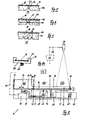
- Fig. 2 shows in plan view a conveying surface 16 with a border 38.
- the one-piece conveying surface 16 is functionally divided into a storage zone 40, a distribution zone 42 and a selection zone 28, wherein the transition from zone to zone not sharp as shown with lines, but within an area is flowing and without interruption on the surface, in particular between the distribution 42 and selection zone 28.
- the conveying direction of the bulk material parts 12 is designated by the spatial coordinate x.
- the feed of the bulk material parts 12 can take place not only in the x, but also in the x and y directions.
- Fig. 3 shows the arrangement of a cantilevered Schwingmotherarms 44 in the rest position, which is a vibratory conveying surface 16 forming, relative to the swing arm 44 at least in the x-direction displaceable and easily replaceable Layer 46 carries, in the present case of a polyamide plate.
- the vibrating conveyor arm 44 is board-shaped and consists of elastically resilient material of high mechanical strength, for example, an aluminum plate of 100 x 30 x 1 cm. In the transition area from the storage to the distribution zone, a semicylindrical quemut is cut out on the underside, leaving a material thickness of 0.3 cm at the weakest point.
- the fixedly mounted Schwingmotherarm 44 is arranged with play between a stationary border 38 which protrudes below and above and thus protects the disposed on the vibrating conveyor 16 bulk material parts 12 against dropping when the board-shaped Schwingmotherarm 44 in the manner of a springboard in the z direction swings.
- the vibrating conveyor arm 44 projecting far as shown in FIG. 4, with the oscillating conveyor surface 16 displaceably mounted on it can oscillate freely at one end, as represented by the double arrow z, wherein the oscillating conveyor surface resonates.
- the vibrating conveyor arm In the region of the memory 14 or the storage zone 40 (FIG. 2), the vibrating conveyor arm is firmly anchored, but according to a variant, it can also be displaceable in the x or x and z directions.
- a bending zone 48 is formed which narrows by suitable weakening measures in the form of grooves and / or bores and leaf springs connecting two parts (FIGS. 5 to 7) can be located.
- FIG. 4 shows a level line 50 of the bulk material parts 12 (FIGS. 2, 3). This line shows the boundary of the superposed bulk material parts 12 in the memory 14, it is lower against the memory output, in the distribution zone 42, the bulk material parts 12 by the increasing in the x direction oscillation amplitude and speed more and more isolated and are finally in the selection zone 28th individually before.
- FIGS. 5 to 7 show the vibratory conveying arm 44 with the vibrating conveyor surface 16 displaceable thereon in the region of a bending zone 48.
- This bending zone 48 is better localized as shown in FIG. 5 by a cross-sectionally circular shape 52 on the underside of the vibrating conveyor arm 44 and a bore 53.
- the vibrating conveyor arm 44 is formed in two pieces and connected in the bending zone 48 with a leaf spring 51 made of spring steel, which leads to a weakening with a hinge effect.
- the location of the bending zone 48 is effected by three triangular transverse grooves 52 lying at the bottom, which may be identical or different with respect to the cross-sectional area.
- the vibrating conveyor surface 16 according to FIG. 5 is formed by a fleece arranged on a plate 46 which can be displaced in the x-direction, as shown in FIG. 6 by a displaceable plate 46 with transverse and / or diagonal cut-outs 55, which can also run in a corrugated manner.
- the vibrating conveyor surface 16 is formed roughened.
- the plate-shaped layers 46 can be lifted and replaced as needed by the vibrating conveyor 44.
- the vibrating conveyor arm 44 and the layer 46 may be formed integrally for the vibrating conveyor surface 16 and made of the same material, for example of a polyamide.
- An apparatus shown in FIG. 8 for feeding bulk material parts 12 has in a housing 11 a vibrating conveyor surface 16 which is supported over its entire area by a vibrating conveyor arm 44 and which in turn comprises a storage, distribution and selection zone 28.
- a CCD camera 26 or other sensor, eg. B. radar or ultrasound monitors the selection zone 28 and is connected via an only partially indicated electrical conductor 54 with a processor 56 which processes the received signals and selectively controls the various actuators. Collisions of the robot gripper with bulk material parts 12 are also detected and reported, and the processor 56 initiates suitable measures.
- the vibrating conveyor arm 44 with the vibrating conveyor surface 16 is fixedly mounted in the storage zone 40 in a manner known per se and protrudes freely via the distribution 42 and selection zone 28.
- a rectangular cross-section 52 is recessed in the oscillating conveyor arm 44.
- the first means 58 for displacement of the vibrating conveyor arm 44 in the x direction are designed as a pneumatically or hydraulically actuated lifting cylinder 58, wherein the piston rod exerts a shock or tensile force.
- Optional second means 60 are designed analogously, they push or pull the vibrating conveyor surface 16 in the y direction. The two movements are coordinated at the same time or one after the other.
- Third means 62 also designed as a pneumatic or hydraulic cylinder, put the free part of the vibrating conveyor arm 44 in a swinging motion, preferably with the natural frequency of the relevant machine configuration.
- the transmission of the shock pulse of the piston rod is elastic via a spring 64, the lifting movement is thereby coupled less hard.
- this spring 64 With a weakening of the bending zone 48, this spring 64 largely determines the spring constant of the vibrating conveyor arm 44 with the vibrating conveyor surface 16, in particular in the case of strong weakening.
- One of the selection zone 28 fitting end-face part 66 (reject gate) of the border 38 can be actuated with a vertically acting pneumatic or hydraulic cylinder 68, in the present case by lifting.
- the selection zone can be cleaned in a simple manner, the removed bulk material parts 12 fall into a cleaning container 70.
- the border 38 is completely or practically completely severed in the region of the bending zone 48 by a cut 49. As a result, the border 38 be bent or angled with the vibrating conveyor arm 44 and the vibrating conveyor surface 16. According to a variant, the border 38 consists of flexible material.
- the selection zone 28 of vibrating conveyor surface 16 and oscillating conveyor arm 44 is designed to be transparent.
- a backlight 72 (backlight) is arranged, which in particular facilitates the recognition of the orientation of the bulk material parts 12.
- a sensor 74 is arranged below the vibrating conveyor arm 44, which monitors the effective deflection of the vibrating conveyor arm 44 and thus the vibrating conveyor surface 16. If the setpoint for the amplitude of the oscillating movement in the z-direction is exceeded, the third cylinder 62 returns to the home position and a damping means 76 (FIG. 10) in the form of a damping cylinder, moves upwards and stops or brings the vibrating conveyor arm 44 very quickly in a defined horizontal position.
- This sensor 74 is also used to automatically determine the natural frequency for a given machine configuration. When switched on, the vibrating conveyor arm 44 is briefly excited, the processor 56 analyzes the sensor signal and determines the specific natural frequency.
- the raised edge 38 in the frontal region of the storage zone 40 is also formed as a liftable part 78 (purge gate), which is actuated by means not shown. After lifting this part 78 of the memory 14, a product change with other bulk material parts 12 can also be made automatically.
- the robot 18 with swivel arm and gripping tool is merely indicated, it is formed according to FIG. 1.
- a variant of a vibrating conveyor arm 44 is shown with side guides 38, in section at the height of the spring 64.
- the vibrating conveyor surface 16 is guided laterally with clearance in corresponding recesses 39.
- FIGS. 9 and 10 show FIGS. 2 and 4 in greater detail and in FIG. 9 with bulk material parts 12.
- the bulk material parts 12 are multi-layered one above the other so that as many bulk material parts 12 as possible can be stored. Depending on their shape, the bulk material parts 12 are not, but also more or less interlocked.
- the previous or new bulk material parts 12 are filled from an external container 80, which is shown by an arrow 82.
- the emptying after lifting the part 78 of the border 38 is characterized by arrow 88, the bulk material parts 12 fall into the container 80th
- the distribution zone 42 begins, which ends at the detection area of the camera 26 (FIG. 8) or at the selection zone 28 shown in dashed lines.
- the bulk material parts 12 are prepared for entry into the selection zone 28, go through the fast forward and backward movements of the vibrating conveyor surface 16 in the x-direction and increasing in the direction of the selection zone 28 amplitude and speed of oscillation in the z-direction Bulk material parts 12 in a single layer over and singulate.
- the selection zone 28 begins, where the bulk material parts 12 are separated by a distance.
- Bulk material parts 12 'with a "good” position and orientation suitable for gripping by the robot 18 ( Figures 1, 8) are drawn in black, not graspable, "bad” bulk material parts 12 "in an improper orientation black Bulk material parts 12 ', the remaining “bad” bulk material parts 12 “reoriented by vibrations in the z direction, before and / or at the same time new bulk material 12 are pushed by the conveyor system.
- the vision system signals to the feeder when the bulk goods should be reoriented by vertical vibrations. This process is characterized by the two arrows 86.
- a damping element 76 in the present case designed as a damping cylinder, is arranged.
- a bulk material part 12 lies with a weight F 9 on the vibrating conveyor surface 16 of a vibrating conveyor arm 44.
- the coefficient of friction of the bulk material part 12 with respect to the vibrating conveyor surface 16 is ⁇ 0 .
- a frictional force F R must be overcome.
- a cylinder, two abutment surfaces 94, 96 limit the stroke of the piston, which is transmitted via a piston rod 98 to the vibrating conveyor arm 44.
- the initial position of the piston of the cylinder 58 is located on the stop surface 94th
- the piston moves at full speed on the impact surface 96.
- the bulk material 12 slips on the conveying surface by x w , whereby the kinetic energy is destroyed.
- the delay in the impact is much greater than g * ⁇ 0 (FIG. 12).
- the cylinder accelerates with a much greater acceleration than g * ⁇ 0 in the reverse direction and returns to the stop 94. Because of the high retraction acceleration, the bulk material part 12 is retracted only minimally, because of the inertia it slips on the vibrating conveyor surface 12 (FIG. 13). Per stroke results in an advance of Ax.
- the bulk material part 12 can of course also be moved in the reverse direction.
- the amplitude A of the vibrating conveyor arm 44 in the z direction in the region of the sensor 74 is plotted in meters (m) against the time t in milliseconds (msec).
- the excitation by the third means 62 takes place at regular time intervals with a rectangular signal R.
- the deflection takes place in the rhythm ⁇ t of the previously determined natural frequency.
- the amplitude A of the oscillation S increases after each excitation. After reaching the setpoint, the excitation is reduced or at least temporarily omitted. An overshoot of the desired value can be corrected with the damping element 76 (FIG. 10).
- the increase in the vibration amplitude A shown in FIG. 14 occurs at the same location. These vibration amplitudes A change when measured with respect to the x-direction inside or outside this location. A similar increase in the vibration amplitudes A is detected when measured with or without the same excitation at different locations farther from the storage zone 50 with respect to the x-direction.
- FIG. 15 in contrast to FIG. 8, a small device 10 for feeding bulk material parts 12 is shown.
- the vibrating conveyor arm 44 and the vibrating conveyor surface 16 are fixedly connected to each other.
- a linear guide 102 on the base plate 100 guides a carriage 104, which is displaced in the x direction by the horizontal lifting cylinder 58, the first means, and which has an axis of rotation 106 for the oscillating conveyor arm 44.
- the lifting cylinder 62, the third means in the z-direction engages in the region of the storage zone 20 unsprung by a bolt on the vibrating conveyor 44 and stimulates with about 1 mm stroke the vibration with in the direction of the free end increasing amplitude.
- the spring constant is determined by the design of the bending zone 48 with the transverse groove 52. With known structural measures, the vibrating conveyor can also be moved in the x direction.
Claims (16)
- Dispositif destiné à amener des pièces en vrac (12), provenant d'une masse de pièces empilées en couches multiples les unes sur les autres dans un stockage (14), jusqu'à une position où elles sont séparées, réparties individuellement, et réorientables stochastiquement, à portée de saisie d'un robot (18), le dispositif comprenant une surface oscillante (16) de convoyeur disposée essentiellement à l'horizontale et équipée de moyens (58, 60) d'avance ou de recul des pièces en vrac (12) dans la direction x ou les directions x et y des coordonnées spatiales, des moyens (62) communiquant une oscillation à la surface oscillante (16) de convoyeur dans la direction z des coordonnés spatiales, un système de visualisation incluant une caméra (26) ou un capteur pour détecter individuellement le nombre, la position et l'orientation des pièces en vrac isolées (12), et un processeur (56) de traitement des signaux de capteur et de génération d'ordres de commande à des actionneurs,
caractérisé en ce que
la surface oscillante (16) de convoyeur à structure d'un seul tenant est soutenue sur toute sa surface par un bras oscillant (44) de convoyeur, en ce que cette surface oscillante de convoyeur peut coulisser horizontalement sous l'effet de premiers ou de premiers et deuxièmes moyens (58, 60) dans la direction x ou les directions x et y et s'étend depuis une zone de stockage (40) suivie par une zone de répartition (42) jusqu'à l'extrémité frontale d'une zone de sélection (28) pour les pièces en vrac (12), et fait saillie librement avec le bras oscillant (44) de convoyeur, en ce que les zones de stockage (40), de répartition (42) et de sélection (28) comportent une bordure (38) qui ménage un jeu par rapport au bras oscillant (44) de convoyeur et/ou à la surface oscillante (16) de convoyeur, et en ce que les troisièmes moyens (62) de génération d'un mouvement oscillant (S) dans la direction z sont connectés au bras oscillant (44) de convoyeur. - Dispositif selon la revendication 1, caractérisé en ce que le bras oscillant (44) de convoyeur, monté de préférence de façon fixe dans la région de la zone de stockage (40), comporte au moins une rainure (52) et/ou un alésage (53) d'affaiblissement disposé transversalement entre la zone de stockage (40) et la zone de répartition (42), ou consiste en deux éléments connectés par un ressort à lame, pour former une région de flexion programmée.
- Dispositif selon la revendication 1 ou 2, caractérisé en ce que les premiers, deuxièmes et troisièmes moyens (58, 60, 62) consistent en vérins pneumatiques ou hydrauliques, ou en moteurs électriques linéaires ou pas à pas.
- Dispositif selon l'une quelconque des revendications précédentes, caractérisé en ce qu'un élément amortisseur (76), de préférence un vérin amortisseur, est agencé sur le bras oscillant (44) de convoyeur pour réduire ou arrêter temporairement le mouvement oscillant (S) dans la direction z.
- Dispositif selon l'une quelconque des revendications précédentes, caractérisé en ce qu'il comprend un capteur (74) de mesure de l'amplitude (A) et de la fréquence d'oscillation du bras oscillant (44) de convoyeur.
- Dispositif selon l'une quelconque des revendications précédentes, caractérisé en ce que la partie frontale (66) de la bordure (38) de la zone de sélection (28) est amovible, et consiste de préférence en un tiroir, des portes ou un volet.
- Dispositif selon l'une quelconque des revendications précédentes, caractérisé en ce que la bordure frontale (78) de la zone de stockage (40) est amovible, et consiste de préférence en un tiroir, des portes ou un volet.
- Dispositif selon l'une quelconque des revendications précédentes, caractérisé en ce que la surface oscillante (16) de convoyeur, de préférence remplaçable, consiste en une matière résistante à l'usure, dont le coefficient de friction ou la résistance à l'usure est réglable pour les pièces en vrac (12), en particulier en un polyamide, et/ou dont la surface est rendue rugueuse ou structurée, et/ou dont la surface est revêtue, en particulier d'un tissu ou d'un non-tissé.
- Dispositif selon l'une quelconque des revendications précédentes, caractérisé en ce que le bras oscillant (44) de convoyeur et la surface oscillante (16) de convoyeur sont transparents au moins dans la région de la zone de sélection (28), et qu'un éclairage (72) par transmission est de préférence disposé au-dessous de cette zone.
- Procédé de mise en oeuvre d'un dispositif selon l'une quelconque des revendications précédentes destiné à amener des pièces en vrac (12), provenant d'une masse de pièces empilées en couches multiples les unes sur les autres dans un stockage (14), jusqu'à une position où elles sont séparées, réparties individuellement, et réorientables stochastiquement, à portée de saisie d'un robot (18), le dispositif comprenant une surface oscillante (16) de convoyeur disposée essentiellement à l'horizontale et équipée de moyens (58, 60) d'avance ou de recul des pièces en vrac (12) dans la direction x ou les directions x et y des coordonnées spatiales, des moyens (62) communiquant une oscillation à la surface oscillante (16) de convoyeur dans la direction z des coordonnés spatiales, un système de visualisation incluant une caméra (26) ou un capteur pour détecter individuellement le nombre, la position et l'orientation des pièces en vrac isolées (12), et un processeur (56) de traitement des signaux de capteur et de génération d'ordres de commande à des actionneurs,
caractérisé en ce que
le dispositif génère dans la direction z un mouvement oscillant (S) dont l'amplitude programmable (A) augmente de façon continue dans la direction x, en élevant de façon correspondante la vitesse et l'accélération des pièces en vrac (12), en ce que ce mouvement oscillant (S) dans la direction z s'effectue de façon alternée ou au moins partiellement simultanée et coordonnée avec un transport d'avance ou de recul des pièces en vrac (12) dans la direction x ou les directions x et y, et en ce que tous les mouvements de la surface oscillante (16) de convoyeur dans la direction x ou les directions x et y sont arrêtés et les mouvements d'oscillation (S) dans la direction z sont amortis ou arrêtés pendant le laps de temps compris entre un instantané pris par le système de visualisation et le prélèvement de pièces en vrac (12) par le robot (18). - Procédé selon la revendication 10, caractérisé en ce que le dispositif génère un mouvement d'oscillation (S) en direction z, dont l'amplitude (A) croît à chaque emplacement jusqu'à atteindre une valeur de consigne, par l'effet d'une transmission d'un mouvement d'oscillation correspondant programmable, de préférence d'une fréquence de 5 à 30 Hz, à un bras oscillant (44) de convoyeur qui soutient une surface oscillante (16) de convoyeur sur toute la surface de celle-ci et fait librement saillie en dehors d'une zone de stockage (40).
- Procédé selon la revendication 10 ou 11, caractérisé en ce que la fréquence propre spécifique en direction z d'une configuration de machine est déterminée au moyen d'un capteur (74) monté au dessous d'un bras oscillant (44) de convoyeur, et en ce que les troisièmes moyens (62) génèrent une fréquence correspondante pour un mouvement d'oscillation (S).
- Procédé selon l'une quelconque des revendications 10 à 12, caractérisé en ce que l'accélération du mouvement d'avance de la surface oscillante (16) de convoyeur dans la direction x ou les directions x et y est différente de celle du mouvement de recul correspondant, et en ce que les pièces en vrac (12) glissent par inertie sur la surface oscillante (16) de convoyeur sous l'effet de la plus élevée de ces accélérations.
- Procédé selon l'une quelconque des revendications 10 à 13, caractérisé en ce que le mouvement d'avance de la surface oscillante (16) de convoyeur dans la direction x ou les directions x et y ou le mouvement de recul correspondant est terminé par un à-coup, en particulier par une butée dure, et en ce que les pièces en vrac (12) continuent à glisser dans cette direction en raison de leur énergie cinétique.
- Procédé selon l'une quelconque des revendications 10 à 14, caractérisé en ce que le processeur (56) commande les mouvements de la surface oscillante (16) de convoyeur dans la direction x ou les directions x et y en fonction de signaux de capteur indiquant le nombre, la position et/ou l'orientation des pièces en vrac (12) dans la zone de sélection (28).
- Procédé selon l'une quelconque des revendications 10 à 15, caractérisé en ce que le processeur (56) active un actionneur pour ouvrir la partie frontale (66) de la bordure (38) de la zone de sélection (28) lorsque la proportion de pièces en vrac mauvaises (12") déterminée au moyen des signaux de capteur de la caméra (26) dépasse une valeur fixe, de préférence après avoir au préalable réduit ou interrompu l'amenée de nouvelles pièces en vrac (12).
Applications Claiming Priority (3)
| Application Number | Priority Date | Filing Date | Title |
|---|---|---|---|
| CH9582002 | 2002-06-06 | ||
| CH958022002 | 2002-06-06 | ||
| PCT/CH2003/000345 WO2003104116A1 (fr) | 2002-06-06 | 2003-06-03 | Transport de pieces en vrac |
Publications (2)
| Publication Number | Publication Date |
|---|---|
| EP1513749A1 EP1513749A1 (fr) | 2005-03-16 |
| EP1513749B1 true EP1513749B1 (fr) | 2006-06-07 |
Family
ID=29721332
Family Applications (1)
| Application Number | Title | Priority Date | Filing Date |
|---|---|---|---|
| EP03724770A Expired - Lifetime EP1513749B1 (fr) | 2002-06-06 | 2003-06-03 | Transport de pieces en vrac |
Country Status (7)
| Country | Link |
|---|---|
| US (1) | US7028829B2 (fr) |
| EP (1) | EP1513749B1 (fr) |
| AT (1) | ATE328824T1 (fr) |
| AU (1) | AU2003229237A1 (fr) |
| DE (1) | DE50303709D1 (fr) |
| DK (1) | DK1513749T3 (fr) |
| WO (1) | WO2003104116A1 (fr) |
Cited By (3)
| Publication number | Priority date | Publication date | Assignee | Title |
|---|---|---|---|---|
| EP2395477A1 (fr) | 2010-06-11 | 2011-12-14 | STIWA Holding GmbH | Établissement et détermination d'une caractéristique de position d'une charge isolée dans un dispositif de transport |
| DE102011120650A1 (de) * | 2011-12-09 | 2013-06-13 | Thomas Dörr | Bestecksortiermaschine |
| FR3085673A1 (fr) | 2018-09-06 | 2020-03-13 | Capeo | Ensemble de convoyage pour systeme de distribution de pieces unitaires en vrac |
Families Citing this family (35)
| Publication number | Priority date | Publication date | Assignee | Title |
|---|---|---|---|---|
| US7325667B1 (en) * | 2003-10-10 | 2008-02-05 | Damick Keith D | Systems and methods for feeding articles to and removing articles from an automatic washer |
| US20080093372A1 (en) * | 2006-10-23 | 2008-04-24 | Milton Monroe T | Method and apparatus for sorting, counting and packaging pharmaceutical drugs and other objects |
| US8919775B2 (en) | 2006-11-10 | 2014-12-30 | Bally Gaming, Inc. | System for billing usage of an automatic card handling device |
| ITBO20070362A1 (it) * | 2007-05-18 | 2008-11-19 | Marchesini Group Spa | Metodo e apparecchiatura per l'alimentazione ordinata di contenitori ad una macchina automatica |
| NZ591762A (en) * | 2008-08-18 | 2014-02-28 | Neil T Mylet | Monitoring and control system for commodity loading |
| US8954187B1 (en) | 2008-08-18 | 2015-02-10 | Loadout Technologies LLC | Social network and safety features for process control systems |
| US20100063629A1 (en) * | 2008-09-10 | 2010-03-11 | Rixan Associates, Inc. | System and method for recirculating parts |
| CH700371B1 (fr) | 2009-02-05 | 2013-11-15 | Asyril Sa | Système d'alimentation en composants. |
| FR2946035B1 (fr) * | 2009-06-02 | 2015-09-25 | Capeo | Systeme de distribution de pieces en vrac |
| US9038815B2 (en) * | 2011-04-27 | 2015-05-26 | Sinfonia Technology Co., Ltd. | Article sorting and conveying device |
| DE102011076234A1 (de) | 2011-05-20 | 2012-11-22 | Robomotion Gmbh | Fördersystem |
| CH705016A1 (de) * | 2011-05-30 | 2012-11-30 | Feller Ag | Zuführeinrichtung zum Zuführen von Teilen und Verfahren zum Betreiben einer Zuführeinrichtung. |
| US8590692B2 (en) * | 2011-09-26 | 2013-11-26 | Batching Systems, Inc. | System and method for singulating and separating a plurality of non-oriented items |
| CN104220350B (zh) | 2012-01-31 | 2016-12-14 | Abb研究有限公司 | 用于馈送元件的方法和系统 |
| EP2888187B1 (fr) | 2012-08-22 | 2016-08-03 | ABB Research Ltd. | Distributeur d'éléments à parois de retenue souples |
| DE102013106926A1 (de) * | 2013-07-02 | 2015-01-08 | Khs Gmbh | Verfahren zur Erfassung des Füllgrades einer Transportstrecke |
| NL2011493C2 (en) * | 2013-09-25 | 2015-03-30 | Robert Vuurmans | Feeder device. |
| DE102013219477B4 (de) | 2013-09-26 | 2015-05-21 | Asm Assembly Systems Gmbh & Co. Kg | Bereitstellen von Bauelementen mittels Vibration und optisches Erfassen der Bauelemente von unten mittels einer integrierten Kamera |
| JP6366932B2 (ja) * | 2013-12-10 | 2018-08-01 | 川崎重工業株式会社 | ワーク反転支援装置および同装置を備えたロボットセル |
| DE202014102070U1 (de) | 2014-05-05 | 2014-05-21 | Wolfgang Käsdorf | Schwingeinrichtung zum Umorientieren von Bauteilen |
| EP3240742B1 (fr) * | 2014-12-09 | 2022-08-24 | ABB Schweiz AG | Unité d'alimentation en composants |
| AT516798A1 (de) * | 2015-01-20 | 2016-08-15 | Stiwa Holding Gmbh | Bauteile-Bereitstellungsvorrichtung |
| SE538792C2 (en) * | 2015-02-06 | 2016-11-29 | Stora Enso Oyj | Apparatus and method for component assembly |
| WO2016139742A1 (fr) | 2015-03-03 | 2016-09-09 | 富士機械製造株式会社 | Machine de travail de montage |
| EP3235764B1 (fr) * | 2016-04-18 | 2022-06-29 | BEUMER Group GmbH & Co. KG | Procede et dispositif destines a evacuer de maniere synchronisee des materiaux en vrac sur un convoyeur de tri |
| EP3468328B1 (fr) * | 2016-05-31 | 2021-09-22 | Fuji Corporation | Dispositif d'alimentation en composants |
| ITUA20164172A1 (it) * | 2016-06-07 | 2017-12-07 | Ds4 S R L | Macchina presentatrice di pezzi a macchina utensile |
| US10221015B2 (en) | 2016-06-27 | 2019-03-05 | Amazon Technologies, Inc. | Automated item singulation |
| JP6464134B2 (ja) * | 2016-12-21 | 2019-02-06 | ファナック株式会社 | ロボットシステム及び生産システム |
| JP6568163B2 (ja) | 2017-08-09 | 2019-08-28 | ファナック株式会社 | ロボットシステム |
| DE102018101814B4 (de) | 2018-01-26 | 2019-10-10 | Credé Vermögensverwaltungs-GmbH + Co. KG | Vorrichtung und Verfahren zum Anschweißen von Hartstoffkörpern an Zähnen eines Sägeblatts |
| CH716615B1 (de) | 2019-09-18 | 2023-09-29 | Frauenfelder Martin | Verfahren zum Fördern von Schüttgut-Teilen sowie Gerät zur Druchführung des Verfahrens. |
| CN110562675B (zh) * | 2019-09-29 | 2021-02-19 | 武汉大学 | 多源震动盘及零件姿态调整方法 |
| EP3800147A1 (fr) * | 2019-10-02 | 2021-04-07 | Flexfactory AG | Table vibrante et acheminement au moyen de la table vibrante |
| CN111301951A (zh) * | 2020-03-06 | 2020-06-19 | 厦门沃珑自动化设备有限公司 | 一种柔性上料方法 |
Family Cites Families (13)
| Publication number | Priority date | Publication date | Assignee | Title |
|---|---|---|---|---|
| AT341426B (de) * | 1975-11-25 | 1978-02-10 | Sticht Walter | Vorrichtung zum gerichteten, einzelnen zufuhren von teilen zu entnahmestationen |
| JPS5997862A (ja) * | 1982-11-24 | 1984-06-05 | 株式会社日立製作所 | 部品供給装置 |
| US4678073A (en) * | 1985-04-04 | 1987-07-07 | American Telephone And Telegraph Company, At&T Technologies, Inc. | Apparatus and methods for handling bulk arrays of articles |
| DE3664307D1 (en) * | 1985-08-05 | 1989-08-17 | Walter Sticht | Method and device for singulating assembly parts |
| US4697689A (en) * | 1985-12-26 | 1987-10-06 | Rca Corporation | Article manipulation system |
| DE3707971A1 (de) * | 1987-03-12 | 1988-09-29 | Licentia Gmbh | Schwingfoerderer |
| GB2223998B (en) * | 1988-09-12 | 1992-03-04 | British Nuclear Fuels Plc | A transfer method and apparatus therefor |
| US5299693A (en) * | 1991-04-12 | 1994-04-05 | Ubaldi Richard A | Method and apparatus for extracting selected materials |
| JP2894664B2 (ja) * | 1992-11-20 | 1999-05-24 | 富士写真フイルム株式会社 | レンズ付きフイルムユニットの整列搬送装置 |
| JPH0741148A (ja) * | 1993-06-15 | 1995-02-10 | Nec Corp | 電子部品供給装置 |
| US5687831A (en) | 1995-04-25 | 1997-11-18 | Adept Technology, Inc. | Flexible parts feeder |
| US6056108A (en) | 1997-11-17 | 2000-05-02 | Adept Technology, Inc. | Impulse-based, flexible parts feeder |
| EP1051063A1 (fr) | 1999-05-07 | 2000-11-08 | Mikron SA Boudry | Dispositif d'alimentation pour pièces |
-
2003
- 2003-06-03 AU AU2003229237A patent/AU2003229237A1/en not_active Abandoned
- 2003-06-03 US US10/515,542 patent/US7028829B2/en not_active Expired - Lifetime
- 2003-06-03 AT AT03724770T patent/ATE328824T1/de active
- 2003-06-03 DE DE50303709T patent/DE50303709D1/de not_active Expired - Lifetime
- 2003-06-03 EP EP03724770A patent/EP1513749B1/fr not_active Expired - Lifetime
- 2003-06-03 WO PCT/CH2003/000345 patent/WO2003104116A1/fr not_active Application Discontinuation
- 2003-06-03 DK DK03724770T patent/DK1513749T3/da active
Cited By (3)
| Publication number | Priority date | Publication date | Assignee | Title |
|---|---|---|---|---|
| EP2395477A1 (fr) | 2010-06-11 | 2011-12-14 | STIWA Holding GmbH | Établissement et détermination d'une caractéristique de position d'une charge isolée dans un dispositif de transport |
| DE102011120650A1 (de) * | 2011-12-09 | 2013-06-13 | Thomas Dörr | Bestecksortiermaschine |
| FR3085673A1 (fr) | 2018-09-06 | 2020-03-13 | Capeo | Ensemble de convoyage pour systeme de distribution de pieces unitaires en vrac |
Also Published As
| Publication number | Publication date |
|---|---|
| ATE328824T1 (de) | 2006-06-15 |
| EP1513749A1 (fr) | 2005-03-16 |
| DE50303709D1 (de) | 2006-07-20 |
| WO2003104116A1 (fr) | 2003-12-18 |
| AU2003229237A1 (en) | 2003-12-22 |
| DK1513749T3 (da) | 2006-10-09 |
| US20050199470A1 (en) | 2005-09-15 |
| US7028829B2 (en) | 2006-04-18 |
Similar Documents
| Publication | Publication Date | Title |
|---|---|---|
| EP1513749B1 (fr) | Transport de pieces en vrac | |
| DE3035191C2 (fr) | ||
| AT391438B (de) | Teilezufuehreinrichtung, insbesondere fuer montage- bzw. verpackungsmaschinen | |
| DE102006019822B4 (de) | Vorrichtung zum Fördern und Vereinzeln von ferromagnetischen Teilen | |
| DE3743377A1 (de) | System und verfahren zum sortieren und transportieren von gegenstaenden | |
| DE102013206655B3 (de) | Verfahren und System zur Herstellung von Schraubenfedern | |
| DE102013204095A1 (de) | Verfahren und Vorrichtung zum Positionieren, Ausrichten und/oder Gruppieren von Artikeln, Stückgütern oder Gebinden | |
| DE60200953T2 (de) | Verfahren und System zur automatischen und kontinuierlichen Herstellung von Schichten von Verkaufseinheiten vor der Palettierung | |
| EP2664551A1 (fr) | Procédé d'isolation optimisée et de distribution de petits produits pharmaceutiques | |
| DE2356116A1 (de) | Transportvorrichtung zum abfuehren von gegenstaenden aus einer stanzpresse | |
| EP3114053B1 (fr) | Machine de séparation d'éléments | |
| EP3725714A1 (fr) | Dispositif de stockage pour une matière en vrac, en particulier copeaux de bois, et procédé de remplissage | |
| EP1621262A1 (fr) | Appareil de manipulation, en particulier de triage, de matériaux en vrac | |
| DE102008000892B4 (de) | Zuführsystem für Kleinteile | |
| DE2635583A1 (de) | Verfahren und einrichtung zum transport von teilen, insbesondere halbfabrikaten oder werkstueckrohlingen, auf einer maschinenanlage zur mechanischen bearbeitung dieser teile | |
| WO2017198768A2 (fr) | Transporteur-élévateur | |
| DE102012103783A1 (de) | Linearförderer und Zufuhrverfahren für Verbindungselemente | |
| DE102020131870A1 (de) | Fördereinheit | |
| EP1985559A1 (fr) | Procédé et dispositif destinés à l'application d'agents de séparation sur des éléments de verre plat | |
| DE102014114297B4 (de) | Zuführeinrichtung für eine Fertigungsreihe, zum Vereinzeln von etwa als Schüttgut gelieferten Teilen sowie Verfahren zum Vereinzeln derartiger Teile | |
| AT12620U1 (de) | Verfahren zur ermittlung und festlegung eines lagemerkmals eines stückguts in einer fördervorrichtung | |
| DE102021134314B3 (de) | Vibrationsförderer zum Fördern eines flächigen Werkstücks, insbesondere eines Blechs sowie maschinelle Anordnung mit einem derartigen Vibrationsförderer | |
| AT13016U1 (de) | Vorrichtung und Verfahren zur selektiven, sortenreinen Teilerückführung | |
| AT500086A1 (de) | Vorrichtung zum vereinzeln, sortieren und ausrichten von montageteilen | |
| DE3437827A1 (de) | Ausgabevorrichtung fuer eine foerdervorrichtung |
Legal Events
| Date | Code | Title | Description |
|---|---|---|---|
| PUAI | Public reference made under article 153(3) epc to a published international application that has entered the european phase |
Free format text: ORIGINAL CODE: 0009012 |
|
| 17P | Request for examination filed |
Effective date: 20050106 |
|
| AK | Designated contracting states |
Kind code of ref document: A1 Designated state(s): AT BE BG CH CY CZ DE DK EE ES FI FR GB GR HU IE IT LI LU MC NL PT RO SE SI SK TR |
|
| AX | Request for extension of the european patent |
Extension state: AL LT LV MK |
|
| RIN1 | Information on inventor provided before grant (corrected) |
Inventor name: BUECHI, FELIX |
|
| DAX | Request for extension of the european patent (deleted) | ||
| GRAP | Despatch of communication of intention to grant a patent |
Free format text: ORIGINAL CODE: EPIDOSNIGR1 |
|
| GRAS | Grant fee paid |
Free format text: ORIGINAL CODE: EPIDOSNIGR3 |
|
| GRAA | (expected) grant |
Free format text: ORIGINAL CODE: 0009210 |
|
| AK | Designated contracting states |
Kind code of ref document: B1 Designated state(s): AT BE BG CH CY CZ DE DK EE ES FI FR GB GR HU IE IT LI LU MC NL PT RO SE SI SK TR |
|
| PG25 | Lapsed in a contracting state [announced via postgrant information from national office to epo] |
Ref country code: FI Free format text: LAPSE BECAUSE OF FAILURE TO SUBMIT A TRANSLATION OF THE DESCRIPTION OR TO PAY THE FEE WITHIN THE PRESCRIBED TIME-LIMIT Effective date: 20060607 Ref country code: IE Free format text: LAPSE BECAUSE OF FAILURE TO SUBMIT A TRANSLATION OF THE DESCRIPTION OR TO PAY THE FEE WITHIN THE PRESCRIBED TIME-LIMIT Effective date: 20060607 Ref country code: CZ Free format text: LAPSE BECAUSE OF FAILURE TO SUBMIT A TRANSLATION OF THE DESCRIPTION OR TO PAY THE FEE WITHIN THE PRESCRIBED TIME-LIMIT Effective date: 20060607 Ref country code: SK Free format text: LAPSE BECAUSE OF FAILURE TO SUBMIT A TRANSLATION OF THE DESCRIPTION OR TO PAY THE FEE WITHIN THE PRESCRIBED TIME-LIMIT Effective date: 20060607 Ref country code: SI Free format text: LAPSE BECAUSE OF FAILURE TO SUBMIT A TRANSLATION OF THE DESCRIPTION OR TO PAY THE FEE WITHIN THE PRESCRIBED TIME-LIMIT Effective date: 20060607 Ref country code: RO Free format text: LAPSE BECAUSE OF FAILURE TO SUBMIT A TRANSLATION OF THE DESCRIPTION OR TO PAY THE FEE WITHIN THE PRESCRIBED TIME-LIMIT Effective date: 20060607 |
|
| REG | Reference to a national code |
Ref country code: GB Ref legal event code: FG4D Free format text: NOT ENGLISH |
|
| REG | Reference to a national code |
Ref country code: CH Ref legal event code: EP |
|
| REG | Reference to a national code |
Ref country code: IE Ref legal event code: FG4D Free format text: LANGUAGE OF EP DOCUMENT: GERMAN |
|
| REF | Corresponds to: |
Ref document number: 50303709 Country of ref document: DE Date of ref document: 20060720 Kind code of ref document: P |
|
| PG25 | Lapsed in a contracting state [announced via postgrant information from national office to epo] |
Ref country code: SE Free format text: LAPSE BECAUSE OF FAILURE TO SUBMIT A TRANSLATION OF THE DESCRIPTION OR TO PAY THE FEE WITHIN THE PRESCRIBED TIME-LIMIT Effective date: 20060907 |
|
| PG25 | Lapsed in a contracting state [announced via postgrant information from national office to epo] |
Ref country code: ES Free format text: LAPSE BECAUSE OF FAILURE TO SUBMIT A TRANSLATION OF THE DESCRIPTION OR TO PAY THE FEE WITHIN THE PRESCRIBED TIME-LIMIT Effective date: 20060918 |
|
| REG | Reference to a national code |
Ref country code: CH Ref legal event code: NV Representative=s name: KELLER & PARTNER PATENTANWAELTE AG WINTERTHUR |
|
| REG | Reference to a national code |
Ref country code: DK Ref legal event code: T3 |
|
| GBT | Gb: translation of ep patent filed (gb section 77(6)(a)/1977) |
Effective date: 20060924 |
|
| PG25 | Lapsed in a contracting state [announced via postgrant information from national office to epo] |
Ref country code: PT Free format text: LAPSE BECAUSE OF FAILURE TO SUBMIT A TRANSLATION OF THE DESCRIPTION OR TO PAY THE FEE WITHIN THE PRESCRIBED TIME-LIMIT Effective date: 20061107 |
|
| ET | Fr: translation filed | ||
| REG | Reference to a national code |
Ref country code: IE Ref legal event code: FD4D |
|
| PLBE | No opposition filed within time limit |
Free format text: ORIGINAL CODE: 0009261 |
|
| STAA | Information on the status of an ep patent application or granted ep patent |
Free format text: STATUS: NO OPPOSITION FILED WITHIN TIME LIMIT |
|
| 26N | No opposition filed |
Effective date: 20070308 |
|
| BERE | Be: lapsed |
Owner name: FLEXFACTORY A.G. Effective date: 20070630 |
|
| PG25 | Lapsed in a contracting state [announced via postgrant information from national office to epo] |
Ref country code: MC Free format text: LAPSE BECAUSE OF NON-PAYMENT OF DUE FEES Effective date: 20070630 |
|
| PG25 | Lapsed in a contracting state [announced via postgrant information from national office to epo] |
Ref country code: BE Free format text: LAPSE BECAUSE OF NON-PAYMENT OF DUE FEES Effective date: 20070630 |
|
| PG25 | Lapsed in a contracting state [announced via postgrant information from national office to epo] |
Ref country code: GR Free format text: LAPSE BECAUSE OF FAILURE TO SUBMIT A TRANSLATION OF THE DESCRIPTION OR TO PAY THE FEE WITHIN THE PRESCRIBED TIME-LIMIT Effective date: 20060908 |
|
| PG25 | Lapsed in a contracting state [announced via postgrant information from national office to epo] |
Ref country code: BG Free format text: LAPSE BECAUSE OF FAILURE TO SUBMIT A TRANSLATION OF THE DESCRIPTION OR TO PAY THE FEE WITHIN THE PRESCRIBED TIME-LIMIT Effective date: 20060907 |
|
| PG25 | Lapsed in a contracting state [announced via postgrant information from national office to epo] |
Ref country code: EE Free format text: LAPSE BECAUSE OF FAILURE TO SUBMIT A TRANSLATION OF THE DESCRIPTION OR TO PAY THE FEE WITHIN THE PRESCRIBED TIME-LIMIT Effective date: 20060607 |
|
| PG25 | Lapsed in a contracting state [announced via postgrant information from national office to epo] |
Ref country code: CY Free format text: LAPSE BECAUSE OF FAILURE TO SUBMIT A TRANSLATION OF THE DESCRIPTION OR TO PAY THE FEE WITHIN THE PRESCRIBED TIME-LIMIT Effective date: 20060607 Ref country code: LU Free format text: LAPSE BECAUSE OF NON-PAYMENT OF DUE FEES Effective date: 20070603 |
|
| PG25 | Lapsed in a contracting state [announced via postgrant information from national office to epo] |
Ref country code: TR Free format text: LAPSE BECAUSE OF FAILURE TO SUBMIT A TRANSLATION OF THE DESCRIPTION OR TO PAY THE FEE WITHIN THE PRESCRIBED TIME-LIMIT Effective date: 20060607 Ref country code: HU Free format text: LAPSE BECAUSE OF FAILURE TO SUBMIT A TRANSLATION OF THE DESCRIPTION OR TO PAY THE FEE WITHIN THE PRESCRIBED TIME-LIMIT Effective date: 20061208 |
|
| REG | Reference to a national code |
Ref country code: CH Ref legal event code: PCAR Free format text: NEW ADDRESS: EIGERSTRASSE 2 POSTFACH, 3000 BERN 14 (CH) |
|
| REG | Reference to a national code |
Ref country code: FR Ref legal event code: PLFP Year of fee payment: 14 |
|
| REG | Reference to a national code |
Ref country code: FR Ref legal event code: PLFP Year of fee payment: 15 |
|
| REG | Reference to a national code |
Ref country code: FR Ref legal event code: PLFP Year of fee payment: 16 |
|
| PGFP | Annual fee paid to national office [announced via postgrant information from national office to epo] |
Ref country code: NL Payment date: 20180620 Year of fee payment: 16 Ref country code: CH Payment date: 20180516 Year of fee payment: 16 Ref country code: DE Payment date: 20180625 Year of fee payment: 16 |
|
| PGFP | Annual fee paid to national office [announced via postgrant information from national office to epo] |
Ref country code: AT Payment date: 20180621 Year of fee payment: 16 Ref country code: FR Payment date: 20180626 Year of fee payment: 16 |
|
| PGFP | Annual fee paid to national office [announced via postgrant information from national office to epo] |
Ref country code: GB Payment date: 20180620 Year of fee payment: 16 Ref country code: IT Payment date: 20180627 Year of fee payment: 16 |
|
| PGFP | Annual fee paid to national office [announced via postgrant information from national office to epo] |
Ref country code: DK Payment date: 20180620 Year of fee payment: 16 |
|
| REG | Reference to a national code |
Ref country code: DE Ref legal event code: R119 Ref document number: 50303709 Country of ref document: DE |
|
| REG | Reference to a national code |
Ref country code: DK Ref legal event code: EBP Effective date: 20190630 |
|
| REG | Reference to a national code |
Ref country code: CH Ref legal event code: PL |
|
| REG | Reference to a national code |
Ref country code: NL Ref legal event code: MM Effective date: 20190701 |
|
| REG | Reference to a national code |
Ref country code: AT Ref legal event code: MM01 Ref document number: 328824 Country of ref document: AT Kind code of ref document: T Effective date: 20190603 |
|
| GBPC | Gb: european patent ceased through non-payment of renewal fee |
Effective date: 20190603 |
|
| PG25 | Lapsed in a contracting state [announced via postgrant information from national office to epo] |
Ref country code: NL Free format text: LAPSE BECAUSE OF NON-PAYMENT OF DUE FEES Effective date: 20190701 Ref country code: GB Free format text: LAPSE BECAUSE OF NON-PAYMENT OF DUE FEES Effective date: 20190603 Ref country code: IT Free format text: LAPSE BECAUSE OF NON-PAYMENT OF DUE FEES Effective date: 20190603 Ref country code: DE Free format text: LAPSE BECAUSE OF NON-PAYMENT OF DUE FEES Effective date: 20200101 Ref country code: AT Free format text: LAPSE BECAUSE OF NON-PAYMENT OF DUE FEES Effective date: 20190603 |
|
| PG25 | Lapsed in a contracting state [announced via postgrant information from national office to epo] |
Ref country code: CH Free format text: LAPSE BECAUSE OF NON-PAYMENT OF DUE FEES Effective date: 20190630 Ref country code: LI Free format text: LAPSE BECAUSE OF NON-PAYMENT OF DUE FEES Effective date: 20190630 |
|
| PG25 | Lapsed in a contracting state [announced via postgrant information from national office to epo] |
Ref country code: FR Free format text: LAPSE BECAUSE OF NON-PAYMENT OF DUE FEES Effective date: 20190630 |
|
| PG25 | Lapsed in a contracting state [announced via postgrant information from national office to epo] |
Ref country code: DK Free format text: LAPSE BECAUSE OF NON-PAYMENT OF DUE FEES Effective date: 20190630 |