EP1513623B1 - Film mince electrolytique submicronique forme sur un substrat nanoporeux par oxydation d'un film metallique - Google Patents
Film mince electrolytique submicronique forme sur un substrat nanoporeux par oxydation d'un film metallique Download PDFInfo
- Publication number
- EP1513623B1 EP1513623B1 EP03739011A EP03739011A EP1513623B1 EP 1513623 B1 EP1513623 B1 EP 1513623B1 EP 03739011 A EP03739011 A EP 03739011A EP 03739011 A EP03739011 A EP 03739011A EP 1513623 B1 EP1513623 B1 EP 1513623B1
- Authority
- EP
- European Patent Office
- Prior art keywords
- deposition
- film
- continuous film
- substrate
- porous substrate
- Prior art date
- Legal status (The legal status is an assumption and is not a legal conclusion. Google has not performed a legal analysis and makes no representation as to the accuracy of the status listed.)
- Expired - Lifetime
Links
- 239000000758 substrate Substances 0.000 title claims description 90
- 238000007254 oxidation reaction Methods 0.000 title claims description 43
- 230000003647 oxidation Effects 0.000 title claims description 39
- 239000003792 electrolyte Substances 0.000 title claims description 38
- 239000010408 film Substances 0.000 title description 91
- 239000010409 thin film Substances 0.000 title description 38
- 229910052751 metal Inorganic materials 0.000 title description 15
- 239000002184 metal Substances 0.000 title description 15
- 238000000151 deposition Methods 0.000 claims description 65
- 230000008021 deposition Effects 0.000 claims description 57
- 239000000463 material Substances 0.000 claims description 56
- PNEYBMLMFCGWSK-UHFFFAOYSA-N aluminium oxide Inorganic materials [O-2].[O-2].[O-2].[Al+3].[Al+3] PNEYBMLMFCGWSK-UHFFFAOYSA-N 0.000 claims description 25
- 238000000034 method Methods 0.000 claims description 25
- 239000011148 porous material Substances 0.000 claims description 22
- 239000000446 fuel Substances 0.000 claims description 20
- 239000012530 fluid Substances 0.000 claims description 16
- UFHFLCQGNIYNRP-UHFFFAOYSA-N Hydrogen Chemical compound [H][H] UFHFLCQGNIYNRP-UHFFFAOYSA-N 0.000 claims description 13
- 239000001257 hydrogen Substances 0.000 claims description 13
- 229910052739 hydrogen Inorganic materials 0.000 claims description 13
- 239000012528 membrane Substances 0.000 claims description 11
- 230000001590 oxidative effect Effects 0.000 claims description 8
- 238000001755 magnetron sputter deposition Methods 0.000 claims description 7
- 229910001233 yttria-stabilized zirconia Inorganic materials 0.000 claims description 5
- 230000035699 permeability Effects 0.000 claims 2
- XAGFODPZIPBFFR-UHFFFAOYSA-N aluminium Chemical compound [Al] XAGFODPZIPBFFR-UHFFFAOYSA-N 0.000 description 50
- 239000000523 sample Substances 0.000 description 32
- 238000010438 heat treatment Methods 0.000 description 18
- 229910052782 aluminium Inorganic materials 0.000 description 14
- 239000007787 solid Substances 0.000 description 12
- 238000004519 manufacturing process Methods 0.000 description 11
- 239000000203 mixture Substances 0.000 description 11
- 229910052760 oxygen Inorganic materials 0.000 description 9
- QCWXUUIWCKQGHC-UHFFFAOYSA-N Zirconium Chemical compound [Zr] QCWXUUIWCKQGHC-UHFFFAOYSA-N 0.000 description 8
- 229910001093 Zr alloy Inorganic materials 0.000 description 8
- 230000004913 activation Effects 0.000 description 8
- 239000001301 oxygen Substances 0.000 description 8
- 239000011800 void material Substances 0.000 description 8
- VWQVUPCCIRVNHF-UHFFFAOYSA-N yttrium atom Chemical compound [Y] VWQVUPCCIRVNHF-UHFFFAOYSA-N 0.000 description 8
- 229910000946 Y alloy Inorganic materials 0.000 description 7
- 239000007789 gas Substances 0.000 description 7
- 150000002500 ions Chemical class 0.000 description 7
- 238000005259 measurement Methods 0.000 description 7
- 229910052727 yttrium Inorganic materials 0.000 description 7
- 229910002080 8 mol% Y2O3 fully stabilized ZrO2 Inorganic materials 0.000 description 6
- QVGXLLKOCUKJST-UHFFFAOYSA-N atomic oxygen Chemical compound [O] QVGXLLKOCUKJST-UHFFFAOYSA-N 0.000 description 6
- 230000008569 process Effects 0.000 description 6
- 239000000243 solution Substances 0.000 description 5
- 238000012360 testing method Methods 0.000 description 5
- 229910052726 zirconium Inorganic materials 0.000 description 5
- 239000000919 ceramic Substances 0.000 description 4
- 239000013078 crystal Substances 0.000 description 4
- 230000007423 decrease Effects 0.000 description 4
- 230000003247 decreasing effect Effects 0.000 description 4
- 238000011161 development Methods 0.000 description 4
- 230000003071 parasitic effect Effects 0.000 description 4
- 238000000926 separation method Methods 0.000 description 4
- 238000002441 X-ray diffraction Methods 0.000 description 3
- 230000008859 change Effects 0.000 description 3
- 230000007547 defect Effects 0.000 description 3
- 239000008188 pellet Substances 0.000 description 3
- 230000006798 recombination Effects 0.000 description 3
- 238000005215 recombination Methods 0.000 description 3
- 238000004544 sputter deposition Methods 0.000 description 3
- 238000012546 transfer Methods 0.000 description 3
- RVRKDGLTBFWQHH-UHFFFAOYSA-N yttrium zirconium Chemical compound [Y][Zr][Y] RVRKDGLTBFWQHH-UHFFFAOYSA-N 0.000 description 3
- MCMNRKCIXSYSNV-UHFFFAOYSA-N Zirconium dioxide Chemical compound O=[Zr]=O MCMNRKCIXSYSNV-UHFFFAOYSA-N 0.000 description 2
- 238000005452 bending Methods 0.000 description 2
- 230000008901 benefit Effects 0.000 description 2
- 230000015572 biosynthetic process Effects 0.000 description 2
- 230000000593 degrading effect Effects 0.000 description 2
- 238000010586 diagram Methods 0.000 description 2
- 238000009792 diffusion process Methods 0.000 description 2
- 230000000694 effects Effects 0.000 description 2
- 239000012535 impurity Substances 0.000 description 2
- 239000007800 oxidant agent Substances 0.000 description 2
- -1 oxygen ions Chemical class 0.000 description 2
- 230000000149 penetrating effect Effects 0.000 description 2
- 229910021426 porous silicon Inorganic materials 0.000 description 2
- 238000012545 processing Methods 0.000 description 2
- 239000000376 reactant Substances 0.000 description 2
- 230000009467 reduction Effects 0.000 description 2
- 229910052709 silver Inorganic materials 0.000 description 2
- 239000004332 silver Substances 0.000 description 2
- HEMHJVSKTPXQMS-UHFFFAOYSA-M sodium hydroxide Inorganic materials [OH-].[Na+] HEMHJVSKTPXQMS-UHFFFAOYSA-M 0.000 description 2
- HPALAKNZSZLMCH-UHFFFAOYSA-M sodium;chloride;hydrate Chemical compound O.[Na+].[Cl-] HPALAKNZSZLMCH-UHFFFAOYSA-M 0.000 description 2
- 238000005477 sputtering target Methods 0.000 description 2
- 235000012431 wafers Nutrition 0.000 description 2
- RUDFQVOCFDJEEF-UHFFFAOYSA-N yttrium(III) oxide Inorganic materials [O-2].[O-2].[O-2].[Y+3].[Y+3] RUDFQVOCFDJEEF-UHFFFAOYSA-N 0.000 description 2
- XUIMIQQOPSSXEZ-UHFFFAOYSA-N Silicon Chemical compound [Si] XUIMIQQOPSSXEZ-UHFFFAOYSA-N 0.000 description 1
- 101150118507 WASL gene Proteins 0.000 description 1
- 239000000853 adhesive Substances 0.000 description 1
- 230000001070 adhesive effect Effects 0.000 description 1
- 230000002776 aggregation Effects 0.000 description 1
- 238000004220 aggregation Methods 0.000 description 1
- 150000004703 alkoxides Chemical class 0.000 description 1
- 239000000956 alloy Substances 0.000 description 1
- 238000013459 approach Methods 0.000 description 1
- 239000003054 catalyst Substances 0.000 description 1
- 229910010293 ceramic material Inorganic materials 0.000 description 1
- 238000006243 chemical reaction Methods 0.000 description 1
- 238000001816 cooling Methods 0.000 description 1
- 238000002425 crystallisation Methods 0.000 description 1
- 230000008025 crystallization Effects 0.000 description 1
- 238000005137 deposition process Methods 0.000 description 1
- 238000009826 distribution Methods 0.000 description 1
- 239000002001 electrolyte material Substances 0.000 description 1
- 238000009713 electroplating Methods 0.000 description 1
- 238000005516 engineering process Methods 0.000 description 1
- 230000002349 favourable effect Effects 0.000 description 1
- 238000001914 filtration Methods 0.000 description 1
- 229910021526 gadolinium-doped ceria Inorganic materials 0.000 description 1
- 229910001092 metal group alloy Inorganic materials 0.000 description 1
- 229910044991 metal oxide Inorganic materials 0.000 description 1
- 150000004706 metal oxides Chemical class 0.000 description 1
- 150000002739 metals Chemical class 0.000 description 1
- 230000004048 modification Effects 0.000 description 1
- 238000012986 modification Methods 0.000 description 1
- 238000005457 optimization Methods 0.000 description 1
- 230000010355 oscillation Effects 0.000 description 1
- 239000002245 particle Substances 0.000 description 1
- 230000037361 pathway Effects 0.000 description 1
- 238000004838 photoelectron emission spectroscopy Methods 0.000 description 1
- 238000005240 physical vapour deposition Methods 0.000 description 1
- 229920000642 polymer Polymers 0.000 description 1
- 229920001296 polysiloxane Polymers 0.000 description 1
- 239000000843 powder Substances 0.000 description 1
- 230000001681 protective effect Effects 0.000 description 1
- 230000005855 radiation Effects 0.000 description 1
- 230000004043 responsiveness Effects 0.000 description 1
- 238000001878 scanning electron micrograph Methods 0.000 description 1
- 229910052710 silicon Inorganic materials 0.000 description 1
- 239000010703 silicon Substances 0.000 description 1
- 239000002002 slurry Substances 0.000 description 1
- 239000011780 sodium chloride Substances 0.000 description 1
- FAPWRFPIFSIZLT-UHFFFAOYSA-M sodium chloride Inorganic materials [Na+].[Cl-] FAPWRFPIFSIZLT-UHFFFAOYSA-M 0.000 description 1
- 239000006104 solid solution Substances 0.000 description 1
- 239000007785 strong electrolyte Substances 0.000 description 1
- 238000010345 tape casting Methods 0.000 description 1
- 238000007736 thin film deposition technique Methods 0.000 description 1
- XLYOFNOQVPJJNP-UHFFFAOYSA-N water Substances O XLYOFNOQVPJJNP-UHFFFAOYSA-N 0.000 description 1
Images


Classifications
-
- B—PERFORMING OPERATIONS; TRANSPORTING
- B05—SPRAYING OR ATOMISING IN GENERAL; APPLYING FLUENT MATERIALS TO SURFACES, IN GENERAL
- B05D—PROCESSES FOR APPLYING FLUENT MATERIALS TO SURFACES, IN GENERAL
- B05D5/00—Processes for applying liquids or other fluent materials to surfaces to obtain special surface effects, finishes or structures
- B05D5/12—Processes for applying liquids or other fluent materials to surfaces to obtain special surface effects, finishes or structures to obtain a coating with specific electrical properties
-
- H—ELECTRICITY
- H01—ELECTRIC ELEMENTS
- H01M—PROCESSES OR MEANS, e.g. BATTERIES, FOR THE DIRECT CONVERSION OF CHEMICAL ENERGY INTO ELECTRICAL ENERGY
- H01M8/00—Fuel cells; Manufacture thereof
- H01M8/10—Fuel cells with solid electrolytes
- H01M8/12—Fuel cells with solid electrolytes operating at high temperature, e.g. with stabilised ZrO2 electrolyte
- H01M8/124—Fuel cells with solid electrolytes operating at high temperature, e.g. with stabilised ZrO2 electrolyte characterised by the process of manufacturing or by the material of the electrolyte
-
- C—CHEMISTRY; METALLURGY
- C04—CEMENTS; CONCRETE; ARTIFICIAL STONE; CERAMICS; REFRACTORIES
- C04B—LIME, MAGNESIA; SLAG; CEMENTS; COMPOSITIONS THEREOF, e.g. MORTARS, CONCRETE OR LIKE BUILDING MATERIALS; ARTIFICIAL STONE; CERAMICS; REFRACTORIES; TREATMENT OF NATURAL STONE
- C04B35/00—Shaped ceramic products characterised by their composition; Ceramics compositions; Processing powders of inorganic compounds preparatory to the manufacturing of ceramic products
- C04B35/01—Shaped ceramic products characterised by their composition; Ceramics compositions; Processing powders of inorganic compounds preparatory to the manufacturing of ceramic products based on oxide ceramics
- C04B35/48—Shaped ceramic products characterised by their composition; Ceramics compositions; Processing powders of inorganic compounds preparatory to the manufacturing of ceramic products based on oxide ceramics based on zirconium or hafnium oxides, zirconates, zircon or hafnates
- C04B35/486—Fine ceramics
-
- C—CHEMISTRY; METALLURGY
- C04—CEMENTS; CONCRETE; ARTIFICIAL STONE; CERAMICS; REFRACTORIES
- C04B—LIME, MAGNESIA; SLAG; CEMENTS; COMPOSITIONS THEREOF, e.g. MORTARS, CONCRETE OR LIKE BUILDING MATERIALS; ARTIFICIAL STONE; CERAMICS; REFRACTORIES; TREATMENT OF NATURAL STONE
- C04B35/00—Shaped ceramic products characterised by their composition; Ceramics compositions; Processing powders of inorganic compounds preparatory to the manufacturing of ceramic products
- C04B35/50—Shaped ceramic products characterised by their composition; Ceramics compositions; Processing powders of inorganic compounds preparatory to the manufacturing of ceramic products based on rare-earth compounds
-
- C—CHEMISTRY; METALLURGY
- C04—CEMENTS; CONCRETE; ARTIFICIAL STONE; CERAMICS; REFRACTORIES
- C04B—LIME, MAGNESIA; SLAG; CEMENTS; COMPOSITIONS THEREOF, e.g. MORTARS, CONCRETE OR LIKE BUILDING MATERIALS; ARTIFICIAL STONE; CERAMICS; REFRACTORIES; TREATMENT OF NATURAL STONE
- C04B41/00—After-treatment of mortars, concrete, artificial stone or ceramics; Treatment of natural stone
- C04B41/009—After-treatment of mortars, concrete, artificial stone or ceramics; Treatment of natural stone characterised by the material treated
-
- C—CHEMISTRY; METALLURGY
- C04—CEMENTS; CONCRETE; ARTIFICIAL STONE; CERAMICS; REFRACTORIES
- C04B—LIME, MAGNESIA; SLAG; CEMENTS; COMPOSITIONS THEREOF, e.g. MORTARS, CONCRETE OR LIKE BUILDING MATERIALS; ARTIFICIAL STONE; CERAMICS; REFRACTORIES; TREATMENT OF NATURAL STONE
- C04B41/00—After-treatment of mortars, concrete, artificial stone or ceramics; Treatment of natural stone
- C04B41/45—Coating or impregnating, e.g. injection in masonry, partial coating of green or fired ceramics, organic coating compositions for adhering together two concrete elements
- C04B41/52—Multiple coating or impregnating multiple coating or impregnating with the same composition or with compositions only differing in the concentration of the constituents, is classified as single coating or impregnation
-
- C—CHEMISTRY; METALLURGY
- C04—CEMENTS; CONCRETE; ARTIFICIAL STONE; CERAMICS; REFRACTORIES
- C04B—LIME, MAGNESIA; SLAG; CEMENTS; COMPOSITIONS THEREOF, e.g. MORTARS, CONCRETE OR LIKE BUILDING MATERIALS; ARTIFICIAL STONE; CERAMICS; REFRACTORIES; TREATMENT OF NATURAL STONE
- C04B41/00—After-treatment of mortars, concrete, artificial stone or ceramics; Treatment of natural stone
- C04B41/80—After-treatment of mortars, concrete, artificial stone or ceramics; Treatment of natural stone of only ceramics
- C04B41/81—Coating or impregnation
- C04B41/89—Coating or impregnation for obtaining at least two superposed coatings having different compositions
-
- G—PHYSICS
- G01—MEASURING; TESTING
- G01N—INVESTIGATING OR ANALYSING MATERIALS BY DETERMINING THEIR CHEMICAL OR PHYSICAL PROPERTIES
- G01N27/00—Investigating or analysing materials by the use of electric, electrochemical, or magnetic means
- G01N27/26—Investigating or analysing materials by the use of electric, electrochemical, or magnetic means by investigating electrochemical variables; by using electrolysis or electrophoresis
- G01N27/403—Cells and electrode assemblies
- G01N27/406—Cells and probes with solid electrolytes
- G01N27/407—Cells and probes with solid electrolytes for investigating or analysing gases
- G01N27/4073—Composition or fabrication of the solid electrolyte
-
- H—ELECTRICITY
- H01—ELECTRIC ELEMENTS
- H01M—PROCESSES OR MEANS, e.g. BATTERIES, FOR THE DIRECT CONVERSION OF CHEMICAL ENERGY INTO ELECTRICAL ENERGY
- H01M4/00—Electrodes
- H01M4/86—Inert electrodes with catalytic activity, e.g. for fuel cells
- H01M4/90—Selection of catalytic material
- H01M4/9016—Oxides, hydroxides or oxygenated metallic salts
- H01M4/9025—Oxides specially used in fuel cell operating at high temperature, e.g. SOFC
-
- H—ELECTRICITY
- H01—ELECTRIC ELEMENTS
- H01M—PROCESSES OR MEANS, e.g. BATTERIES, FOR THE DIRECT CONVERSION OF CHEMICAL ENERGY INTO ELECTRICAL ENERGY
- H01M8/00—Fuel cells; Manufacture thereof
- H01M8/10—Fuel cells with solid electrolytes
- H01M8/12—Fuel cells with solid electrolytes operating at high temperature, e.g. with stabilised ZrO2 electrolyte
- H01M8/1213—Fuel cells with solid electrolytes operating at high temperature, e.g. with stabilised ZrO2 electrolyte characterised by the electrode/electrolyte combination or the supporting material
- H01M8/1226—Fuel cells with solid electrolytes operating at high temperature, e.g. with stabilised ZrO2 electrolyte characterised by the electrode/electrolyte combination or the supporting material characterised by the supporting layer
-
- H—ELECTRICITY
- H01—ELECTRIC ELEMENTS
- H01M—PROCESSES OR MEANS, e.g. BATTERIES, FOR THE DIRECT CONVERSION OF CHEMICAL ENERGY INTO ELECTRICAL ENERGY
- H01M8/00—Fuel cells; Manufacture thereof
- H01M8/10—Fuel cells with solid electrolytes
- H01M8/12—Fuel cells with solid electrolytes operating at high temperature, e.g. with stabilised ZrO2 electrolyte
- H01M8/1231—Fuel cells with solid electrolytes operating at high temperature, e.g. with stabilised ZrO2 electrolyte with both reactants being gaseous or vaporised
-
- H—ELECTRICITY
- H01—ELECTRIC ELEMENTS
- H01M—PROCESSES OR MEANS, e.g. BATTERIES, FOR THE DIRECT CONVERSION OF CHEMICAL ENERGY INTO ELECTRICAL ENERGY
- H01M8/00—Fuel cells; Manufacture thereof
- H01M8/10—Fuel cells with solid electrolytes
- H01M8/12—Fuel cells with solid electrolytes operating at high temperature, e.g. with stabilised ZrO2 electrolyte
- H01M8/124—Fuel cells with solid electrolytes operating at high temperature, e.g. with stabilised ZrO2 electrolyte characterised by the process of manufacturing or by the material of the electrolyte
- H01M8/1246—Fuel cells with solid electrolytes operating at high temperature, e.g. with stabilised ZrO2 electrolyte characterised by the process of manufacturing or by the material of the electrolyte the electrolyte consisting of oxides
- H01M8/1253—Fuel cells with solid electrolytes operating at high temperature, e.g. with stabilised ZrO2 electrolyte characterised by the process of manufacturing or by the material of the electrolyte the electrolyte consisting of oxides the electrolyte containing zirconium oxide
-
- C—CHEMISTRY; METALLURGY
- C04—CEMENTS; CONCRETE; ARTIFICIAL STONE; CERAMICS; REFRACTORIES
- C04B—LIME, MAGNESIA; SLAG; CEMENTS; COMPOSITIONS THEREOF, e.g. MORTARS, CONCRETE OR LIKE BUILDING MATERIALS; ARTIFICIAL STONE; CERAMICS; REFRACTORIES; TREATMENT OF NATURAL STONE
- C04B2111/00—Mortars, concrete or artificial stone or mixtures to prepare them, characterised by specific function, property or use
- C04B2111/00474—Uses not provided for elsewhere in C04B2111/00
- C04B2111/00793—Uses not provided for elsewhere in C04B2111/00 as filters or diaphragms
- C04B2111/00801—Membranes; Diaphragms
-
- C—CHEMISTRY; METALLURGY
- C04—CEMENTS; CONCRETE; ARTIFICIAL STONE; CERAMICS; REFRACTORIES
- C04B—LIME, MAGNESIA; SLAG; CEMENTS; COMPOSITIONS THEREOF, e.g. MORTARS, CONCRETE OR LIKE BUILDING MATERIALS; ARTIFICIAL STONE; CERAMICS; REFRACTORIES; TREATMENT OF NATURAL STONE
- C04B2111/00—Mortars, concrete or artificial stone or mixtures to prepare them, characterised by specific function, property or use
- C04B2111/00474—Uses not provided for elsewhere in C04B2111/00
- C04B2111/00853—Uses not provided for elsewhere in C04B2111/00 in electrochemical cells or batteries, e.g. fuel cells
-
- C—CHEMISTRY; METALLURGY
- C04—CEMENTS; CONCRETE; ARTIFICIAL STONE; CERAMICS; REFRACTORIES
- C04B—LIME, MAGNESIA; SLAG; CEMENTS; COMPOSITIONS THEREOF, e.g. MORTARS, CONCRETE OR LIKE BUILDING MATERIALS; ARTIFICIAL STONE; CERAMICS; REFRACTORIES; TREATMENT OF NATURAL STONE
- C04B2235/00—Aspects relating to ceramic starting mixtures or sintered ceramic products
- C04B2235/02—Composition of constituents of the starting material or of secondary phases of the final product
- C04B2235/30—Constituents and secondary phases not being of a fibrous nature
- C04B2235/32—Metal oxides, mixed metal oxides, or oxide-forming salts thereof, e.g. carbonates, nitrates, (oxy)hydroxides, chlorides
- C04B2235/3224—Rare earth oxide or oxide forming salts thereof, e.g. scandium oxide
- C04B2235/3225—Yttrium oxide or oxide-forming salts thereof
-
- C—CHEMISTRY; METALLURGY
- C04—CEMENTS; CONCRETE; ARTIFICIAL STONE; CERAMICS; REFRACTORIES
- C04B—LIME, MAGNESIA; SLAG; CEMENTS; COMPOSITIONS THEREOF, e.g. MORTARS, CONCRETE OR LIKE BUILDING MATERIALS; ARTIFICIAL STONE; CERAMICS; REFRACTORIES; TREATMENT OF NATURAL STONE
- C04B2235/00—Aspects relating to ceramic starting mixtures or sintered ceramic products
- C04B2235/02—Composition of constituents of the starting material or of secondary phases of the final product
- C04B2235/30—Constituents and secondary phases not being of a fibrous nature
- C04B2235/32—Metal oxides, mixed metal oxides, or oxide-forming salts thereof, e.g. carbonates, nitrates, (oxy)hydroxides, chlorides
- C04B2235/3224—Rare earth oxide or oxide forming salts thereof, e.g. scandium oxide
- C04B2235/3229—Cerium oxides or oxide-forming salts thereof
-
- H—ELECTRICITY
- H01—ELECTRIC ELEMENTS
- H01M—PROCESSES OR MEANS, e.g. BATTERIES, FOR THE DIRECT CONVERSION OF CHEMICAL ENERGY INTO ELECTRICAL ENERGY
- H01M8/00—Fuel cells; Manufacture thereof
- H01M8/10—Fuel cells with solid electrolytes
- H01M8/12—Fuel cells with solid electrolytes operating at high temperature, e.g. with stabilised ZrO2 electrolyte
- H01M2008/1293—Fuel cells with solid oxide electrolytes
-
- H—ELECTRICITY
- H01—ELECTRIC ELEMENTS
- H01M—PROCESSES OR MEANS, e.g. BATTERIES, FOR THE DIRECT CONVERSION OF CHEMICAL ENERGY INTO ELECTRICAL ENERGY
- H01M2300/00—Electrolytes
- H01M2300/0017—Non-aqueous electrolytes
- H01M2300/0065—Solid electrolytes
- H01M2300/0068—Solid electrolytes inorganic
- H01M2300/0071—Oxides
- H01M2300/0074—Ion conductive at high temperature
-
- H—ELECTRICITY
- H01—ELECTRIC ELEMENTS
- H01M—PROCESSES OR MEANS, e.g. BATTERIES, FOR THE DIRECT CONVERSION OF CHEMICAL ENERGY INTO ELECTRICAL ENERGY
- H01M8/00—Fuel cells; Manufacture thereof
- H01M8/10—Fuel cells with solid electrolytes
- H01M8/12—Fuel cells with solid electrolytes operating at high temperature, e.g. with stabilised ZrO2 electrolyte
- H01M8/124—Fuel cells with solid electrolytes operating at high temperature, e.g. with stabilised ZrO2 electrolyte characterised by the process of manufacturing or by the material of the electrolyte
- H01M8/1246—Fuel cells with solid electrolytes operating at high temperature, e.g. with stabilised ZrO2 electrolyte characterised by the process of manufacturing or by the material of the electrolyte the electrolyte consisting of oxides
- H01M8/126—Fuel cells with solid electrolytes operating at high temperature, e.g. with stabilised ZrO2 electrolyte characterised by the process of manufacturing or by the material of the electrolyte the electrolyte consisting of oxides the electrolyte containing cerium oxide
-
- Y—GENERAL TAGGING OF NEW TECHNOLOGICAL DEVELOPMENTS; GENERAL TAGGING OF CROSS-SECTIONAL TECHNOLOGIES SPANNING OVER SEVERAL SECTIONS OF THE IPC; TECHNICAL SUBJECTS COVERED BY FORMER USPC CROSS-REFERENCE ART COLLECTIONS [XRACs] AND DIGESTS
- Y02—TECHNOLOGIES OR APPLICATIONS FOR MITIGATION OR ADAPTATION AGAINST CLIMATE CHANGE
- Y02E—REDUCTION OF GREENHOUSE GAS [GHG] EMISSIONS, RELATED TO ENERGY GENERATION, TRANSMISSION OR DISTRIBUTION
- Y02E60/00—Enabling technologies; Technologies with a potential or indirect contribution to GHG emissions mitigation
- Y02E60/30—Hydrogen technology
- Y02E60/50—Fuel cells
-
- Y—GENERAL TAGGING OF NEW TECHNOLOGICAL DEVELOPMENTS; GENERAL TAGGING OF CROSS-SECTIONAL TECHNOLOGIES SPANNING OVER SEVERAL SECTIONS OF THE IPC; TECHNICAL SUBJECTS COVERED BY FORMER USPC CROSS-REFERENCE ART COLLECTIONS [XRACs] AND DIGESTS
- Y02—TECHNOLOGIES OR APPLICATIONS FOR MITIGATION OR ADAPTATION AGAINST CLIMATE CHANGE
- Y02P—CLIMATE CHANGE MITIGATION TECHNOLOGIES IN THE PRODUCTION OR PROCESSING OF GOODS
- Y02P70/00—Climate change mitigation technologies in the production process for final industrial or consumer products
- Y02P70/50—Manufacturing or production processes characterised by the final manufactured product
-
- Y—GENERAL TAGGING OF NEW TECHNOLOGICAL DEVELOPMENTS; GENERAL TAGGING OF CROSS-SECTIONAL TECHNOLOGIES SPANNING OVER SEVERAL SECTIONS OF THE IPC; TECHNICAL SUBJECTS COVERED BY FORMER USPC CROSS-REFERENCE ART COLLECTIONS [XRACs] AND DIGESTS
- Y10—TECHNICAL SUBJECTS COVERED BY FORMER USPC
- Y10T—TECHNICAL SUBJECTS COVERED BY FORMER US CLASSIFICATION
- Y10T29/00—Metal working
- Y10T29/49—Method of mechanical manufacture
- Y10T29/49002—Electrical device making
- Y10T29/49108—Electric battery cell making
- Y10T29/49115—Electric battery cell making including coating or impregnating
Definitions
- the present invention relates generally to electrochemical devices and methods. More particularly, the present invention relates to solid oxide fuel cells [SOFC].
- SOFC solid oxide fuel cells
- a fuel cell is an electrochemical device that produces electrical current from chemical reactions.
- the fundamental device includes an ion-conducting electrolyte between two electrodes, backed by fuel and oxidant flow distributors.
- a catalyst on one electrode promotes separation of ions and electrons at the oxidant side. Only the ions conduct through the electrolyte, and recombine with electrons at the fuel side. The electrons are conducted through an external circuit, thus supplying electrical power.
- Solid oxide fuel cells have ionic-conducting metal oxide membranes as their electrolyte layer. The oxygen molecules are split into their respective electrons and oxygen ions at the airside. The oxygen ions propagate through the electrolyte membrane and combine with their electrons and hydrogen molecules into water.
- Fuel cell operation is increasingly efficient where the well-known electron conductivity of the electrolyte is brought to a minimum and the well-known ionic conductivity of the electrolyte is brought to a maximum. At the same time it is desirable to keep the fuel cell's driving temperature as low as possible such that the well-known thermodynamic efficiency and the well-known electric load responsiveness of the fuel cell remains at high levels.
- Table 1 lists exemplary values of ionic conductivity ⁇ [S/cm], ohmic resistance of electrolyte film at 1cm 2 of area and at given film thickness R [ ⁇ ] for various yttria stabilized zirconium [YSZ] film, thickness of various YSZ film h [ ⁇ m, nm] and temperatures t. Table 1.
- electrolyte films are fabricated as anode-supported thin oxide films with electrolyte heights between 5 - 20 ⁇ m resulting in a working temperature range of 500 - 1000 °C. Even though a significant reduction of the lower working temperature limit was accomplished, 500 °C require still significant constructive effort and limit the feasibility of such a fuel cell for practical applications.
- high-tech processing such as well-known PVD, CVD, PLD and sol-gel deposition has been tested to further reduce electrolyte thickness and increase film density. Since the electrolyte operates also as a membrane that physically separates reactant fluids within the fuel cell, film density becomes more important with decreasing electrolyte thickness to provide gas impermeability at sufficiently high levels.
- the high-tech deposition technologies have been developed mainly for highly flattened substrates, especially silicon wafers.
- a substrate qualifying for deposition of an electrolyte membrane must be highly gas permeable to provide for fluid conductance through the substrate and for a direct fluid contact with the electrolyte at the electrolyte side adjacent the substrate.
- a qualifying substrate needs to be highly porous, which results in a relatively rough, discontinuous and inhomogeneous surface on a scale similar to that of the electrolyte's film height.
- sol-gel deposition technique using viscous alkoxide-derived solution applied on top of the porous substrate.
- sol-gel derived thin films exhibit a large shrinkage during heat-treatment and low density from inherent high organic content that may cause local defects. Consequently, continuous films that are substantially fluid impermeable may not be fabricated with sol-gel deposition techniques.
- an electrolyte layer of a solid oxide fuel cell should have the following properties:
- the present invention addresses these general needs.
- an electrolyte layer is needed that may be fabricated in an inexpensive fashion with a configuration that provides for an efficient fuel cell operation at working temperatures of 500 °C and substantially less.
- the present invention addresses also these needs.
- US-A-6 007 683 and US-A-6 152 987 disclose a method for fabricating a continuous film on a porous substrate, said method comprising steps of:
- the present invention provides a method as claimed in claim 1.
- the simple and inexpensive fabrication of ultra thin fluid impermeable electrolyte films is highly advantageous for providing a highly efficient fuel cell that may be operated at a low working temperature well below 500 °C.
- a first factor is fabrication feasibility.
- a second factor is operational structure considerations.
- fluid impermeability becomes a third influencing factor.
- ionic conductivity becomes a fourth influencing factor.
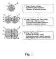
- the present invention takes advantage of a spatial oxidation expansion, which a deposited material 4 may undergo during an oxidation process.
- the spatial oxidation expansion may be broken down into three stages. During a first stage of sole oxygen diffusion, the grains 2 expand substantially symmetric during oxidation of the deposited material 4 . Symmetric spatial expansion takes place as long as the expansion remains physically uninhibited. Oxidized material 5 begins to progress from the grain boundary 6 towards the grain center continuously replacing the deposited material 4 .
- a second stage including a mass transfer is initiated.
- an asymmetric spatial expansion takes place while the oxidation of the deposited material 4 continues towards the grain centers.
- the asymmetric spatial expansion stems from the restricted expansion in the grain interface 7 between the adjacent grains 2 .
- eventual voids and pores between adjacent grains 2 are filled with the expanding oxidized material. Voids and pores are likely resulting from initial deposition of the grains 2 .
- a spatial oxidation expansion ratio between the unoxidized material and the oxidized material may be readily predetermined in a well-known fashion.
- the spatial oxidation expansion ratio is 1.45.
- the in plane portion of the spatial oxidation expansion ratio may calculated as the second power of the third root of the spatial oxidation expansion ratio.
- the in-plane oxidation expansion ratio for unoxidized Aluminum to oxidized Alpha Alumina is about 1.178.
- the in-plane oxidation expansion ratio for unoxidized 85/15 Zirconium/Yttrium alloy to yttria stabilized zirconia is about 1.131.
- an in-plane deposition density of the deposited material may be at least the invert of the in-plane oxidation expansion ratio.
- in-plane deposition density refers to the average ratio between voids and deposited grains 2 across a deposition height the deposited grains 2.
- the deposition density for unoxidized aluminum may be at least about 0.849 and for unoxidized 85/15 Zirconium/Yttrium alloy at least about 0.78.
- the three-stage oxidization is preferably performed at temperatures well above an operational temperature of the finally fabricated continuous film.
- An oxidization temperature is selected such that the deposited material and/or the oxidized material is/are in a condition of increased plasticity.
- the increased plasticity in turn is important for the mass transfer.
- YSZ is oxidized preferably at temperatures between 300° ⁇ 400°C.
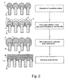
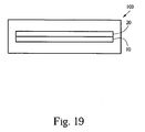
- Fig. 2 illustrates the application of the three-stage oxidization in fabrication of a continuous film 20 on top of a porous substrate 10.
- the schematic on the left side of Fig. 2 depicts a simplified frontal cut view through the porous substrate 10 with three stage oxidation and a final heat treatment step.
- the material 4 is deposited in a substantially unoxidized condition on top of the solid portion of the porous substrate 10.
- a preferred deposition material may be a metal and a preferred deposition technique may be a well-known DC-magnetron sputtering.
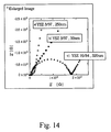
- the porous substrate 10 may be, for example a 200nm-type Gamma Alumina substrate with vertically protruding pores having a diameter between 150 - 200nm (see Fig. 4 ).
- the 200nm-type porous substrate may have a void/solid ratio of about 9/1, which means that about 10% of the porous substrate's 10 top are solid and the remaining about 90% of the porous substrate's 10 top are open.
- the porous substrate 10 may also be, for example a 20nm-type Gamma Alumina substrate with vertically protruding pores having a diameter between 80 - 200nm (see Fig. 5 ).
- the 20nm-type porous substrate may have a void/solid ratio of about 1/1, which means that about 50% of the porous substrate's 10 top are solid and the remaining about 50% of the porous substrate's 10 top are open.
- Porous substrate 10 made from Gamma Alumina may be commercially available under the tradename Anodisc®.
- the initial deposition step is adjusted to provide the required deposition density while keeping the deposition height to a minimum.
- deposition density becomes more challenging to accomplish for a targeted deposition thickness.
- To deposit Aluminum on a 200nm type porous substrate 10 with required deposition density about 11.8% of the deposited material 4 is directly supported by the solid portion of the porous substrate 10. This example is solely presented for the purpose of general understanding of the structure considerations that exist for optimized deposition of material 4 on top of the porous substrate 10.
- deposition thickness may be minimized by adjustment of deposition parameters, such as for example, sputtering angle and/or kinetic energies of the sputtered material.
- the three stage oxidation is performed as described under Fig. 1 resulting in a void free film.
- the void free film is heat treated for recombining the oxidized grains along the grain boundaries 6.
- the heat treatment process may be utilized to smoothen the top surface 23 of the continuous film 20. Heat may be applied as directional radiation heat and/or as convective heat. Heat treatment is preferably accomplished in a furnace.
- the heat treatment step may be performed at the same and/or different temperature or atmospheric settings than applied during oxidation. Nevertheless, oxidation and heat treatment may overlap, since grain recombination may take place as soon as adjacent grain boundaries 6 expand into contact.
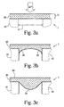
- Figs. 3a, 3b operational structure considerations for minimizing the height 21 of the continuous film are described in more detail.
- operational structure considerations relate to the minimum continuous film structure required for a given porous substrate 10 and mechanical operation conditions to which the continuous film 20 may be exposed.
- the simplest case is depicted in Fig. 3a in which the continuous thin film 21 is a substantially equally thick layer.
- a minimum for the film thickness 21 may be calculated by the following equations.
- the minimum film thickness for sample A (pore size: 20nm, ⁇ P: 0.1MPa) estimated with the reported mechanical properties of commercial 99.9% bulk alumina ceramics is 0.15nm.
- pore size 20nm, ⁇ P: 0.1MPa
- the reasonable minimum thickness might be larger than the estimation. Nevertheless, the estimated thickness limit is key reference for practical optimization of the continuous film 20.
- Fig. 3b the bottom portion 22 of the continuous film 20 may have a concave curvature eventually resulting from a shrinkage during cooling of the continuous film 20 after heat treatment.
- the film may attach laterally at the sidewalls of the substrate's 10 pores. Lateral attachment may be result from the deposition process and/or from the oxidation expansion.
- the bottom portion 24 may have a convex curvature eventually resulting from an excess vertical expansion.
- Such excess vertical expansion may result from a deposition density significantly above the required deposition density where voids and/or pores are filled significantly before the oxidation expansion is completed.
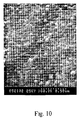
- the enlarged picture of Fig. 10 shows such a case.
- porous substrates 10 commercial inorganic alumina filters (Anodisc®, Whatman Inc.) with a pore size of 20nm and 200nm were used.
- the terms "20nm type” and "200nm type” relates to terminology used by the producer with respect to the filtering ability of their respective product.
- the observed actual pore diameters by SEM were 80nm - 200nm for 20nm-type filters and 150nm - 300nm for 200nm-type filters.
- the filter diameter (without support ring) was 40mm, filter thickness was 60 ⁇ m and maximum working pressure was about 0.52MPa.
- An Aluminum target with 99.999% purity and a Y-Zr complex target consisting of three or four 5mm ⁇ 5mm ⁇ 1mm-sized Y pellets with 99.9% purity on a Zr target with 99.7% purity were used for metal film deposition using DC-magnetron sputtering.
- the Ar gas flow rate was 10sccm and Ar pressure wasl.2Pa at 50W for aluminum deposition and 10sccm - 30sccm, 1.2Pa - 2.8Pa at 30W for Y-Zr deposition.
- the Y/Zr composition was determined by X-ray photoemission spectroscopy (SSI S-Probe Monochromatized XPS Spectrometer). All samples where oxidized at 700 °C for two hours. The composition of the Y/Zr samples had a purity of higher than 99.7%. The microstructure of the thin films was observed with SEM. The phase development of sample A including a separate heat-treating step at 400°C ⁇ 1300°C for 2hours was observed using XRD as is described in the following. Table 2 Mat.
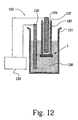
- the samples obtained were tested in a test setup illustrated in Fig. 12 .
- a sample 1 was fixed with polymer adhesives to a thick silicone tube 125 filled with hydrogen 127 , and then immersed in NaCl-water solution 126 to measure hydrogen permeance through oxidized thin films 20 .
- the hydrogen pressure ( ⁇ P) used was 0.1MPa.
- Ionic conductivity of oxidized Y-Zr films was measured from nyquist plots obtained using 0.03N NaCl-water solution 126 as electrodes with Solartron 1260/1287 impedance analyzer 122 at room temperature.
- FIGs. 4 and 5 SEM images of the Anodisc® substrates having of 200nm-type and 20nm-type are shown. The pores are columnar and penetrate through the porous substrates 10 .
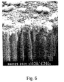
- Fig. 6 shows the surface and fractured edge after deposition of unoxidized aluminum on the porous substrate 10 . Even though the deposited film thickness is only about 200nm, it already covers the whole surface showing smooth and grain-like aggregated metal islands. There are also flake-shaped particles on the metal surface suggesting that impurities existed and worked as nuclei for aggregation of metal atoms during sputtering. A continuous film 20 of oxidized Aluminum was obtained from the deposited film of Fig. 6 after heat-treated at 700°C for 2hours.
- the continuous film 20 displayed a homogeneous surface covering pores of substrates without cracks or pinholes.
- the oxidized Aluminum film 20 may be utilized as a membrane where ionic conductivity is irrelevant.
- the Aluminum sample where primarily fabricated and tested for fluid impermeability and fabrication feasibility.
- Fluid impermeability was tested in a hydrogen permeation test in which the hydrogen permeance was measured at 0.1MPa. The results are depicted in Fig. 11a .
- the permeance for sample B (column (a) ) is 6.40 ⁇ 10 -6 mol/m 2 ⁇ s ⁇ Pa and slightly decreased to 1.97 ⁇ 10 -6 mol/m 2 ⁇ s ⁇ Pa by heat-treatment at 700°C for 2hours (column (b) ). This may be due to change of the dimension of columns by shrinkage during heat-treatment.
- the permeance for sample B (with a thin film, column (c) ) drastically decreased to 2.01 ⁇ 10 -9 mol/m 2 ⁇ s ⁇ Pa.
- the permeances measured for the sample A are reflected in colums (d) , (e) and (f). They show smaller values than those of (a), (b) and (c) due to their smaller pore size.
- the gas permeance for sample A (column (f) ) could not be detected with the present measurement settings and thus the measurable minimum permeance of 7.44 ⁇ 10 -11 mol/m 2 ⁇ s ⁇ Pa is assigned for column (f) .
- Fabrication feasibility of continuous films 20 is strongly influenced by the deposited material's 4 oxidation behavior and phase development.
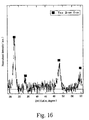
- phase development during oxidation of the thin films of samples A, B XRD patterns at various oxidation stages and during the heat-treatment were obtained. No distinct crystalline peak was observed until the temperature reaches 900°C. However, the color of thin film changed from metal silver to glassy transparent at 500°C. At 900°C, theta-alumina phase was detected and the peak intensity increased with increasing temperature. At 1300°C well-developed theta phase was observed. However, several peaks of alpha phase were also detected in the pattern of 1300°C.
- the collected patterns were strongly affected by the substrate 10 and show both phases of thin film 20 and substrate 10 .
- the XRD pattern was compared with that of a bare substrate 10 heated at 1300°C for 2hours. The comparison clearly showed that only the pattern from thin film showed alpha phase even though the peak intensity was small compared to that of bare substrate.
- the relative peak intensity estimated from the fitted alpha phase peaks matched well with the relative intensity from reported data for bulk polycrystalline alpha-alumina
- Aluminum 20 deposited with a height of about 30nm oxidizes around 500°C and transforms to alpha phase between 1000°C ⁇ 1300°C. Otherwise, the substrate 10 has amorphous phase up to 700°C and then transforms to theta-form at 800°C.
- the protective oxide layer formed on the surface of aluminum and low oxygen diffusivity may be responsible for the high crystallization temperature observed. It was found that aluminum film with a thickness of 200nm was not fully oxidized after 10 hours of heat-treatment at 700°C, while clear single YSZ phase was easily achieved from oxidized Y-Zr alloy deposited with a height of about 200nm and heat-treated at 700°C for 2hour.
- continuous films 20 made of deposited Y/Zr alloy are now described in detail.
- a Y/Zr alloy deposited with a thickness of about 50nm displayed in an SEM photography a silver-colored smooth surface without pores or voids being detected.
- the actual deposition density of the samples C - H was above the required deposition density. Consequently and as depicted in Fig. 10 , the bottom of the derived continuous film 20 appeared similar to the bottom of Fig. 3c .
- sample E displayed a continuous film 20 without any cracks and pinholes appeared on the porous substrate 10 .
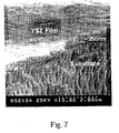
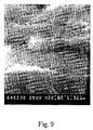
- Sample H is shown in Figs. 8 and 9 .
- Fig. 8 shows the film top 23
- the surface was not smooth and many large island-shaped grains were found.
- sample H showed good fluid-separation, the rough surface may limit achievable minimum film thickness.
- the inhomogeneous surface could be due to the high Ar pressure to retain plasma on the complex target surface with the high contact resistance between Y-pellet and Zr target.
- Fig. 10 shows the backside-view of the continuous film 20 of Sample E that was in contact with the 20nm-type substrate 10 .
- the substrate 10 was etched out with 1N-NaOH solution.
- the bottom side 24 was different from the top surface 23 of the same sample E.
- the bottom side displayed circle-shaped islands with diameter ranging from 50nm to 120nm on the whole surface, suggesting that the thin film covering the top of the substrate's 10 pores was swallowed into the pores.
- Fluid impermeability was tested in a hydrogen permeation test in which the hydrogen permeance was measured for the oxidized Y-Zr thin films 20 at 0.1MPa hydrogen pressure.
- the results are illustrated in Fig. 11 b.
- the permeance of the substrate 10 without heating (column (a) for 200nm-type substrate 10 and column (e) for 20nm-type substrate 10 ) and with heating at 700°C for 2h (column (b) , for 200nm-type substrate 10 and column (f) for 20nm-type substrate 10 ) are again shown for comparison.
- the permeance for sample D (column (c) ) slightly decreased to 7.49 ⁇ 10 -7 mol/m 2 ⁇ s ⁇ Pa.
- the continuous thin film 20 of sample D did not demonstrate sufficient fluid-separation compared to the low permeance value in the 35nm-thick Alumina thin film on 200nm-type substrate 10.
- the permeance for the sample F (column (d) ) dropped to 7.44 ⁇ 10 -11 mol/m 2 ⁇ s ⁇ Pa, which was below the measuring limit.
- the 250nm-thick film 20 on 20nm-pore-sized substrate 10 is enough to work as a gas separation layer. That is, the thickness of 50nm deposited with DC-magnetron sputtering in a substantially perpendicular deposition direction was insufficient to form a continuous film 20 across the pores of the 200nm-type porous substrate 10 .
- the crystalline YSZ could be easily obtained by oxidation at 500°C ⁇ 700°C, a quite lower temperature than Alumina thin film. Oxidation of the deposited Y/Zr alloy material 4 occurs at very low temperatures in a relatively short period compared to deposited Alumina material 4 . As a favorable result, the inventive process has also significance as a low-temperature processing for oxide thin films, besides its preferred application for fabricating ultra-thin film with nano-size conductivity effects as described in more detail in the below.
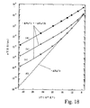
- Fig. 17 is a reference graph suggested in the prior art based on the fast oxygen diffusion through grain boundaries and its large contribution to lower the activation energy ( ⁇ H) for oxygen ionic conduction. Since the ionic conductivity term ( ⁇ ) is proportional to exp(- ⁇ H/kT), the contribution of lowered ⁇ H to ⁇ exponentially increases with a decrease of temperature.
- ⁇ H for sample H possibly is in the range of 0.18eV to 0.47eV, which is much smaller than 1.02eV ( Fig. 15(e) ). That is, if the estimated ⁇ H value of 0.18eV is exact and the activation energy for the defect-free YSZ is exactly the same as that of the grains in the obtained thin films 20 , defect density should be the only variable to change the absolute conductivity.
- the bending Arrhenius plot at low temperature and change of the absolute conductivity can be simulated with a model with edge dislocations.
- the estimation performed for a dislocation effect on the conductivity at low temperature can be one of reasonable explanations for the extraordinary increase of ionic conductivity at low temperature, especially in thin films 20 with nanometer-sized grains 2 , which contain a large volume fraction of grain boundaries 6 .
- Parasitic capacitances may build up where ions eventually have to bridge across adjacent grain boundaries 6 perpendicularly oriented to the ions' path from one thin film surface to the opposing surface.
- grain boundaries 6 extend substantially continuously from surface-to-surface and provide highly conductive pathways substantially free of parasitic capacitances.
- the experimental results suggest that heat treatment following oxidation may be adjusted to tune recombination of grain boundaries 6 for an optimized balance between low temperature ion conductivity and fluid impermeability.
- porous substrates 10 such as porous silicon may be used with deposition materials 4 that exhibit oxidation expansion.
- other well-known ceramic material with suitable ionic conductivity may be fabricated in a fashion similar as described in the above for YSZ. Such ceramic may be for example, gadolinium doped ceria.
- Ionic conductivity of the continuous film 20 may be further improved by fabricating continuous surface-to-surface dislocations into the continuous film 20 .
- continuous surface-to-surface dislocations into the continuous film 20 .
- the porous substrate 10 may be made electrically conductive in a well-known fashion like, for example through electroplating and/or doping.
- the porous substrate 10 may also be a metallic substrate.
Landscapes
- Chemical & Material Sciences (AREA)
- Engineering & Computer Science (AREA)
- Manufacturing & Machinery (AREA)
- Ceramic Engineering (AREA)
- Life Sciences & Earth Sciences (AREA)
- Chemical Kinetics & Catalysis (AREA)
- Electrochemistry (AREA)
- General Chemical & Material Sciences (AREA)
- Materials Engineering (AREA)
- Sustainable Energy (AREA)
- Organic Chemistry (AREA)
- Sustainable Development (AREA)
- Structural Engineering (AREA)
- Health & Medical Sciences (AREA)
- General Physics & Mathematics (AREA)
- Immunology (AREA)
- Physics & Mathematics (AREA)
- Analytical Chemistry (AREA)
- Biochemistry (AREA)
- General Health & Medical Sciences (AREA)
- Molecular Biology (AREA)
- Pathology (AREA)
- Composite Materials (AREA)
- Fuel Cell (AREA)
- Measuring Oxygen Concentration In Cells (AREA)
- Conductive Materials (AREA)
- Application Of Or Painting With Fluid Materials (AREA)
- Compositions Of Oxide Ceramics (AREA)
- Inert Electrodes (AREA)
Claims (11)
- Procédé de fabrication d'un film continu sur un substrat poreux, ledit procédé comprenant les étapes suivantes :a. sélection d'une matière de dépôt ayant un rapport de dilatation à l'oxydation, dans laquelle une partie dans le plan du rapport de dilatation à l'oxydation est égale à la puissance carrée de la racine cubique du rapport de dilatation ;b. dépôt de ladite matière de dépôt selon une hauteur de dépôt et une densité de dépôt par-dessus ledit substrat, ladite matière de dépôt étant en un état non oxydé ;c. oxydation de ladite matière de dépôt par-dessus ledit substrat, ladite matière de dépôt étant convertie en une matière oxydée dilatée spatialement par rapport à ladite matière de dépôt, ladite densité de dépôt étant supérieure ou égale à l'inverse de ladite partie dans le plan du rapport de dilatation,
dans lequel ladite hauteur de dépôt et ladite densité de dépôt sont sélectionnées conjointement avec ladite dilatation d'oxydation spatiale de telle sorte que durant ladite oxydation un film dépourvu de vides soit formé par-dessus ledit substrat ;
etd. traitement thermique dudit film dépourvu de vides afin de recombiner ladite matière oxydée dans ledit film continu. - Procédé selon la revendication 1, dans lequel ladite matière de dépôt est sélectionnée de telle sorte qu'après ladite oxydation, ladite matière oxydée soit un électrolyte à conduction ionique et de telle sorte que ledit film continu soit imperméable aux fluides.
- Procédé selon la revendication 2, dans lequel ladite matière de dépôt est de la zircone stabilisée à l'yttria.
- Procédé selon la revendication 1, dans lequel ledit substrat poreux est réalisé en un oxyde.
- Procédé selon la revendication 4, dans lequel ledit substrat poreux est réalisé en oxyde d'aluminium anodisé.
- Procédé selon la revendication 1, dans lequel ledit dessus dudit substrat poreux présente des pores d'un diamètre inférieur à 200 nm, ledit film continu ayant une épaisseur de moins de 1µm et une perméabilité à l'hydrogène de moins de 10-10 mol/m2 sPa à température ambiante.
- Procédé selon la revendication 1, dans lequel ledit film continu a une perméabilité à l'hydrogène de moins de 10-10 mol/m2sPa à température ambiante et une résistance locale ionique de moins de 200 ohms à une température de 250°C pour une épaisseur dudit film continu de 1 µm, ledit film continu étant réalisé en zircone stabilisée à l'yttria.
- Procédé selon la revendication 1, dans lequel ledit film continu est une membrane d'électrolyte pour pile à combustible.
- Procédé selon la revendication 1, dans lequel ledit film continu est une membrane d'électrolyte de pile à combustible.
- Procédé selon la revendication 1, dans lequel ledit dépôt est effectué par pulvérisation magnétron C.C..
- Procédé selon la revendication 1, dans lequel ledit substrat poreux comporte des pores d'un diamètre entre 80 nm et 200 nm avant ledit traitement thermique.
Applications Claiming Priority (5)
| Application Number | Priority Date | Filing Date | Title |
|---|---|---|---|
| US38438002P | 2002-05-29 | 2002-05-29 | |
| US38437802P | 2002-05-29 | 2002-05-29 | |
| US384378P | 2002-05-29 | ||
| US384380P | 2002-05-29 | ||
| PCT/US2003/017202 WO2003101629A1 (fr) | 2002-05-29 | 2003-05-29 | Film mince electrolytique submicronique forme sur un substrat nanoporeux par oxydation d'un film metallique |
Publications (3)
| Publication Number | Publication Date |
|---|---|
| EP1513623A1 EP1513623A1 (fr) | 2005-03-16 |
| EP1513623A4 EP1513623A4 (fr) | 2007-08-08 |
| EP1513623B1 true EP1513623B1 (fr) | 2012-09-12 |
Family
ID=29715326
Family Applications (2)
| Application Number | Title | Priority Date | Filing Date |
|---|---|---|---|
| EP03739011A Expired - Lifetime EP1513623B1 (fr) | 2002-05-29 | 2003-05-29 | Film mince electrolytique submicronique forme sur un substrat nanoporeux par oxydation d'un film metallique |
| EP03808387A Withdrawn EP1514323A4 (fr) | 2002-05-29 | 2003-05-29 | Electrolyte a oxyde solide presentant une amelioration au niveau de la conductivite ionique, par dislocation |
Family Applications After (1)
| Application Number | Title | Priority Date | Filing Date |
|---|---|---|---|
| EP03808387A Withdrawn EP1514323A4 (fr) | 2002-05-29 | 2003-05-29 | Electrolyte a oxyde solide presentant une amelioration au niveau de la conductivite ionique, par dislocation |
Country Status (7)
| Country | Link |
|---|---|
| US (2) | US7179500B2 (fr) |
| EP (2) | EP1513623B1 (fr) |
| JP (2) | JP4216803B2 (fr) |
| KR (1) | KR20050013108A (fr) |
| AU (2) | AU2003301727A1 (fr) |
| CA (2) | CA2487859A1 (fr) |
| WO (2) | WO2004040670A2 (fr) |
Cited By (1)
| Publication number | Priority date | Publication date | Assignee | Title |
|---|---|---|---|---|
| DE102013008472A1 (de) | 2013-05-21 | 2014-11-27 | Plansee Composite Materials Gmbh | Mehrlagige Schichtanordnung für einen Festkörperelektrolyt |
Families Citing this family (31)
| Publication number | Priority date | Publication date | Assignee | Title |
|---|---|---|---|---|
| US7108813B2 (en) * | 2004-03-30 | 2006-09-19 | The Board Of Trustees Of The Leland Stanford Junior University | Gas/ion species selective membrane supported by multi-stage nano-hole array metal structure |
| US20060008696A1 (en) * | 2004-06-30 | 2006-01-12 | Suk-Won Cha | Nanotubular solid oxide fuel cell |
| US7655333B2 (en) * | 2004-06-30 | 2010-02-02 | The Board Of Trustees Of The Leland Stanford Junior University | Sub-micron solid oxide electrolyte membrane in a fuel cell |
| US20060189142A1 (en) * | 2004-06-30 | 2006-08-24 | Yuji Saito | Method for making a sub-micron solid oxide electrolyte membrane |
| JP4701695B2 (ja) * | 2004-12-08 | 2011-06-15 | トヨタ自動車株式会社 | 固体電解質およびその製造方法 |
| JP5172076B2 (ja) * | 2005-03-18 | 2013-03-27 | 株式会社ニッカトー | 高導電性ジルコニア質焼結体 |
| US7455722B2 (en) * | 2005-07-26 | 2008-11-25 | Honda Motor Co., Ltd | Ion irradiated electrolyte membrane, anode, and/or cathode |
| CN1737846B (zh) * | 2005-09-02 | 2012-02-22 | 上海高智科技发展有限公司 | 一种从电子出版物在线网络平台获取在线电子出版物的方法 |
| US20070072046A1 (en) * | 2005-09-26 | 2007-03-29 | General Electric Company | Electrochemcial cell structures and methods of making the same |
| US7807231B2 (en) * | 2005-11-30 | 2010-10-05 | General Electric Company | Process for forming thermal barrier coating resistant to infiltration |
| TWI295102B (en) * | 2006-01-13 | 2008-03-21 | Ind Tech Res Inst | Multi-functional substrate structure |
| WO2007121032A2 (fr) | 2006-03-23 | 2007-10-25 | The Research Foundation Of State University Of New York | Procédés et systèmes optiques de détection d'un constituant dans un gaz contenant de l'oxygène dans des conditions difficiles |
| US20130332945A1 (en) * | 2006-05-09 | 2013-12-12 | Shanghai Gaozhi Science And Technology Development Co. Ltd | Method for establishing a network platform for renting the electronic publications |
| US20080216132A1 (en) * | 2006-05-09 | 2008-09-04 | Shanghai Gaozhi Science And Technology Development Co., Ltd. | Method for establishing a network platform for renting the electronic publications |
| JP5198000B2 (ja) * | 2006-09-14 | 2013-05-15 | 本田技研工業株式会社 | 電解質・電極接合体及びその製造方法 |
| US20080085430A1 (en) * | 2006-10-10 | 2008-04-10 | Macbain John A | Battery integration and control in an auxiliary power unit powered by a solid oxide fuel cell system |
| US20100255387A1 (en) * | 2006-12-27 | 2010-10-07 | President And Fellows Of Harvard College | Photo-activation of solid oxide fuel cells and gas separation devices |
| US8623301B1 (en) | 2008-04-09 | 2014-01-07 | C3 International, Llc | Solid oxide fuel cells, electrolyzers, and sensors, and methods of making and using the same |
| JP5231080B2 (ja) * | 2008-04-30 | 2013-07-10 | 行政院原子能委員會核能研究所 | スパッタリング法による高性能固体酸化物形燃料電池膜電極接合体(sofc−mea)の電解質層の製造方法。 |
| WO2010077945A2 (fr) | 2008-12-17 | 2010-07-08 | Saint-Gobain Ceramics & Plastics, Inc. | Electrolytes ysz co-dopés pour empilements de piles à combustible à oxyde solide |
| KR101034706B1 (ko) | 2009-06-15 | 2011-05-17 | 한국생산기술연구원 | 고체산화물 연료전지의 전해질 복합체 및 그 제조방법 |
| CA2789281C (fr) | 2010-02-10 | 2015-11-24 | C3 International, Llc | Electrolytes fonctionnant a basse temperature pour piles a oxyde solide presentant une conductivite ionique elevee |
| JP2013179037A (ja) * | 2012-01-31 | 2013-09-09 | Nissan Motor Co Ltd | 燃料電池用電解質、固体酸化物形燃料電池及びその製造方法 |
| US9905871B2 (en) | 2013-07-15 | 2018-02-27 | Fcet, Inc. | Low temperature solid oxide cells |
| FR3009217B1 (fr) * | 2013-08-01 | 2016-10-28 | Quertech | Procede de traitement de poudre a base d'oxyde de cerium |
| US11667576B2 (en) * | 2019-03-08 | 2023-06-06 | Purdue Research Foundation | Methods of enhancing the deformability of ceramic materials and ceramic materials made thereby |
| KR20210102738A (ko) * | 2020-02-12 | 2021-08-20 | 삼성전자주식회사 | 복합 고체전해질, 그 제조방법 및 이를 포함하는 전기화학전지 |
| CN112768704B (zh) * | 2021-01-12 | 2023-05-26 | 万华化学(四川)有限公司 | 一种基于质子传导型电解质的固态氧化物燃料电池及制备方法 |
| DE102021130349A1 (de) | 2021-03-12 | 2022-09-15 | Technische Universität Darmstadt, Körperschaft des öffentlichen Rechts | Verfahren und Vorrichtung zur Herstellung von Keramiken und keramisches Produkt |
| KR102624426B1 (ko) * | 2021-10-27 | 2024-01-12 | 한국표준과학연구원 | 가스 투과 측정용 표준 재료 |
| JP2025031193A (ja) * | 2023-08-25 | 2025-03-07 | 株式会社日立製作所 | 固体酸化物型燃料電池およびその製造方法 |
Family Cites Families (36)
| Publication number | Priority date | Publication date | Assignee | Title |
|---|---|---|---|---|
| US3348A (en) * | 1843-11-21 | Horatio allen | ||
| US4069068A (en) * | 1976-07-02 | 1978-01-17 | International Business Machines Corporation | Semiconductor fabrication method for improved device yield by minimizing pipes between common conductivity type regions |
| US4839019A (en) * | 1986-11-20 | 1989-06-13 | Fuji Electric Co., Ltd. | Oxygen sensor |
| US4851303A (en) * | 1986-11-26 | 1989-07-25 | Sri-International | Solid compositions for fuel cells, sensors and catalysts |
| US4764491A (en) * | 1987-05-11 | 1988-08-16 | General Motors Corporation | Low temperature sintering of yttria stabilized zirconia with lanthana borate additions |
| US5310575A (en) | 1987-11-03 | 1994-05-10 | Robert Bosch Gmbh | Method of making a porous ceramic protective layer on an electrode of an electrochemical sensor for exposure to hot gas |
| JPH02181367A (ja) * | 1989-01-06 | 1990-07-16 | Yamaha Motor Co Ltd | 燃料電池用セパレータとその製造方法 |
| US4888114A (en) * | 1989-02-10 | 1989-12-19 | E. I. Du Pont De Nemours And Company | Sintered coating for porous metallic filter surfaces |
| JPH02242566A (ja) * | 1989-03-15 | 1990-09-26 | Sanyo Electric Co Ltd | 固体電解質燃料電池 |
| JPH0364087A (ja) * | 1989-08-02 | 1991-03-19 | Mitsubishi Electric Corp | 半導体レーザ装置およびその製造方法 |
| US5130210A (en) * | 1989-08-25 | 1992-07-14 | Tonen Corporation | Stabilized zirconia solid electrolyte and process for preparation thereof |
| JPH0821255B2 (ja) * | 1990-04-16 | 1996-03-04 | 松下電器産業株式会社 | 薄膜固体電解質の製造方法 |
| US5106654A (en) * | 1990-07-20 | 1992-04-21 | Westinghouse Electric Corp. | Method of forming a dense, high temperature electronically conductive composite layer on a porous ceramic substrate |
| GB9025236D0 (en) | 1990-11-20 | 1991-01-02 | Secr Defence | Silicon-on porous-silicon;method of production |
| DE4117284A1 (de) * | 1991-05-27 | 1992-12-03 | Studiengesellschaft Kohle Mbh | Verfahren zur herstellung von mikroporoesen keramikmembranen fuer die trennung von gas- und fluessigkeitsgemischen |
| US5344549A (en) * | 1991-10-11 | 1994-09-06 | The United States Of America As Represented By The United States Department Of Energy | Oxygen partial pressure sensor |
| US5160618A (en) * | 1992-01-02 | 1992-11-03 | Air Products And Chemicals, Inc. | Method for manufacturing ultrathin inorganic membranes |
| US5360635A (en) * | 1992-01-02 | 1994-11-01 | Air Products And Chemicals, Inc. | Method for manufacturing inorganic membranes by organometallic chemical vapor deposition |
| JPH06283178A (ja) * | 1993-03-29 | 1994-10-07 | Nippon Telegr & Teleph Corp <Ntt> | 固体電解質型燃料電池の電解質膜製造方法 |
| JP3333325B2 (ja) * | 1993-08-26 | 2002-10-15 | 株式会社東芝 | 半導体装置、半導体装置のシミュレーション方法、及び半導体装置のシミュレータ |
| US5415891A (en) * | 1994-01-10 | 1995-05-16 | Media And Process Technology Inc. | Method for forming metal-oxide-modified porous ceramic membranes |
| US5534471A (en) * | 1994-01-12 | 1996-07-09 | Air Products And Chemicals, Inc. | Ion transport membranes with catalyzed mixed conducting porous layer |
| US5871650A (en) * | 1994-07-08 | 1999-02-16 | Exxon Research And Engineering Company | Supported zeolite membranes with controlled crystal width and preferred orientation grown on a growth enhancing layer |
| US5681373A (en) * | 1995-03-13 | 1997-10-28 | Air Products And Chemicals, Inc. | Planar solid-state membrane module |
| JPH08293310A (ja) * | 1995-04-20 | 1996-11-05 | Tokyo Gas Co Ltd | 固体電解質膜の製造方法 |
| KR0158431B1 (ko) * | 1995-06-23 | 1998-11-16 | 윤덕용 | 수소분리용 무기재료막의 제조방법 |
| EP0763864A1 (fr) * | 1995-09-13 | 1997-03-19 | Kabushiki Kaisha Meidensha | Pile à combustible à électrolyte solide fonctionnant à haute température |
| US5753385A (en) | 1995-12-12 | 1998-05-19 | Regents Of The University Of California | Hybrid deposition of thin film solid oxide fuel cells and electrolyzers |
| US6152987A (en) * | 1997-12-15 | 2000-11-28 | Worcester Polytechnic Institute | Hydrogen gas-extraction module and method of fabrication |
| US6251473B1 (en) * | 1999-05-12 | 2001-06-26 | The Trustees Of The University Of Pennsylvania | Preparation of ceramic thin films by spray coating |
| US6465365B1 (en) * | 2000-04-07 | 2002-10-15 | Koninklijke Philips Electronics N.V. | Method of improving adhesion of cap oxide to nanoporous silica for integrated circuit fabrication |
| US6514881B1 (en) * | 2000-05-23 | 2003-02-04 | Texas Instruments Incorporated | Hybrid porous low-K dielectrics for integrated circuits |
| US6437375B1 (en) | 2000-06-05 | 2002-08-20 | Micron Technology, Inc. | PD-SOI substrate with suppressed floating body effect and method for its fabrication |
| US6432308B1 (en) * | 2000-09-25 | 2002-08-13 | Graver Technologies, Inc. | Filter element with porous nickel-based alloy substrate and metal oxide membrane |
| AU2002357341A1 (en) * | 2001-12-18 | 2003-06-30 | The Regents Of The University Of California | A process for making dense thin films |
| US20030003348A1 (en) | 2002-07-17 | 2003-01-02 | Hanket Gregory M. | Fuel cell |
-
2003
- 2003-05-29 EP EP03739011A patent/EP1513623B1/fr not_active Expired - Lifetime
- 2003-05-29 WO PCT/US2003/017432 patent/WO2004040670A2/fr not_active Ceased
- 2003-05-29 WO PCT/US2003/017202 patent/WO2003101629A1/fr not_active Ceased
- 2003-05-29 EP EP03808387A patent/EP1514323A4/fr not_active Withdrawn
- 2003-05-29 AU AU2003301727A patent/AU2003301727A1/en not_active Abandoned
- 2003-05-29 JP JP2004508971A patent/JP4216803B2/ja not_active Expired - Fee Related
- 2003-05-29 US US10/449,736 patent/US7179500B2/en not_active Expired - Fee Related
- 2003-05-29 CA CA002487859A patent/CA2487859A1/fr not_active Abandoned
- 2003-05-29 KR KR10-2004-7018992A patent/KR20050013108A/ko not_active Ceased
- 2003-05-29 AU AU2003245372A patent/AU2003245372A1/en not_active Abandoned
- 2003-05-29 US US10/449,709 patent/US7195833B2/en not_active Expired - Fee Related
- 2003-05-29 JP JP2004548275A patent/JP2006501626A/ja active Pending
- 2003-05-29 CA CA2487611A patent/CA2487611C/fr not_active Expired - Fee Related
Cited By (2)
| Publication number | Priority date | Publication date | Assignee | Title |
|---|---|---|---|---|
| DE102013008472A1 (de) | 2013-05-21 | 2014-11-27 | Plansee Composite Materials Gmbh | Mehrlagige Schichtanordnung für einen Festkörperelektrolyt |
| US10312540B2 (en) | 2013-05-21 | 2019-06-04 | Plansee Composite Materials Gmbh | Multi-layered layer arrangement for a solid electrolyte |
Also Published As
| Publication number | Publication date |
|---|---|
| CA2487859A1 (fr) | 2004-05-13 |
| EP1513623A1 (fr) | 2005-03-16 |
| JP2006501626A (ja) | 2006-01-12 |
| US7195833B2 (en) | 2007-03-27 |
| KR20050013108A (ko) | 2005-02-02 |
| JP2005527370A (ja) | 2005-09-15 |
| AU2003301727A1 (en) | 2004-05-25 |
| EP1513623A4 (fr) | 2007-08-08 |
| EP1514323A2 (fr) | 2005-03-16 |
| WO2003101629A1 (fr) | 2003-12-11 |
| AU2003245372A1 (en) | 2003-12-19 |
| US20040013924A1 (en) | 2004-01-22 |
| CA2487611A1 (fr) | 2003-12-11 |
| CA2487611C (fr) | 2011-11-01 |
| US20040038106A1 (en) | 2004-02-26 |
| EP1514323A4 (fr) | 2006-01-11 |
| AU2003301727A8 (en) | 2004-05-25 |
| US7179500B2 (en) | 2007-02-20 |
| WO2004040670A2 (fr) | 2004-05-13 |
| JP4216803B2 (ja) | 2009-01-28 |
| AU2003245372A8 (en) | 2003-12-19 |
| WO2004040670A3 (fr) | 2004-10-21 |
Similar Documents
| Publication | Publication Date | Title |
|---|---|---|
| EP1513623B1 (fr) | Film mince electrolytique submicronique forme sur un substrat nanoporeux par oxydation d'un film metallique | |
| Waldbillig et al. | Electrochemical and microstructural characterization of the redox tolerance of solid oxide fuel cell anodes | |
| Garbayo et al. | Porous La0. 6Sr0. 4CoO3− δ thin film cathodes for large area micro solid oxide fuel cell power generators | |
| Yang et al. | Low temperature solid oxide fuel cells with pulsed laser deposited bi-layer electrolyte | |
| Park et al. | Effect of the thickness of sputtered gadolinia-doped ceria as a cathodic interlayer in solid oxide fuel cells | |
| Cho et al. | Multi-component nano-composite electrode for SOFCS via thin film technique | |
| EP3330403A1 (fr) | Complexe de film d'oxyde composite de type apatite orienté/substrat et procédé permettant de produire ce dernier | |
| Ko et al. | Ultra-thin film solid oxide fuel cells utilizing un-doped nanostructured zirconia electrolytes | |
| Joo et al. | Open-circuit voltage of ceria-based thin film SOFC supported on nano-porous alumina | |
| Lalanne et al. | Intermediate temperature SOFC single cell test using Nd1. 95NiO4+ δ as cathode | |
| JP2003059523A (ja) | 固体電解質型燃料電池 | |
| Park et al. | Thin-film SOFCs using gastight YSZ thin films on nanoporous substrates | |
| Yang et al. | Reaction Kinetics and Mechanisms between La0. 65Sr0. 3MnO3 and 8 mol% Yttria‐Stabilized Zirconia | |
| EP0672306B1 (fr) | Procede pour appliquer d'une couche electrode en cermet sur un electrolyte fritte | |
| Liang et al. | Scalable and facile fabrication of tri-layer electrolytes by reactive sputtering for efficient and durable solid oxide fuel cells | |
| Antunes et al. | YSZ/Al2O3 multilayer thick films deposited by spin coating using ceramic suspensions on Al2O3 polycrystalline substrate | |
| Hertz et al. | Nanocomposite platinum–yttria stabilized zirconia electrode and implications for micro-SOFC operation | |
| Rey-Mermet et al. | Nanoporous YSZ film in electrolyte membrane of micro-solid oxide fuel cell | |
| US20090169942A1 (en) | Physical Vapor Deposited Nano-Composites for Solid Oxide Fuel Cell Electrodes | |
| Egger et al. | Effect of microstructure on the degradation of La0. 6Sr0. 4CoO3–δ electrodes in dry and humid atmospheres | |
| JP4987703B2 (ja) | 固体酸化物電解質膜の製造方法 | |
| Bae et al. | Post-annealing of thin-film yttria stabilized zirconia electrolytes for anode-supported low-temperature solid oxide fuel cells | |
| Van Gestel et al. | Assembly of 8YSZ nanoparticles into gas-tight 1–2 μm thick 8YSZ electrolyte layers using wet coating methods | |
| Park et al. | Gas-tight alumina films on nanoporous substrates through oxidation of sputtered metal films | |
| Wang et al. | Solid oxide fuel cells with (La, Sr)(Ga, Mg) O3-δ electrolyte film deposited by radio-frequency magnetron sputtering |
Legal Events
| Date | Code | Title | Description |
|---|---|---|---|
| PUAI | Public reference made under article 153(3) epc to a published international application that has entered the european phase |
Free format text: ORIGINAL CODE: 0009012 |
|
| 17P | Request for examination filed |
Effective date: 20041222 |
|
| AK | Designated contracting states |
Kind code of ref document: A1 Designated state(s): AT BE BG CH CY CZ DE DK EE ES FI FR GB GR HU IE IT LI LU MC NL PT RO SE SI SK TR |
|
| AX | Request for extension of the european patent |
Extension state: AL LT LV MK |
|
| DAX | Request for extension of the european patent (deleted) | ||
| RBV | Designated contracting states (corrected) |
Designated state(s): DE FR GB IT |
|
| RIN1 | Information on inventor provided before grant (corrected) |
Inventor name: SAITO, YUJI Inventor name: LEE, SANG-JOON, JOHN Inventor name: CHA, SUK-WON Inventor name: PRINZ, FRITZ, B. Inventor name: PARK, YONG-IL |
|
| A4 | Supplementary search report drawn up and despatched |
Effective date: 20070705 |
|
| RIC1 | Information provided on ipc code assigned before grant |
Ipc: H01M 8/12 20060101AFI20070629BHEP |
|
| RAP1 | Party data changed (applicant data changed or rights of an application transferred) |
Owner name: THE BOARD OF TRUSTEES OF THE LELAND STANFORD JUNIO |
|
| 17Q | First examination report despatched |
Effective date: 20071217 |
|
| RAP1 | Party data changed (applicant data changed or rights of an application transferred) |
Owner name: HONDA GIKEN KOGYO KABUSHIKI KAISHA |
|
| REG | Reference to a national code |
Ref country code: DE Ref legal event code: R079 Ref document number: 60342089 Country of ref document: DE Free format text: PREVIOUS MAIN CLASS: B05D0005120000 Ipc: C04B0035486000 |
|
| GRAP | Despatch of communication of intention to grant a patent |
Free format text: ORIGINAL CODE: EPIDOSNIGR1 |
|
| RIC1 | Information provided on ipc code assigned before grant |
Ipc: H01M 8/12 20060101ALI20120116BHEP Ipc: G01N 27/407 20060101ALI20120116BHEP Ipc: C04B 41/89 20060101ALI20120116BHEP Ipc: C04B 41/52 20060101ALI20120116BHEP Ipc: C04B 41/00 20060101ALI20120116BHEP Ipc: C04B 35/50 20060101ALI20120116BHEP Ipc: C04B 35/486 20060101AFI20120116BHEP |
|
| GRAS | Grant fee paid |
Free format text: ORIGINAL CODE: EPIDOSNIGR3 |
|
| GRAA | (expected) grant |
Free format text: ORIGINAL CODE: 0009210 |
|
| AK | Designated contracting states |
Kind code of ref document: B1 Designated state(s): DE FR GB IT |
|
| REG | Reference to a national code |
Ref country code: GB Ref legal event code: FG4D |
|
| REG | Reference to a national code |
Ref country code: DE Ref legal event code: R096 Ref document number: 60342089 Country of ref document: DE Effective date: 20121108 |
|
| PLBE | No opposition filed within time limit |
Free format text: ORIGINAL CODE: 0009261 |
|
| STAA | Information on the status of an ep patent application or granted ep patent |
Free format text: STATUS: NO OPPOSITION FILED WITHIN TIME LIMIT |
|
| 26N | No opposition filed |
Effective date: 20130613 |
|
| PG25 | Lapsed in a contracting state [announced via postgrant information from national office to epo] |
Ref country code: IT Free format text: LAPSE BECAUSE OF FAILURE TO SUBMIT A TRANSLATION OF THE DESCRIPTION OR TO PAY THE FEE WITHIN THE PRESCRIBED TIME-LIMIT Effective date: 20120912 |
|
| REG | Reference to a national code |
Ref country code: DE Ref legal event code: R097 Ref document number: 60342089 Country of ref document: DE Effective date: 20130613 |
|
| GBPC | Gb: european patent ceased through non-payment of renewal fee |
Effective date: 20130529 |
|
| PG25 | Lapsed in a contracting state [announced via postgrant information from national office to epo] |
Ref country code: DE Free format text: LAPSE BECAUSE OF NON-PAYMENT OF DUE FEES Effective date: 20131203 |
|
| REG | Reference to a national code |
Ref country code: DE Ref legal event code: R119 Ref document number: 60342089 Country of ref document: DE Effective date: 20131203 |
|
| REG | Reference to a national code |
Ref country code: FR Ref legal event code: ST Effective date: 20140131 |
|
| PG25 | Lapsed in a contracting state [announced via postgrant information from national office to epo] |
Ref country code: GB Free format text: LAPSE BECAUSE OF NON-PAYMENT OF DUE FEES Effective date: 20130529 |
|
| PG25 | Lapsed in a contracting state [announced via postgrant information from national office to epo] |
Ref country code: FR Free format text: LAPSE BECAUSE OF NON-PAYMENT OF DUE FEES Effective date: 20130531 |