EP1513466B1 - Verschlusssystem mit elektronischer steuerung - Google Patents
Verschlusssystem mit elektronischer steuerung Download PDFInfo
- Publication number
- EP1513466B1 EP1513466B1 EP02787734A EP02787734A EP1513466B1 EP 1513466 B1 EP1513466 B1 EP 1513466B1 EP 02787734 A EP02787734 A EP 02787734A EP 02787734 A EP02787734 A EP 02787734A EP 1513466 B1 EP1513466 B1 EP 1513466B1
- Authority
- EP
- European Patent Office
- Prior art keywords
- signal
- value
- pressure
- monostable
- output
- Prior art date
- Legal status (The legal status is an assumption and is not a legal conclusion. Google has not performed a legal analysis and makes no representation as to the accuracy of the status listed.)
- Expired - Lifetime
Links
- 239000007943 implant Substances 0.000 claims abstract description 45
- 210000005070 sphincter Anatomy 0.000 claims abstract description 31
- 230000001965 increasing effect Effects 0.000 claims description 21
- 210000003932 urinary bladder Anatomy 0.000 claims description 19
- 210000003708 urethra Anatomy 0.000 claims description 18
- 230000001960 triggered effect Effects 0.000 claims description 16
- 230000004913 activation Effects 0.000 claims description 13
- 230000000694 effects Effects 0.000 claims description 13
- 230000005540 biological transmission Effects 0.000 claims description 12
- 230000027939 micturition Effects 0.000 claims description 12
- 230000007423 decrease Effects 0.000 claims description 6
- 230000006698 induction Effects 0.000 claims description 5
- 230000004069 differentiation Effects 0.000 claims description 4
- 238000004364 calculation method Methods 0.000 claims description 3
- 238000011161 development Methods 0.000 claims description 2
- 230000009849 deactivation Effects 0.000 claims 1
- 230000003247 decreasing effect Effects 0.000 claims 1
- 238000000034 method Methods 0.000 abstract description 17
- 230000006870 function Effects 0.000 description 72
- 210000000056 organ Anatomy 0.000 description 30
- 230000006399 behavior Effects 0.000 description 12
- 230000010354 integration Effects 0.000 description 11
- 210000001519 tissue Anatomy 0.000 description 11
- 239000012530 fluid Substances 0.000 description 10
- 206010028851 Necrosis Diseases 0.000 description 9
- 230000017074 necrotic cell death Effects 0.000 description 9
- 206010011224 Cough Diseases 0.000 description 7
- 230000033228 biological regulation Effects 0.000 description 7
- 230000009467 reduction Effects 0.000 description 7
- 238000013461 design Methods 0.000 description 6
- 230000001105 regulatory effect Effects 0.000 description 6
- 238000012546 transfer Methods 0.000 description 6
- 206010021639 Incontinence Diseases 0.000 description 5
- 230000017531 blood circulation Effects 0.000 description 5
- 238000006243 chemical reaction Methods 0.000 description 5
- 230000004087 circulation Effects 0.000 description 5
- 230000001276 controlling effect Effects 0.000 description 5
- 238000005086 pumping Methods 0.000 description 5
- 230000001419 dependent effect Effects 0.000 description 4
- 238000010586 diagram Methods 0.000 description 4
- 239000012528 membrane Substances 0.000 description 4
- 206010041232 sneezing Diseases 0.000 description 4
- 230000035882 stress Effects 0.000 description 4
- 210000002700 urine Anatomy 0.000 description 4
- 241000282414 Homo sapiens Species 0.000 description 3
- 239000000654 additive Substances 0.000 description 3
- 230000000996 additive effect Effects 0.000 description 3
- 239000003990 capacitor Substances 0.000 description 3
- 230000008859 change Effects 0.000 description 3
- 238000005516 engineering process Methods 0.000 description 3
- 238000002513 implantation Methods 0.000 description 3
- 230000035484 reaction time Effects 0.000 description 3
- 230000002459 sustained effect Effects 0.000 description 3
- 238000012360 testing method Methods 0.000 description 3
- 238000011144 upstream manufacturing Methods 0.000 description 3
- JOYRKODLDBILNP-UHFFFAOYSA-N Ethyl urethane Chemical compound CCOC(N)=O JOYRKODLDBILNP-UHFFFAOYSA-N 0.000 description 2
- HBBGRARXTFLTSG-UHFFFAOYSA-N Lithium ion Chemical compound [Li+] HBBGRARXTFLTSG-UHFFFAOYSA-N 0.000 description 2
- XUIMIQQOPSSXEZ-UHFFFAOYSA-N Silicon Chemical compound [Si] XUIMIQQOPSSXEZ-UHFFFAOYSA-N 0.000 description 2
- 230000009471 action Effects 0.000 description 2
- 230000003044 adaptive effect Effects 0.000 description 2
- 230000008901 benefit Effects 0.000 description 2
- 230000002457 bidirectional effect Effects 0.000 description 2
- 238000009530 blood pressure measurement Methods 0.000 description 2
- 230000003750 conditioning effect Effects 0.000 description 2
- 238000010276 construction Methods 0.000 description 2
- 238000005265 energy consumption Methods 0.000 description 2
- 230000001771 impaired effect Effects 0.000 description 2
- 238000001727 in vivo Methods 0.000 description 2
- 230000001939 inductive effect Effects 0.000 description 2
- 229910001416 lithium ion Inorganic materials 0.000 description 2
- 230000007774 longterm Effects 0.000 description 2
- 238000004519 manufacturing process Methods 0.000 description 2
- 229910021420 polycrystalline silicon Inorganic materials 0.000 description 2
- 229920005591 polysilicon Polymers 0.000 description 2
- 229920001296 polysiloxane Polymers 0.000 description 2
- 229920002635 polyurethane Polymers 0.000 description 2
- 239000004814 polyurethane Substances 0.000 description 2
- 230000004044 response Effects 0.000 description 2
- 230000001953 sensory effect Effects 0.000 description 2
- 229910052710 silicon Inorganic materials 0.000 description 2
- 239000010703 silicon Substances 0.000 description 2
- 239000000758 substrate Substances 0.000 description 2
- 241000282412 Homo Species 0.000 description 1
- 206010061218 Inflammation Diseases 0.000 description 1
- 241001313288 Labia Species 0.000 description 1
- 206010066218 Stress Urinary Incontinence Diseases 0.000 description 1
- 206010046543 Urinary incontinence Diseases 0.000 description 1
- 210000001015 abdomen Anatomy 0.000 description 1
- 230000003321 amplification Effects 0.000 description 1
- 238000013459 approach Methods 0.000 description 1
- 230000015572 biosynthetic process Effects 0.000 description 1
- 208000002352 blister Diseases 0.000 description 1
- 230000036770 blood supply Effects 0.000 description 1
- 230000000747 cardiac effect Effects 0.000 description 1
- 230000002490 cerebral effect Effects 0.000 description 1
- 230000008602 contraction Effects 0.000 description 1
- 230000003111 delayed effect Effects 0.000 description 1
- 230000018109 developmental process Effects 0.000 description 1
- 239000003814 drug Substances 0.000 description 1
- 230000004054 inflammatory process Effects 0.000 description 1
- 230000004410 intraocular pressure Effects 0.000 description 1
- 239000002655 kraft paper Substances 0.000 description 1
- 238000012423 maintenance Methods 0.000 description 1
- 239000000463 material Substances 0.000 description 1
- 238000005259 measurement Methods 0.000 description 1
- 230000007246 mechanism Effects 0.000 description 1
- 210000005036 nerve Anatomy 0.000 description 1
- 230000000926 neurological effect Effects 0.000 description 1
- 238000003199 nucleic acid amplification method Methods 0.000 description 1
- 230000003287 optical effect Effects 0.000 description 1
- 230000010412 perfusion Effects 0.000 description 1
- 230000037081 physical activity Effects 0.000 description 1
- 230000002028 premature Effects 0.000 description 1
- 230000008569 process Effects 0.000 description 1
- 230000008672 reprogramming Effects 0.000 description 1
- 238000010079 rubber tapping Methods 0.000 description 1
- 239000000523 sample Substances 0.000 description 1
- 230000037390 scarring Effects 0.000 description 1
- 210000004706 scrotum Anatomy 0.000 description 1
- 239000004065 semiconductor Substances 0.000 description 1
- 238000004088 simulation Methods 0.000 description 1
- 208000022170 stress incontinence Diseases 0.000 description 1
- 239000013589 supplement Substances 0.000 description 1
- 210000000225 synapse Anatomy 0.000 description 1
- 230000008646 thermal stress Effects 0.000 description 1
- 238000002604 ultrasonography Methods 0.000 description 1
- 230000002485 urinary effect Effects 0.000 description 1
- 230000003202 urodynamic effect Effects 0.000 description 1
- 239000011800 void material Substances 0.000 description 1
Images


Classifications
-
- A—HUMAN NECESSITIES
- A61—MEDICAL OR VETERINARY SCIENCE; HYGIENE
- A61F—FILTERS IMPLANTABLE INTO BLOOD VESSELS; PROSTHESES; DEVICES PROVIDING PATENCY TO, OR PREVENTING COLLAPSING OF, TUBULAR STRUCTURES OF THE BODY, e.g. STENTS; ORTHOPAEDIC, NURSING OR CONTRACEPTIVE DEVICES; FOMENTATION; TREATMENT OR PROTECTION OF EYES OR EARS; BANDAGES, DRESSINGS OR ABSORBENT PADS; FIRST-AID KITS
- A61F2/00—Filters implantable into blood vessels; Prostheses, i.e. artificial substitutes or replacements for parts of the body; Appliances for connecting them with the body; Devices providing patency to, or preventing collapsing of, tubular structures of the body, e.g. stents
- A61F2/0004—Closure means for urethra or rectum, i.e. anti-incontinence devices or support slings against pelvic prolapse
- A61F2/0031—Closure means for urethra or rectum, i.e. anti-incontinence devices or support slings against pelvic prolapse for constricting the lumen; Support slings for the urethra
- A61F2/0036—Closure means for urethra or rectum, i.e. anti-incontinence devices or support slings against pelvic prolapse for constricting the lumen; Support slings for the urethra implantable
- A61F2/004—Closure means for urethra or rectum, i.e. anti-incontinence devices or support slings against pelvic prolapse for constricting the lumen; Support slings for the urethra implantable inflatable
Definitions
- the present invention relates to a closure system with a suitable method for selectively opening and closing a tubular body organ.
- valve body for selectively opening and closing tubular body organs
- the valve body has a shut-off device, which can optionally be closed and released.
- the valve body has an elastic hose section, in which a inflatable body is arranged, which can be inflated by a fluid and then closes the lumen of the hose section. Both the opening and the closing is done by a manual handling, ie the inflation of the inflatable body is carried out by a manual operation of a pump and the opening is made by a manual actuation of a switch.
- WO-A-01/50833 discloses a urinary incontinence treatment device having an adjustable restriction device for closing urethra urine passageway.
- a pressure sensor is implanted to receive the pressure on the throttling device, wherein a control unit controls the throttling device to release the urethra in response to the pressure sensor receiving an abnormally high pressure.
- An object of the present invention is therefore to further develop the known closure system or the known method for selectively opening and closing a tubular body organ in such a way that pressure increases occurring in the body organ to be occluded are counteracted for a short time and a risk of necrosis is virtually ruled out.
- Another object of the present invention is to provide a closure system which ensures continence at all times.
- the closure system for selectively opening and closing a tubular body member includes providing a closure member and a control system controlling the closure member, the control system adjusting a first state of the closure system and self-regulating a deviation from the first condition to the first condition.
- the closure system according to the application can thus be used as an implantable adaptive fine-sensory sphincter replacement system.
- With the closure system according to the application it is thus avoided that a constantly high closing pressure acts on the body organ or the urethra, whereby the surrounding tissue of the body organ would lead to necrosis or to inflammations. Since the closure system according to the application provides a simply designed self-regulation, implantation into the human body is also harmless.
- control system with the closing element configured as a closed circuit, so a separate supply of the transmission medium, such as hydraulic fluid is not required.
- the self-regulating closure system is implemented in a simple manner, so that the closure system as such is easy to implant and has only a low energy consumption.
- the self-regulation is achieved in particular by the mutual opening and closing of the shut-off valves.
- a fast-switching pump or fast-switching actuator can be used.
- the closing pressure is kept at a certain threshold and in this regard a corresponding working pressure can be set, so are different Sensor elements provided which optimally causes the self-regulating measure at suitable positioning.
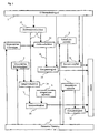
- Fig. 1A the closure system is shown, which in this case selectively opens and closes a urethra as body organ.
- the urethra has a closure element 1, which in this embodiment can be hydraulically actuated.
- a control system 3 To the closing element 1 is a control system 3, in this case hydraulically connected.
- the control system 3 serves to set a first state of the closure system, for example a closed state of the closure element 1.
- the control system 3 in the hydraulic embodiment, a first reservoir 5, via a pumping device 7 to build a certain pressure, so-called closing pressure on the closing element 1.
- the connecting line arriving at the closing element is divided into a first feed line Z1 and a second feed line Z2, the first feed line having the pumping device 7 and preferably a first shut-off valve V1 and the second feedline second Shut-off valve V2, wherein both the first supply line and the second supply line is connected to the first reservoir 5.
- the closure system according to the application can also be used merely as a device for selectively opening and closing a body organ, in this case the urethra.
- the pumping device 7, the first shut-off valve V1 and the second shut-off valve V2 are connected to a control unit 11, which takes over the conventional opening and closing of the closing element 1.
- the closure system according to the application further comprises a first sensor unit S1, which is preferably provided upstream of the closing element 1 of the tubular body member, a second sensor unit S2 which measures the pressure in the connecting line and a third sensor unit S3 on the pumping device 7. This makes a differential pressure measurement possible.
- the pump device 7 uses from the reservoir 5 as a food supply and generates a closing pressure on the closing element 1, which is selected such that the closing pressure seals the body organ via the closing element, but does not affect the blood supply to the body organ.
- the closing pressure corresponds to a pressure range that depends on different parameters, such. As body organ, vessel thickness, blood flow, etc. is dependent.
- the closing pressure In a short-term pressure increase in the body organ, for example in the urethra in the bladder by coughing, sneezing, laughing or other effort, the closing pressure is not sufficient and the flow in the body organ would take place briefly. For this case, it is advantageous if the closing pressure also increases briefly, so as to continue to maintain the tightness of the body organ.
- the short-term increase in the closing pressure caused by the closure system according to the application does not lead to necrosis formation, ie the circulation of the body organ is influenced only briefly and is thus not harmful to the body organ. In order to maintain this mechanism, it is necessary that the control system 3 has different pressure ranges. In the embodiment shown in FIG.
- the pump device 7 which is designed, for example, as a fast-switching pump or as a fast actuator, generates the required closing pressure via the first shut-off valve V1.
- the second shut-off valve V2 must be closed.
- the first shut-off valve V1 is closed, wherein the pump device 7 builds up to the first shut-off valve V1 increased compared to the closing pressure working pressure. If the flow through the body organ is carried out with the closing element, then only the second shut-off valve V 2 must be opened in order to reduce the closing pressure via the reservoir 5. But now occur upstream of the closing element 1 pressure peaks or short-term sustained pressure loads, so are the with the sensor device S1 registered or detected and passed on to the control unit 11.
- the control unit 11 opens the first shut-off valve V1 almost simultaneously, so that the increased working pressure acts on the closing element 1 and thus ensures, for a short time, that the body organ is also sealed against the pressure peaks.
- the control unit 11 closes the first shut-off valve again after a time constant and opens the second shut-off valve in order to reduce it to the required closing pressure from the increased working pressure.
- the pump device 7 can again build up an increased working pressure, which is applied to the first working valve V1, and thus prepare for a second process.
- the control system 3 is thus capable of a first state of the closure system, which is conventionally to be compared with the closing of the body organ via the closing element 1 via the selective opening, a deviation from the first state self-regulating to the first state due.
- This measure ensures that the closure system fulfills the task placed on the closure system in any situation, including in the case of strains such as coughing or sneezing. Since the closing pressure is adjusted by means of a fine-sensory control the pressure prevailing in the body organ upstream or bladder pressure in the bladder, necrosis phenomena are normally prevented be caused by a constant high closing pressure, whereby the blood circulation of the body organ is suppressed and thus causes long-term damage.
- the pump device 7 can also be replaced by a normal pump in conjunction with a second reservoir R2 and a third shut-off valve V3.
- the increased compared to the closing pressure working pressure is achieved in that the pump is applied to open the third shut-off valve, the reservoir R2 to the required working pressure, then the third shut-off valve V3 is then closed.
- the sensor elements are not only considered as pressure sensors, but also with capacitive or inductive sensors, the pressure can be determined, as well as volume changes can be measured via ultrasound or strain gauges, or a change in distance, which results in pressure increase, measured with light.
- the invention relates to a system for the electronic control of an artificial fine-sensory sphincter implant.
- the advanced system of an artificial sphincter implant extended by a fine sensor system and an actuator system is to be controlled in such a way that both complete continence can be ensured and at the same time the risk of necrosis caused by excessive and overly long pressure on the natural urethra minimized.
- the invention further provides a system for electronically controlling an artificial fine sensory sphincter implant.
- the electronic control which is the subject of this invention, converts signals of the fine sensor system, in particular the differential pressure between urinary bladder and cuff or a comparable differential pressure, into control commands to the actuators of the implant.
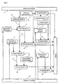
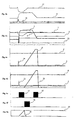
- the sensor signals applied to the signal inputs are amplified by means of amplifier circuits in such a way that, during operation, the signals move between the limit values predetermined by the circuit.
- the cuff pressure (4) moves in an area in which the circulation of the urethral tissue is guaranteed, but could easily lead to incontinence in increasing the intraocular pressure (11). If the differential pressure signal or the differential pressure value (1) rises, the cuff pressure (4) is lowered (16) when a bistable threshold value (3) is reached; if the differential pressure signal or the differential pressure value (1) falls below the lowered bistable threshold value (3), Lowering (16) of the cuff pressure (4) ended. This is done in the analog variant by means of a comparator function, which is provided with a hysteresis circuit.
- the actuators When dynamic loading occurs, the actuators must take on the function of a healthy sphincter, namely by active pressure transmission, thus avoiding the involuntary contraction of the sphincter under dynamic load incontinence.
- the cuff pressure (4) In case of sudden pressure increase, such as coughing or laughing, the cuff pressure (4) must be increased within milliseconds. As can be assumed at a differential pressure of zero incontinence, when falling below the differential pressure signal or the differential pressure value (1) below a threshold different from zero, the actuator to increase (15) of the cuff (4) causes.
- this lower threshold value which may fall below the differential pressure signal or the differential pressure value (1) only during micturition, to equip with an additive, active component.
- the differential pressure signal (1) is differentiated by means of a differentiator circuit and the output signal or the output value (14) of the differentiator function is raised by the lower threshold value by means of an adder circuit.
- the sensor signal is numerically differentiated by subtracting from the next to last signal value the current signal value and, if positive, adding the result to an offset component. The result serves as the lower threshold (12).
- the lower threshold value (12) in the event of a sudden increase in the internal bladder pressure (11) runs counter to the falling differential pressure signal or the differential pressure value (1) and thus enables an early activation of the actuators.
- Activation of the actuator system takes place in the analog variant by means of a comparator, which compares the differential pressure signal (1) with the lower threshold value (12).
- the comparator function is deactivated in unloaded operation to avoid an excessive cuff pressure (4) and the cuff pressure (4) is increased to a value, can be ensured in the continence, but the circulation of the affected Urethragewebes may be impaired.
- the achievement of this safety pressure is registered with a comparator or a comparator that compares the differential pressure signal or the differential pressure value (1) with a monostable threshold (2) and when the differential pressure signal is exceeded or of the differential pressure value (1) via this threshold value (2) triggers a signal which causes the actuators to terminate the increase (15) of the cuff pressure (4).
- This signal also activates the integrator element or the integrator function, which controls the depression (16) of the cuff pressure (4).
- the activation of the integrator element which controls the reduction (16) of the cuff pressure (4) in the analog variant, can take place in particular via the interruption of a discharge circuit of the capacitor counter-coupled to the operational amplifier of the integrator element.
- integration can take place and start value is equal to the voltage across the discharged capacitor.
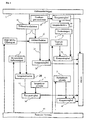
- the intelligent behavior of the electronic control is particularly evident in the fact that with continuous dynamic load, the reduction (16) of the cuff pressure (4) is delayed.
- an integrator element is used for this purpose.
- the cuff pressure (4) is quickly reduced again to levels that correspond to safe normal operation without risk of necrosis.
- the cuff pressure (4) is maintained at the high level until the dynamic load subsides.
- this is a signal analogous to the output signal (14) of the differentator element, in particular either the output signal (14) of the differentiator element itself or the output signal (12) of the adder element.
- a monostable reference signal (5) At the other input of the operational amplifier of the integrator member is a monostable reference signal (5).
- This monostable reference signal (5) is chosen such that it can be crossed by the voltage applied to the other input of the operational amplifier of the integrator element signal under dynamic load and thus volatile output signal (14) of the differentator.
- This wiring of the integrator member has the consequence that the output signal (13) of the integrator member away from the starting point when the input signal (14) of the differentiator analog input signal has not or rarely crossed the monostable reference signal (5), ie at low dynamics of the load .
- the input signal analogous to the output signal (14) of the differentiator element frequently crosses the monostable reference signal (5).
- the output signal (13) of the integrator element moves to the starting value. At high dynamics of the load thus the output signal (13) of the integrator member is driven zigzag against the starting value.
- the output signal (13) of the integrator element is compared by a comparator element with a constant threshold value (6) which may not be close to the starting value of the output signal (13) of the integrator element.
- the lowering (16) of the cuff pressure (4) is initiated. This reduction is made by the activation of the comparator, which causes the actuators to reduce (16) the cuff pressure (4) until the differential pressure signal (1) the lowered bistable Threshold signal (3) falls below.
- the cuff pressure (4) is now back in a safe area where the risk of necrosis is minimal. If a microprocessor is used, this numerically performs the same calculations in principle as the analog circuit and thus produces a comparable behavior.
- the artificial fine-sensory sphincter implant can be adapted to the individual requirements of the patient, on the one hand, the setting of parameters after completion of scarring after implantation, on the other hand with changing requirements by the patient, for example, with advancing age or the change in living habits.
- the monostable offset signal is the additive component which supplements the output signal (14) of the differentiator element to the lower switching threshold.
- the bistable threshold signal (3) can be varied if the cuff pressure (4) during normal operation already reaches critical values for the blood circulation of the urethral tissue, or if the bistable threshold signal (3) is set so low that the lowering (16) of the cuff pressure ( 4) is caused inappropriately frequently.
- the speed of integration can be adjusted.
- the monostable threshold signal (2) corresponds to the differential pressure signal or the differential pressure value (1), in which the cuff pressure (4) has a value at which ensures continence, but the circulation of the urethral tissue is impaired. If the monostable threshold signal (2) is too low, despite increased cuff pressure (4) at high dynamic load, the differential pressure signal or the differential pressure unit (1) can fall below the lower threshold and thus trigger a further Duckerhöhung. If the monostable threshold signal (2) is set too high, the urethral tissue can due to the high cuff pressure (4) damage or
- the admission pressure in the admission pressure vessel and thus the maximum cuff pressure (4) after pressure equalization is set.
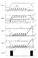
- the actuators controlled by the described analog circuit can use various methods and arrangements to produce the desired influence on the urethra.
- the different arrangements and components of the actuators require an adapted control electronics. Two hydraulic methods are described below by way of example, one with and one without pre-pressure container (29).
- valve (26) for lowering (16) of the cuff pressure (4) is opened, a pressure equalization takes place between the cuff (25) and the fluid reservoir (28).
- the valve (26) can be placed between the cuff (25) and the pump (27) as well as between the pump (27) and the fluid reservoir (28).
- a pre-pressure container (29) in this method allows a flash-like increase (15) of the cuff pressure (4).
- another pressure sensor is needed, which controls the regulation of the form (17).
- a pressure equalization is made possible by opening the valve (26) between the admission pressure vessel (29) and the cuff (25).
- the security pressure in the cuff (25) thus depends only on the previously set in the form-container (29) form (17).
- Decisive for the pressure equalization is also the construction of the pre-pressure container (29). The smaller the dimensions, the larger the form (17) must be.
- a signal is generated externally. This signal causes the actuator to decrease (16) of the cuff (4) and also disables the analog electronic circuit except for the comparator, which limits the Cuffnormaldruck up.
- a second external signal is generated, which again initiates the increase (15) of the cuff pressure (4).
- the cuff pressure (4) is increased until the differential pressure signal or the differential pressure value (1) reaches the bistable threshold value (3).
- a comparator reactivates the rest of the analog electronic circuitry.
- a novel fine-sensory implant which combines the most important aspects of technological problems of in-vivo medical technology in itself: a reliable fine sensors, intelligent, flexible control electronics with low power consumption, a miniaturized and powerful actuators and a mature energy and data transfer.
- a reliable fine sensors intelligent, flexible control electronics with low power consumption
- a miniaturized and powerful actuators and a mature energy and data transfer.
- an artificial, adaptive, fine-sensory sphincter the current technical state of implant technology should be discussed against the background of the developmental history and the methodological criteria for selection control and alternative design including intensive tests for the determination of individual components while considering comparable implants.
- An up-to-date system of an artificial bladder neck sphincter uses a hand pump in the scrotum or large labia to inflate the urinary flow cuff around the urethra [6].
- the problem with this system is the setting of Urethraver gleich horres.
- One too low Pressure leads to unwanted urine output under dynamic stress, which can be caused by laughter, coughing, sneezing or heavy lifting.
- Too much pressure on the urethra over a long period of time can easily lead to black tissue, a necrosis. In order to avoid this danger, so far in practice a slight stress incontinence with all its negative social consequences has been accepted.
- the artificial fine-sensory sphincter implant developed according to the invention replaces the hand pump with an active hydraulic system equipped with a fine sensor system and intelligent control. With this system, the active pressure transmission can be supported or replaced.
- the sensors primarily monitor the difference between internal bladder pressure and cuff pressure. Under dynamic load, the actuator is used to increase the cuff pressure, so continence is guaranteed even at these elevated pressure ratios. This may affect the normal circulation of the urethral tissue in the short term.
- the implant can distinguish between one-off and ongoing dynamic loading.
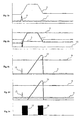
- urethral closure pressure (31) If urethral closure pressure (31) becomes negative, urine leakage occurs.
- the signal equivalent to the Urethraver gleichdruck (31) is determined from the two absolute pressure signals of the cuff (25) and the bladder ( Fig. 12a ). If there is a sudden dynamic load on the inside of the abdomen, this signal quickly approaches zero. In order to ensure a rapid reaction of the implant in this situation, the following measures are taken:
- the decrease in UrethraverBank horres (31) is bounded below by a switching threshold, which is above the incontinence range and can be varied during programming.
- This time-critical range is realized by means of analogous electronic components to allow a maximum reaction rate.
- the activation of the actuator is performed by a comparator, which compares the signal Urethraver gleich horres (31) with the lower threshold (12).
- the lowering of the increased cuff pressure under the normal pressure threshold (3) equipped with a hysteresis is microprocessor-controlled after the end of the dynamic load.
- the difference between an offset value (5), which can also be varied during programming, and the lower switching threshold (12) is integrated.
- the integration result (13) With continuous dynamic load, the integration result (13) is thus pressed downward in a zigzag manner. Without dynamic load, the integration result (13) increases up to a threshold value (6), upon reaching which the lowering of the cuff pressure is triggered (t 4 ) ( Fig. 12c ).
- the normal pressure threshold prevents excessive cuff pressure during normal operation. This function, like the activation of the actuators, is also realized with analogue electronic components.
- the analog circuit includes 4 variable parameters that are influenced by the D / A converter, namely: the rate of differentiation of the urethane closure pressure signal, the additive offset component of the lower threshold, and the mean and hysteresis of the normal pressure threshold.
- the permanently activated electronics is limited to a minimum of 6 operational amplifiers and a quad digital potentiometer of the analog circuit as well as the Signal conditioning and the RF receiver module.
- the total power consumption of the electronics amounts to less than 0.1 mW with the microprocessor in power-down mode.
- the programming of the artificial fine-sensory sphincter implant according to the invention is carried out by means of an external programming station. Via bi-directional transcutaneous data transfer, the urethral closure pressure and the absolute pressure in the pre-pressurized container are transferred to the programming station.
- the in-vivo pressure measurement paired with a simultaneous external urodynamic examination allows a far-reaching automation of implant programming.
- the patient performs defined physical movements, such as getting up from a sitting position or coughing. From the collected measurement data together with empirical values from clinical tests, the software can evaluate an optimal setting of the implant. Subsequent required adjustments to the programming, for example, to changed living conditions of the patient or to changed behavior of the implanted electronics are also possible manually.
- the absolute pressure in the cuff can also be measured by means of a differential pressure sensor, which measures the difference between the cuff pressure and the admission pressure.
- a differential pressure sensor measures the difference between the cuff pressure and the admission pressure.
- the absolute pressure signal of the cuff pressure can be filtered out from the absolute pressure signal of the admission pressure vessel and the differential pressure signal between the cuff and the admission pressure vessel. This allows the use of a cost-effective and reliable piezoresistive differential pressure sensor, which is connected via hydraulic connections both to the pre-pressure tank and to the cuff.
- an absolute pressure sensor similar to a cerebral pressure probe, is embedded in the tissue close to the bladder in order to avoid puncturing or opening the bladder [5].
- the measured pressure may not be exactly the same as the internal bladder pressure, but it is equivalent.
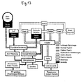
- the intended for the artificial fine-sensory sphincter implant control electronics is similar in terms of the requirements of a modern pacemaker.
- sensor signals are evaluated by a microprocessor and converted into actions of the implant.
- the microprocessor is operated in normal operation in power-down mode.
- the comparator which activates the actuators under dynamic load, simultaneously activates the microprocessor.
- microprocessor programmable via transcutaneous data transmission has the decisive advantage that it is possible to react flexibly to changes, for example, in the life habits of the patient or in the behavior of the electronic components.
- analog semiconductor components for example as an arithmetic circuit for determining the cuff absolute pressure, is thereby less critical.
- the analog components can be easily permanently activated.
- the only temporarily active microprocessor can be operated with relatively high clock frequencies, since the associated relatively high power consumption can be easily compensated by a significantly improved performance of the implant.
- a capacitor charged with up to 1kV must be switched (usually by IGBTs), which discharges via the human tissue between the electrodes with several ten amperes within a few milliseconds, the artifical fine sensory sphincter implant at a supply voltage of 4.2 V maximum continuous load currents of about 100 mA per switch connected.
- MOSFETs are available that can be operated directly by the microprocessor. To ensure reliability, several MOSFETs are connected in parallel per switching unit in order to handle the switching task without any problems if individual components fail. These can be integrated in a multi-chip module (MCM).
- MCM multi-chip module
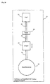
- Energy source is usually a lithium-ion battery, which is charged via a subcutaneously implanted induction coil.
- the charging controller of the lithium-ion battery pack is a commercial IC, which is used for example in mobile phones. It monitors the current flow between the energy transfer module and the battery, which it can influence with a MOSFET. Termination, abort and errors are reported to the microprocessor.
- the Aktorik of the artificial fine-sensory sphincter implant consists of electrically active components, the valves and the pump, and passive, a pre-pressure chamber, an inflatable cuff and the hydraulic connections ( FIG. 13 ). These components must be specially adapted for use in the artificial fine-sensory sphincter implant. Industrial pumps and valves are mostly designed for pressures of 10bar and more. Since maximum pressures of less than 500 mbar occur in the implant, an adapted dimensioning of these components makes sense.
- the pre-pressure container consists of a rigid base plate, via which an elastic membrane is tensioned. Due to the flat design of the pre-pressure container can be integrated into the outer shell of the implant so that the elastic membrane can bulge outward when pressure is increased.
- the crucial function of the artificial fine-sensory sphincter implant is the lightning-like increase in cuff pressure in the event of a sudden drop in urethral closure pressure.
- an increased pre-pressure is provided, which can be transmitted via the valve 3 to the cuff.
- the decisive gain in response time is to be expected when optimizing the system of admission pressure vessel, valve 3 and the hydraulic connection.
- Reaction times from activation of the actuators to the completion of the pressure equalization can be realized under 10 ms.
- a further enlargement of the inner radius even shorter reaction times can be realized.
- the inertia of the valve 3 causes a further delay, which increases with increasing opening radius r.
- This function can thus be integrated into the external charger.
- Micturition is controlled by unidirectional RF data transmission. This allows the patient comfortable and uncomplicated operation of the implant. The micturition request as well as a signal to stop the micturition will be transmitted.
Landscapes
- Health & Medical Sciences (AREA)
- Urology & Nephrology (AREA)
- Cardiology (AREA)
- Oral & Maxillofacial Surgery (AREA)
- Transplantation (AREA)
- Engineering & Computer Science (AREA)
- Biomedical Technology (AREA)
- Heart & Thoracic Surgery (AREA)
- Vascular Medicine (AREA)
- Life Sciences & Earth Sciences (AREA)
- Animal Behavior & Ethology (AREA)
- General Health & Medical Sciences (AREA)
- Public Health (AREA)
- Veterinary Medicine (AREA)
- Prostheses (AREA)
- Electrotherapy Devices (AREA)
- Selective Calling Equipment (AREA)
- Lock And Its Accessories (AREA)
- Power-Operated Mechanisms For Wings (AREA)
Priority Applications (1)
| Application Number | Priority Date | Filing Date | Title |
|---|---|---|---|
| EP20090000713 EP2123238A1 (de) | 2001-11-20 | 2002-11-19 | Verschlusssystem mit elektronische Steuerung |
Applications Claiming Priority (5)
| Application Number | Priority Date | Filing Date | Title |
|---|---|---|---|
| DE2001156558 DE10156558A1 (de) | 2001-11-20 | 2001-11-20 | Verschlusssystem und ein Verfahren hierzu |
| DE10156558 | 2001-11-20 | ||
| DE10239309 | 2002-08-27 | ||
| DE2002139309 DE10239309B4 (de) | 2002-08-27 | 2002-08-27 | Verfahren und System zur elektronischen Steuerung eines artifiziellen feinsensorischen Sphinkterimplantats |
| PCT/EP2002/012963 WO2003043534A2 (de) | 2001-11-20 | 2002-11-19 | Verschlusssystem und verfahren zur elektronischen steuerung |
Related Child Applications (1)
| Application Number | Title | Priority Date | Filing Date |
|---|---|---|---|
| EP20090000713 Division EP2123238A1 (de) | 2001-11-20 | 2002-11-19 | Verschlusssystem mit elektronische Steuerung |
Publications (2)
| Publication Number | Publication Date |
|---|---|
| EP1513466A2 EP1513466A2 (de) | 2005-03-16 |
| EP1513466B1 true EP1513466B1 (de) | 2009-01-21 |
Family
ID=26010600
Family Applications (2)
| Application Number | Title | Priority Date | Filing Date |
|---|---|---|---|
| EP02787734A Expired - Lifetime EP1513466B1 (de) | 2001-11-20 | 2002-11-19 | Verschlusssystem mit elektronischer steuerung |
| EP20090000713 Ceased EP2123238A1 (de) | 2001-11-20 | 2002-11-19 | Verschlusssystem mit elektronische Steuerung |
Family Applications After (1)
| Application Number | Title | Priority Date | Filing Date |
|---|---|---|---|
| EP20090000713 Ceased EP2123238A1 (de) | 2001-11-20 | 2002-11-19 | Verschlusssystem mit elektronische Steuerung |
Country Status (7)
| Country | Link |
|---|---|
| US (1) | US7217237B2 (da) |
| EP (2) | EP1513466B1 (da) |
| AT (1) | ATE421300T1 (da) |
| AU (1) | AU2002352060B2 (da) |
| DE (1) | DE50213247D1 (da) |
| DK (1) | DK1513466T3 (da) |
| WO (1) | WO2003043534A2 (da) |
Families Citing this family (28)
| Publication number | Priority date | Publication date | Assignee | Title |
|---|---|---|---|---|
| FR2878733B1 (fr) * | 2004-12-08 | 2007-03-30 | Francis Bartolome | Dispositif medical implante telecommande |
| US7775966B2 (en) | 2005-02-24 | 2010-08-17 | Ethicon Endo-Surgery, Inc. | Non-invasive pressure measurement in a fluid adjustable restrictive device |
| US8066629B2 (en) | 2005-02-24 | 2011-11-29 | Ethicon Endo-Surgery, Inc. | Apparatus for adjustment and sensing of gastric band pressure |
| US7699770B2 (en) | 2005-02-24 | 2010-04-20 | Ethicon Endo-Surgery, Inc. | Device for non-invasive measurement of fluid pressure in an adjustable restriction device |
| US8016744B2 (en) | 2005-02-24 | 2011-09-13 | Ethicon Endo-Surgery, Inc. | External pressure-based gastric band adjustment system and method |
| US7658196B2 (en) | 2005-02-24 | 2010-02-09 | Ethicon Endo-Surgery, Inc. | System and method for determining implanted device orientation |
| US7927270B2 (en) | 2005-02-24 | 2011-04-19 | Ethicon Endo-Surgery, Inc. | External mechanical pressure sensor for gastric band pressure measurements |
| US7775215B2 (en) | 2005-02-24 | 2010-08-17 | Ethicon Endo-Surgery, Inc. | System and method for determining implanted device positioning and obtaining pressure data |
| US8870742B2 (en) | 2006-04-06 | 2014-10-28 | Ethicon Endo-Surgery, Inc. | GUI for an implantable restriction device and a data logger |
| US8152710B2 (en) | 2006-04-06 | 2012-04-10 | Ethicon Endo-Surgery, Inc. | Physiological parameter analysis for an implantable restriction device and a data logger |
| US10702174B2 (en) | 2007-06-27 | 2020-07-07 | Integra Lifesciences Corporation | Medical monitor user interface |
| FR2920087B1 (fr) * | 2007-08-24 | 2009-10-23 | Univ Grenoble 1 | Dispositif de prevention de fuites urinaires |
| US20090171379A1 (en) * | 2007-12-27 | 2009-07-02 | Ethicon Endo-Surgery, Inc. | Fluid logic for regulating restriction devices |
| WO2009094431A2 (en) | 2008-01-23 | 2009-07-30 | Ams Research Corporation | Inflatable medical implant system |
| US8337389B2 (en) * | 2008-01-28 | 2012-12-25 | Ethicon Endo-Surgery, Inc. | Methods and devices for diagnosing performance of a gastric restriction system |
| US8696542B2 (en) | 2008-12-23 | 2014-04-15 | Ams Research Corporation | Biased artificial sphincter cuff |
| US8380312B2 (en) | 2009-12-31 | 2013-02-19 | Ams Research Corporation | Multi-zone stimulation implant system and method |
| US8449512B2 (en) | 2010-04-09 | 2013-05-28 | Davinci Biomedical Research Products Inc. | Stoma stabilitating device and method |
| US9731112B2 (en) | 2011-09-08 | 2017-08-15 | Paul J. Gindele | Implantable electrode assembly |
| DE102012215243B4 (de) | 2012-08-28 | 2016-06-30 | Dualis Medtech Gmbh | Künstlicher Sphinkter |
| FR3001631B1 (fr) * | 2013-02-01 | 2015-02-06 | Uromems | Systeme de controle d'un sphincter artificiel implantable dans le corps humain ou animal |
| US9636070B2 (en) | 2013-03-14 | 2017-05-02 | DePuy Synthes Products, Inc. | Methods, systems, and devices for monitoring and displaying medical parameters for a patient |
| FR3028749B1 (fr) * | 2014-11-25 | 2020-10-09 | Uromems | Systeme occlusif implantable |
| TWI670046B (zh) * | 2016-03-29 | 2019-09-01 | 豪展醫療科技股份有限公司 | 兼具情緒壓力指數檢測與血壓檢測之量測裝置與方法 |
| AT518714B1 (de) * | 2016-06-03 | 2018-09-15 | Ami Agency Medical Innovations Gmbh | Medizinische Einrichtung zum Verengen oder Absperren eines Körperkanals |
| AT518411B1 (de) * | 2016-06-14 | 2017-10-15 | Ami Agency Medical Innovations Gmbh | Medizinische Einrichtung zum Absperren eines Körperkanals |
| AT518764B1 (de) | 2016-06-14 | 2018-03-15 | Ami Agency Medical Innovations Gmbh | Medizinische Einrichtung zum Absperren eines Körperkanals |
| US11903806B2 (en) | 2018-03-02 | 2024-02-20 | United States Government As Represented By The Department Of Veterans Affairs | Devices and systems for treatment of urinary incontinence, and methods of making and using same |
Family Cites Families (18)
| Publication number | Priority date | Publication date | Assignee | Title |
|---|---|---|---|---|
| US4417567A (en) * | 1981-08-12 | 1983-11-29 | Medical Engineering Corporation | Artificial sphincter |
| US4571749A (en) | 1982-09-21 | 1986-02-25 | The Johns Hopkins University | Manually actuated hydraulic sphincter |
| US4682583A (en) * | 1984-04-13 | 1987-07-28 | Burton John H | Inflatable artificial sphincter |
| GB8512069D0 (en) * | 1985-05-13 | 1985-06-19 | Craggs M D | Prosthetic sphincter devices |
| DE3539498A1 (de) | 1985-11-07 | 1987-05-21 | Weiser Hans Fred Dr | Implantierbare prothese zum verschluss eines koerperausganges |
| US4994020A (en) | 1989-07-21 | 1991-02-19 | American Medical Systems, Inc. | Implantable artificial sphincter system |
| FR2653993B1 (fr) | 1989-11-03 | 1992-01-10 | Synthelabo | Inverseur hydraulique de pression destine a la commande d'un sphincter artificiel, et prothese implantable comportant ledit inverseur. |
| DE4140055C2 (de) | 1990-11-30 | 1995-08-03 | Steindorf Susanne Ruth | Vorrichtung zur Funktionsdiagnose des Kontinenzorgans |
| DE4331658B4 (de) | 1993-09-17 | 2009-12-10 | Eska Medical Gmbh & Co | Implantierbare Vorrichtung zum wahlweisen Öffnen und Verschließen von rohrförmigen Körperorganen, insbesondere der Harnröhre |
| WO1998031301A1 (en) | 1997-01-15 | 1998-07-23 | Lenadora Shantha Jayatilake Ba | Device for genuine stress incontinence in the female |
| US6135945A (en) * | 1997-08-04 | 2000-10-24 | Sultan; Hashem | Anti-incontinence device |
| DE19845292A1 (de) | 1997-09-05 | 1999-05-20 | Michael Dr Waldner | Implantierbarer, extrakorporal steuerbarer Kompressionsverschluß zur Regelung der Blasen und Darmentleerung |
| US6095969A (en) * | 1998-03-03 | 2000-08-01 | Karram; Mickey M. | Female incontinence control device actuated by abdominal pressure |
| US6074341A (en) | 1998-06-09 | 2000-06-13 | Timm Medical Technologies, Inc. | Vessel occlusive apparatus and method |
| AU5909399A (en) * | 1998-09-15 | 2000-04-03 | Infinite Biomedical Technologies, Incorporated | Intraurethral continent prothesis |
| MXPA02007651A (es) * | 2000-02-10 | 2004-08-23 | Potencia Medical Ag | Aparato de tratamiento de incontinencia anal con suministro inalambrico de energia. |
| AU2001232583A1 (en) | 2000-02-14 | 2001-07-24 | Potencia Medical Ag | Hydraulic urinary incontinence treatment apparatus |
| DE10013519A1 (de) | 2000-03-20 | 2001-10-04 | Adeva Medical Ges Fuer Entwick | Implantierbare Sphinkterprothese |
-
2002
- 2002-11-19 EP EP02787734A patent/EP1513466B1/de not_active Expired - Lifetime
- 2002-11-19 AT AT02787734T patent/ATE421300T1/de active
- 2002-11-19 DE DE50213247T patent/DE50213247D1/de not_active Expired - Lifetime
- 2002-11-19 AU AU2002352060A patent/AU2002352060B2/en not_active Ceased
- 2002-11-19 US US10/496,423 patent/US7217237B2/en not_active Expired - Fee Related
- 2002-11-19 WO PCT/EP2002/012963 patent/WO2003043534A2/de not_active Ceased
- 2002-11-19 EP EP20090000713 patent/EP2123238A1/de not_active Ceased
- 2002-11-19 DK DK02787734T patent/DK1513466T3/da active
Also Published As
| Publication number | Publication date |
|---|---|
| ATE421300T1 (de) | 2009-02-15 |
| US7217237B2 (en) | 2007-05-15 |
| DK1513466T3 (da) | 2009-05-25 |
| AU2002352060A1 (en) | 2003-06-10 |
| US20050240144A1 (en) | 2005-10-27 |
| EP1513466A2 (de) | 2005-03-16 |
| AU2002352060B2 (en) | 2009-08-27 |
| WO2003043534A2 (de) | 2003-05-30 |
| WO2003043534A3 (de) | 2004-03-04 |
| DE50213247D1 (da) | 2009-03-12 |
| EP2123238A1 (de) | 2009-11-25 |
Similar Documents
| Publication | Publication Date | Title |
|---|---|---|
| EP1513466B1 (de) | Verschlusssystem mit elektronischer steuerung | |
| DE4438201C2 (de) | Gerät zur langzeitigen Normalisierung des Kammerwasserabflusses aus dem menschlichen Auge | |
| DE69008954T2 (de) | Einsetzbares künstliches Schliessmuskelsystem. | |
| EP3463182B1 (de) | Medizinische einrichtung zum verengen oder absperren eines körperkanals | |
| DE69935727T2 (de) | Vorrichtung zur behandlung von inkontinenz | |
| DE60316035T2 (de) | Vorrichtung zur schonenden inkontinenzbehandlung | |
| US4571749A (en) | Manually actuated hydraulic sphincter | |
| EP0810001B1 (de) | Vorrichtung zur Behandlung von Harnblasen-Entleerungsstörungen des Mannes und der Frau | |
| US4731083A (en) | Manually actuated hydraulic sphincter | |
| DE69730977T2 (de) | Auf den Druck ansprechendes Blockierventil und Verfahren zu seiner Verwendung | |
| DE69002920T2 (de) | Steuereinrichtung für einen künstlichen Schliessmuskel und implantierbare Prothese mit dieser Vorrichtung. | |
| DE10155087A1 (de) | Implantierbares Muskelstimulationsgerät | |
| EP1265551B1 (de) | Implantierbare sphinkterprothese | |
| WO2018130358A1 (de) | Künstlicher schliessmuskel | |
| DE10239309B4 (de) | Verfahren und System zur elektronischen Steuerung eines artifiziellen feinsensorischen Sphinkterimplantats | |
| DE3127882A1 (de) | Mess- und ableitungsvorrichtung zum studium sowie zur behandlung des hydrocephalus und zum monitoring bei externer liquordrainage | |
| DE19654990A1 (de) | Implantat zur kontrollierten Ableitung von Gehirnflüssigkeit | |
| DE102012215243B4 (de) | Künstlicher Sphinkter | |
| DE10046027B4 (de) | Künstliches Harnableitungssystem | |
| EP4215158B1 (de) | Künstlicher schliessmuskel | |
| DE19915558C2 (de) | Regelndes Implantat zur Normalisierung des Liquordruckes | |
| EP2265213B1 (de) | Implantierbarer reservoirkörper | |
| DE10156558A1 (de) | Verschlusssystem und ein Verfahren hierzu | |
| DE102005002791A1 (de) | Vorrichtung und Verfahren zur Einstellung von intraokularem Druck | |
| DE202008018261U1 (de) | Implantierbarer Reservoirkörper |
Legal Events
| Date | Code | Title | Description |
|---|---|---|---|
| PUAI | Public reference made under article 153(3) epc to a published international application that has entered the european phase |
Free format text: ORIGINAL CODE: 0009012 |
|
| 17P | Request for examination filed |
Effective date: 20040618 |
|
| AK | Designated contracting states |
Kind code of ref document: A2 Designated state(s): AT BE BG CH CY CZ DE DK EE ES FI FR GB GR IE IT LI LU MC NL PT SE SK TR |
|
| AX | Request for extension of the european patent |
Extension state: AL LT LV MK RO SI |
|
| RAP1 | Party data changed (applicant data changed or rights of an application transferred) |
Owner name: WASSERMANN, HELMUT Owner name: JOCHAM, DIETER |
|
| RIN1 | Information on inventor provided before grant (corrected) |
Inventor name: WASSERMANN, HELMUT Inventor name: HO, CHI-NGHIA Inventor name: SCHOSTEK, SEBASTIAN |
|
| 17Q | First examination report despatched |
Effective date: 20060515 |
|
| GRAP | Despatch of communication of intention to grant a patent |
Free format text: ORIGINAL CODE: EPIDOSNIGR1 |
|
| RTI1 | Title (correction) |
Free format text: CLOSING SYSTEM WITH ELECTRONIC CONTROL |
|
| DAX | Request for extension of the european patent (deleted) | ||
| GRAS | Grant fee paid |
Free format text: ORIGINAL CODE: EPIDOSNIGR3 |
|
| GRAA | (expected) grant |
Free format text: ORIGINAL CODE: 0009210 |
|
| AK | Designated contracting states |
Kind code of ref document: B1 Designated state(s): AT BE BG CH CY CZ DE DK EE ES FI FR GB GR IE IT LI LU MC NL PT SE SK TR |
|
| REG | Reference to a national code |
Ref country code: GB Ref legal event code: FG4D Free format text: NOT ENGLISH |
|
| REG | Reference to a national code |
Ref country code: CH Ref legal event code: EP |
|
| REG | Reference to a national code |
Ref country code: IE Ref legal event code: FG4D Free format text: LANGUAGE OF EP DOCUMENT: GERMAN |
|
| REF | Corresponds to: |
Ref document number: 50213247 Country of ref document: DE Date of ref document: 20090312 Kind code of ref document: P |
|
| REG | Reference to a national code |
Ref country code: DK Ref legal event code: T3 |
|
| REG | Reference to a national code |
Ref country code: CH Ref legal event code: NV Representative=s name: ISLER & PEDRAZZINI AG |
|
| PG25 | Lapsed in a contracting state [announced via postgrant information from national office to epo] |
Ref country code: FI Free format text: LAPSE BECAUSE OF FAILURE TO SUBMIT A TRANSLATION OF THE DESCRIPTION OR TO PAY THE FEE WITHIN THE PRESCRIBED TIME-LIMIT Effective date: 20090121 Ref country code: ES Free format text: LAPSE BECAUSE OF FAILURE TO SUBMIT A TRANSLATION OF THE DESCRIPTION OR TO PAY THE FEE WITHIN THE PRESCRIBED TIME-LIMIT Effective date: 20090502 |
|
| REG | Reference to a national code |
Ref country code: IE Ref legal event code: FD4D |
|
| PG25 | Lapsed in a contracting state [announced via postgrant information from national office to epo] |
Ref country code: PT Free format text: LAPSE BECAUSE OF FAILURE TO SUBMIT A TRANSLATION OF THE DESCRIPTION OR TO PAY THE FEE WITHIN THE PRESCRIBED TIME-LIMIT Effective date: 20090622 Ref country code: SE Free format text: LAPSE BECAUSE OF FAILURE TO SUBMIT A TRANSLATION OF THE DESCRIPTION OR TO PAY THE FEE WITHIN THE PRESCRIBED TIME-LIMIT Effective date: 20090421 |
|
| PG25 | Lapsed in a contracting state [announced via postgrant information from national office to epo] |
Ref country code: IE Free format text: LAPSE BECAUSE OF FAILURE TO SUBMIT A TRANSLATION OF THE DESCRIPTION OR TO PAY THE FEE WITHIN THE PRESCRIBED TIME-LIMIT Effective date: 20090121 Ref country code: CZ Free format text: LAPSE BECAUSE OF FAILURE TO SUBMIT A TRANSLATION OF THE DESCRIPTION OR TO PAY THE FEE WITHIN THE PRESCRIBED TIME-LIMIT Effective date: 20090121 Ref country code: EE Free format text: LAPSE BECAUSE OF FAILURE TO SUBMIT A TRANSLATION OF THE DESCRIPTION OR TO PAY THE FEE WITHIN THE PRESCRIBED TIME-LIMIT Effective date: 20090121 |
|
| PLBE | No opposition filed within time limit |
Free format text: ORIGINAL CODE: 0009261 |
|
| STAA | Information on the status of an ep patent application or granted ep patent |
Free format text: STATUS: NO OPPOSITION FILED WITHIN TIME LIMIT |
|
| PG25 | Lapsed in a contracting state [announced via postgrant information from national office to epo] |
Ref country code: SK Free format text: LAPSE BECAUSE OF FAILURE TO SUBMIT A TRANSLATION OF THE DESCRIPTION OR TO PAY THE FEE WITHIN THE PRESCRIBED TIME-LIMIT Effective date: 20090121 |
|
| 26N | No opposition filed |
Effective date: 20091022 |
|
| PG25 | Lapsed in a contracting state [announced via postgrant information from national office to epo] |
Ref country code: BG Free format text: LAPSE BECAUSE OF FAILURE TO SUBMIT A TRANSLATION OF THE DESCRIPTION OR TO PAY THE FEE WITHIN THE PRESCRIBED TIME-LIMIT Effective date: 20090421 |
|
| BERE | Be: lapsed |
Owner name: WASSERMANN, HELMUT Effective date: 20091130 Owner name: JOCHAM, DIETER Effective date: 20091130 |
|
| PG25 | Lapsed in a contracting state [announced via postgrant information from national office to epo] |
Ref country code: MC Free format text: LAPSE BECAUSE OF NON-PAYMENT OF DUE FEES Effective date: 20091130 |
|
| PG25 | Lapsed in a contracting state [announced via postgrant information from national office to epo] |
Ref country code: GR Free format text: LAPSE BECAUSE OF FAILURE TO SUBMIT A TRANSLATION OF THE DESCRIPTION OR TO PAY THE FEE WITHIN THE PRESCRIBED TIME-LIMIT Effective date: 20090422 Ref country code: BE Free format text: LAPSE BECAUSE OF NON-PAYMENT OF DUE FEES Effective date: 20091130 |
|
| PG25 | Lapsed in a contracting state [announced via postgrant information from national office to epo] |
Ref country code: IT Free format text: LAPSE BECAUSE OF FAILURE TO SUBMIT A TRANSLATION OF THE DESCRIPTION OR TO PAY THE FEE WITHIN THE PRESCRIBED TIME-LIMIT Effective date: 20090121 |
|
| PG25 | Lapsed in a contracting state [announced via postgrant information from national office to epo] |
Ref country code: LU Free format text: LAPSE BECAUSE OF NON-PAYMENT OF DUE FEES Effective date: 20091119 |
|
| PG25 | Lapsed in a contracting state [announced via postgrant information from national office to epo] |
Ref country code: TR Free format text: LAPSE BECAUSE OF FAILURE TO SUBMIT A TRANSLATION OF THE DESCRIPTION OR TO PAY THE FEE WITHIN THE PRESCRIBED TIME-LIMIT Effective date: 20090121 |
|
| PG25 | Lapsed in a contracting state [announced via postgrant information from national office to epo] |
Ref country code: CY Free format text: LAPSE BECAUSE OF FAILURE TO SUBMIT A TRANSLATION OF THE DESCRIPTION OR TO PAY THE FEE WITHIN THE PRESCRIBED TIME-LIMIT Effective date: 20090121 |
|
| PGFP | Annual fee paid to national office [announced via postgrant information from national office to epo] |
Ref country code: DK Payment date: 20121120 Year of fee payment: 11 |
|
| PGFP | Annual fee paid to national office [announced via postgrant information from national office to epo] |
Ref country code: FR Payment date: 20121130 Year of fee payment: 11 Ref country code: CH Payment date: 20121122 Year of fee payment: 11 |
|
| PGFP | Annual fee paid to national office [announced via postgrant information from national office to epo] |
Ref country code: GB Payment date: 20121120 Year of fee payment: 11 |
|
| PGFP | Annual fee paid to national office [announced via postgrant information from national office to epo] |
Ref country code: NL Payment date: 20121120 Year of fee payment: 11 Ref country code: AT Payment date: 20121113 Year of fee payment: 11 |
|
| REG | Reference to a national code |
Ref country code: NL Ref legal event code: V1 Effective date: 20140601 |
|
| REG | Reference to a national code |
Ref country code: DK Ref legal event code: EBP Effective date: 20131130 |
|
| REG | Reference to a national code |
Ref country code: CH Ref legal event code: PL |
|
| REG | Reference to a national code |
Ref country code: AT Ref legal event code: MM01 Ref document number: 421300 Country of ref document: AT Kind code of ref document: T Effective date: 20131119 |
|
| GBPC | Gb: european patent ceased through non-payment of renewal fee |
Effective date: 20131119 |
|
| PG25 | Lapsed in a contracting state [announced via postgrant information from national office to epo] |
Ref country code: CH Free format text: LAPSE BECAUSE OF NON-PAYMENT OF DUE FEES Effective date: 20131130 Ref country code: LI Free format text: LAPSE BECAUSE OF NON-PAYMENT OF DUE FEES Effective date: 20131130 |
|
| REG | Reference to a national code |
Ref country code: FR Ref legal event code: ST Effective date: 20140731 |
|
| PG25 | Lapsed in a contracting state [announced via postgrant information from national office to epo] |
Ref country code: NL Free format text: LAPSE BECAUSE OF NON-PAYMENT OF DUE FEES Effective date: 20140601 Ref country code: AT Free format text: LAPSE BECAUSE OF NON-PAYMENT OF DUE FEES Effective date: 20131119 |
|
| PG25 | Lapsed in a contracting state [announced via postgrant information from national office to epo] |
Ref country code: DK Free format text: LAPSE BECAUSE OF NON-PAYMENT OF DUE FEES Effective date: 20131130 |
|
| PG25 | Lapsed in a contracting state [announced via postgrant information from national office to epo] |
Ref country code: FR Free format text: LAPSE BECAUSE OF NON-PAYMENT OF DUE FEES Effective date: 20131202 Ref country code: GB Free format text: LAPSE BECAUSE OF NON-PAYMENT OF DUE FEES Effective date: 20131119 |
|
| PGFP | Annual fee paid to national office [announced via postgrant information from national office to epo] |
Ref country code: DE Payment date: 20151230 Year of fee payment: 14 |
|
| REG | Reference to a national code |
Ref country code: DE Ref legal event code: R119 Ref document number: 50213247 Country of ref document: DE |
|
| PG25 | Lapsed in a contracting state [announced via postgrant information from national office to epo] |
Ref country code: DE Free format text: LAPSE BECAUSE OF NON-PAYMENT OF DUE FEES Effective date: 20170601 |