EP1513262B1 - Communication method, communication system, and communication device - Google Patents
Communication method, communication system, and communication device Download PDFInfo
- Publication number
- EP1513262B1 EP1513262B1 EP03733294A EP03733294A EP1513262B1 EP 1513262 B1 EP1513262 B1 EP 1513262B1 EP 03733294 A EP03733294 A EP 03733294A EP 03733294 A EP03733294 A EP 03733294A EP 1513262 B1 EP1513262 B1 EP 1513262B1
- Authority
- EP
- European Patent Office
- Prior art keywords
- communication
- inquiry message
- processing
- communication device
- terminal device
- Prior art date
- Legal status (The legal status is an assumption and is not a legal conclusion. Google has not performed a legal analysis and makes no representation as to the accuracy of the status listed.)
- Expired - Lifetime
Links
Images


Classifications
-
- H—ELECTRICITY
- H04—ELECTRIC COMMUNICATION TECHNIQUE
- H04W—WIRELESS COMMUNICATION NETWORKS
- H04W48/00—Access restriction; Network selection; Access point selection
- H04W48/16—Discovering, processing access restriction or access information
-
- H—ELECTRICITY
- H04—ELECTRIC COMMUNICATION TECHNIQUE
- H04W—WIRELESS COMMUNICATION NETWORKS
- H04W4/00—Services specially adapted for wireless communication networks; Facilities therefor
- H04W4/80—Services using short range communication, e.g. near-field communication [NFC], radio-frequency identification [RFID] or low energy communication
-
- H—ELECTRICITY
- H04—ELECTRIC COMMUNICATION TECHNIQUE
- H04W—WIRELESS COMMUNICATION NETWORKS
- H04W76/00—Connection management
- H04W76/10—Connection setup
-
- H—ELECTRICITY
- H04—ELECTRIC COMMUNICATION TECHNIQUE
- H04W—WIRELESS COMMUNICATION NETWORKS
- H04W84/00—Network topologies
- H04W84/18—Self-organising networks, e.g. ad-hoc networks or sensor networks
Definitions
- the present invention relates to a communication method suitable to be applied to a communication method of performing comparatively close range wireless communication and to a communication system in which the communication method is performed as well as a communication device which is applicable to the communication system.
- Bluetooth® communication has attracted an attention as a close range wireless communication method up to approximately 100m at maximum and various kinds of supporting device have been developed.
- a close range wireless communication system such as the Bluetooth® communication which uses a wireless signal of a comparatively high frequency wave has an advantage such as no directivity and high transmissivity in comparison to an infrared data communication method which uses an infrared signal, and is expected that devices supporting the system increase in the future.
- an inquiry message is transmitted as a broadcast message from a device which intends to start communication (hereinafter, referred to as a device A) in order to discover devices which exist in the neighborhood thereof. Then, a device which has received the inquiry message from the device A sends back a response message to the device A in response to that inquiry message.
- the device A can discover a plurality of communicable devices which exist in the neighborhood.
- the device A selects and specifies a device to which the connection is tried, and connection processing with respect to the device is performed.
- the response messages are received from a plurality of devices, conventionally those are displayed in a form of list so that a user can make a selection.
- a profile there are a serial port profile to perform serial communication, a personal area networking profile to realize a personal area network and the like.
- a service discovery protocol (hereinafter, referred to as a SDP) is defined as a procedure to determine those profiles and a service which is actually implemented.
- the device A transmits to a device to be connected (hereinafter, referred to as a device B) an inquiry message querying what kind of service is provided by the device B in accordance with the SDP, the device B receives the inquiry message from the device A and then transmits to the device A information regarding a service provided by the device B as a response message to the inquiry. If the device B provides a desired service, the device A having received the response message requests the communication for the service, so that the desired service can be started between the device A and the device B.
- a device B a device to be connected
- an inquiry message querying what kind of service is provided by the device B in accordance with the SDP
- the device B receives the inquiry message from the device A and then transmits to the device A information regarding a service provided by the device B as a response message to the inquiry. If the device B provides a desired service, the device A having received the response message requests the communication for the service, so that the desired service can be started between the device A and the device B.
- a basic communication procedure in the Bluetooth® communication is that first the device A performs transmission of an inquiry message in order to discover a device which exists in the neighborhood and also performs reception of a response message thereto; selects a desired device from devices which have responded; further, makes an inquiry to the device whether the desired service is available; and furthermore, requests the communication for that service.
- Bluetooth® standard is managed by Bluetooth SIG Inc. and specifications describing the details are published by Bluetooth SIG Inc..
- Bluetooth Spec VII is detailed in " part A, A Radio Specification (15-32), B Baseand specification - channel control (92-110), C. Link Manager Protocol - Power control (222-223)" 8 May 2001, XP002282703 .
- an inquiry message to discover a device which exists in the neighborhood is targeted at all devices which exist within a communicable range (for example, from 10m to 100m). Accordingly, when many communicable devices exist in the neighborhood, enormous number of response messages are to be received. Conventionally, such an operation procedure of showing information regarding a device included in those response messages in a display or the like is required so that a user can select the desired device; however, when many devices exist in the neighborhood, the user must spend a huge amount of time for the selection operation and its usability becomes deteriorated, which has been a problem. Further, in order to judge whether the device is really a target device to connect or not, information such as an ID which is provided by the device needs to be identified, and therefore, there has been a possibility for the user to make an excessive operation.
- the present invention is made in view of such circumstances, and aims to perform easily and securely a communication service between devices when performing wireless communication which is represented by the Bluetooth® communication.
- WO-A-01168660 discloses a communication device, wherein the communicating signal is increased following connection.
- a first aspect of the present invention provides a communication method in which at least first and second communication devices are provided and wireless communication is performed between the respective communication devices in accordance with a predetermined communication method, wherein when a predetermined connection operation is performed in said first communication device, an inquiry message to discover a device to be connected by the wireless communication is wirelessly transmitted after restricting a transmissible distance to a close range the processing to restrict said transmissible distance to the close range is processing to set transmission power to a limited value compared to the transmission power at the time of normal wireless communication; when a predetermined standby operation is performed in said second communication device, said inquiry message is received and a response message to the received inquiry message is wirelessly transmitted; and said first communication device performs connection processing with respect to said second communication device, when the response message is received; wherein wireless transmission of the inquiry message by a predetermined connection operation and/or reception of the inquiry message by a predetermined standby operation is performed while operation means provided in the respective communication devices are continuously operated; and said second communication device lowers reception sensitivity to the inquiry message, so
- a target device can be specified by bringing devices to be connected close to each other and by depressing buttons for connection on both sides or the like, the communication between the specific devices can be established easily and securely, and the transmissible distance can be restricted to a close range due to the limitation of the transmission power and only the inquiry message wirelessly transmitted from the close range can easily be received.
- An aspect of the present invention is the communication method according to the first aspect of the present invention, wherein the wireless transmission of the inquiry message by the predetermined connection operation and/or the reception of the inquiry message by the predetermined standby operation are performed while operation means provided in respective communication devices are continuously operated. Accordingly, the transmission or the reception of the inquiry message can be performed excellently in the continuous operation.
- An aspect of the present invention is the communication method according to the first aspect of the present invention, wherein after the connection processing is completed, data transfer processing is performed in accordance with a program which is being executed in the first communication device or in the second communication device. Accordingly, the data transfer processing can be performed at excellent timing.
- An aspect of the present invention is the communication method according to the first aspect of the present invention, wherein the connection operation in the first communication device and the standby operation in the second communication device are made to be a common operation, and when the common operation is performed, transmission processing of the inquiry message and reception processing of the inquiry message are made to be performed alternately. Accordingly, both the transmission processing of the inquiry message and the reception processing of the inquiry message can be performed in a single operation.
- An aspect of the present invention is the communication method according to the first aspect of the present invention, wherein the connection operation in the first communication device is a limited inquiry message which is distinguishable from a type of the inquiry message and the second communication device is made to await the limited inquiry message. Accordingly, transmission processing of the limited inquiry message can be performed.
- An aspect of the present invention is the communication method according to the first aspect of the present invention, wherein the connection operation in the first communication device is made to select a general inquiry message or an arbitrary limited inquiry message which should be transmitted, and the second communication device is made to select the general inquiry message or the arbitrary limited inquiry message which should be awaited. Accordingly, both the transmission of the general inquiry message and the transmission of the limited inquiry message can be performed.
- a second aspect of the present invention provides a communication system in which at least first and second communication devices are provided and wireless communication is performed between respective communication devices by a predetermined communication method
- said first communication device comprises: communication processing means to perform transmission and reception of a wireless signal connection operation means, and control means to make an inquiry message transmitted from said communication processing means in a state in which a transmissible distance is restricted to a close range when said connection operation means is operated and to perform connection processing with respect to a transmission source of the response message when the response message to the inquiry message is received;
- the processing to restrict the transmissible distance to the close range in said first communication device is processing to set transmission power in said communication processing means to a limited value compared to the transmission power at the time of normal wireless communication
- said second communication device comprises: communication processing means to perform transmission and reception of a wireless signal, standby operation means, and control means to make said inquiry message received by said communication processing means when said standby operation means is operated and to make the response message to the received inquiry message wirelessly transmitted by said communication processing means; wherein while the connection
- a target device can be specified by bringing devices to be connected close to each other and by depressing buttons for connection on both sides or the like, the communication between the specific devices can be established easily and securely, and the transmissible distance can be restricted to the close range due to the limitation of the transmission power , and only the inquiry message which is transmitted wirelessly from the close range can easily be received
- An aspect of the present invention is the communication system according to the second aspect of the present invention, wherein while the connection operation means of the first communication device is continuously operated, the control means of the first communication device makes the inquiry message transmitted; and while the standby operation means of the second communication device is continuously operated, the control means of the second communication device makes the inquiry message received. Accordingly, the transmission or the reception of the inquiry message can be performed excellently in the continuous operation.
- An aspect of the present invention is the communication system according to the second aspect of the present invention, wherein when the connection processing by the control means of the first communication device is completed, data transfer processing is performed in accordance with a program which is being executed in the first or the second communication device. Accordingly, the data transfer processing can be performed at excellent timing.
- An aspect of the present invention is the communication system according to the second aspect of the present invention, wherein the connection operation means of the first communication device and the standby operation means of the second communication device are made to be a common operation means, and when the common operation means is operated, the control means of respective communication devices perform control to make the transmission processing of the inquiry message and the reception processing of the inquiry message alternately performed by the communication processing means. Accordingly, both the transmission processing of the inquiry message and the reception processing of the inquiry message can be performed in a single operation
- An aspect of the present invention is the communication system according to the second aspect of the present invention, wherein the inquiry message in the first communication device is a limited inquiry message which is distinguishable from a general inquiry message, and the second communication device is made to await the limited inquiry message. Accordingly, transmission processing of the limited inquiry message can be performed.
- An aspect of the present invention is the communication system according to the second aspect of the present invention, wherein the connection operation in the first communication device is made to select a general inquiry message or an arbitrary limited inquiry message which should be transmitted and the second communication device is made to select the general inquiry message or the arbitrary limited inquiry message which should be awaited. Accordingly, both the transmission of the general inquiry message and the transmission of the limited inquiry message can be performed.
- a third aspect of the present invention provides a communication device which performs wireless communication with another communication device using a predetermined communication method, including: a communication processing means to perform transmission and reception of a wireless signal, a standby operation means, and a control means to make an inquiry message received by the communication processing means when the standby operation means is operated and to make a response message to the received inquiry message wirelessly transmitted by the communication processing means. Accordingly, the communication with a specific device can be established easily and securely, and the reception of the inquiry message can be performed excellently in the continuous operation.
- An aspect of the present invention is the communication device according to the third aspect of the present invention, wherein the communication processing means makes the reception sensitivity to the inquiry message lower so that only the inquiry message wirelessly transmitted from the close range can be received. Accordingly, only the inquiry message transmitted from the close range can be received easily.
- An aspect of the present invention is the communication device according to the third aspect of the present invention, wherein the standby operation means includes a means to select the inquiry message which should be awaited so that the inquiry message of a selected arbitrary type can be received. Accordingly, the inquiry message of the selected type can be received.
- the present invention is applied to a handheld information terminal device to perform wireless communication according to the Bluetooth® communication which is one of wireless communication methods used in comparatively close range wireless communication.
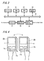
- FIG. 1 is a view showing an example of an external appearance of a handheld information terminal device according to this embodiment.
- a handheld information terminal device 10 of this embodiment is provided with a display panel 11 including a liquid crystal picture display means or the like in which characters and figures can be displayed on the display panel 11.
- the display panel 11 is included as a touch panel, so that input operation can be performed by touching with a finger or an input stylus.
- a connection button 17a and a standby button 17b are arranged as operation buttons. Other operation buttons may be arranged as well.
- the handheld information terminal device 10 is a device capable of performing the wireless communication according to the Bluetooth® communication which is one of wireless communication methods, and is configured to be capable of performing transmission data to and reception data from another device by the Bluetooth® wireless communication.
- the connection button 17a is a button to start connection of the wireless communication to another device which exists in the neighborhood of the handheld information terminal device 10
- the standby button 17b is a button to set a receivable state in accordance with a connection request for wireless communication to the handheld information terminal device 10 from another device.
- FIG. 2 is a block diagram showing an internal configuration of the handheld information terminal device 10 of this embodiment.
- a touch panel input unit 12 is included at a position where the display 11 is arranged to be capable of performing a touch input by touching a surface or the like of the display 11 with the finger or the stylus.
- a controller 13 is formed of a central processing unit (CPU) or the like to control the whole handheld information terminal device 10 by performing various kinds of control processing in accordance with programs stored in a memory medium 23a loaded in a ROM 14 or in a memory 23. Further, in a RAM 15, the program used by the controller 13 or temporary data which is under processing is stored when it is necessary.
- CPU central processing unit
- a memory medium 16a loaded in a memory 16 is formed of a magnetic or optical memory medium, or a semiconductor memory.
- a plurality of recording media may be included as the memory medium 16a.
- the memory medium may be the one which is fixed to the memory 16 or the one which is freely detachable.
- a program or data stored in the memory medium 16a can be received from another device connected through an arbitrary communication line, or the memory 16 utilizes, as its own memory medium 16a, a memory medium 16a of another device connected through the arbitrary communication line.
- the display 11 includes, for example, a liquid crystal display panel and a drive circuit thereof to show to a user various kinds of information based on an instruction from the controller 13.
- the touch panel input unit 12 is integrally formed with the display 11, and is made to recognize a position which is input from the user by sensing a pressure, for example.
- the controller 13 is made to interpret user's various kinds of operation and performs appropriate processing based on information displayed on the display 11 and user's input operation in the touch panel input unit 12.
- a button input unit 17 is formed of the connection button 17a, the standby button 17b and the like as shown in FIG. 1 , and the operation signal thereof is sent to the controller 13.
- a wireless communication unit 20 is formed of a processing circuit to process the wireless communication according to the Bluetooth® communication standard, the control circuit thereof and the like, and an antenna 19 is connected thereto.
- a communicable range by the wireless communication unit 20 is predetermined by transmission power or the antenna 19 or the like, and in the case of the Bluetooth® communication standard applied to the wireless communication unit 20, the range will be approximately from 10m to 100m.
- the wireless communication unit 20 has the communicable range of 10m; however, it is needles to say the range can also be any arbitrary distance.
- the blocks from the controller 13 to the wireless communication unit 20 which are heretofore explained are connected to each other with a bus line 18 so that various kinds of data and operation signals can be transferred and the handheld information terminal device 10 can be controlled appropriately by the controller 13.
- a portion controlled by the controller 13 is hereinafter referred to as a host side in the explanation.
- FIG. 3 is a block diagram showing an example of a configuration of the wireless communication unit 20.
- a controller 21 in the wireless communication unit 20 executes in a RAM 23 a control program stored in a ROM 22 to control the operation of the whole wireless communication unit 20. Temporary data or the like is also stored in the RAM 23.
- information required at a time of close range communication described later on is also stored in the control program stored in the RAM 23. Specifically, for example, a value of output power of a transmission amplifier that is set in a transceiver 27, which is required when close range wireless transmission is performed, is stored to make transmission power of a wireless transmission signal regulated according to the output power when the close range wireless communication is performed.
- Information required for this close range wireless communication may be stored in other memory media such as a flash memory 24.
- a device address which is unique to a communication device of the Bluetooth® communication standard, a link key which is a common key to be utilized at a time of authentication performed between individual communication devices and the like are stored and are supplied to the controller 21 according to a necessity.
- An input-output interface 25 is an interface to exchange data and a command with the host side, and is called a host controller interface in the Bluetooth® communication.
- the input-output interface 25 supplies the data and command, which are supplied through the bus line 18 shown in FIG. 2 , to the controller 21 and a base-band controller 26; and, on the contrary, supplies the data, which is supplied from the controller 21 and the base-band controller 26, to the controller 13 through the bus line 18.
- the base-band controller 26 provides the transceiver 27 with the data supplied from the input-output interface 25 to be wirelessly transmitted. Further, the signal supplied from the transceiver 27 is digitized to be supplied to the host side through the input-output interface 25.
- various kinds of control such as a link, a packet, a logical channel and security as well as processing such as error correction coding, multiplexing, randomization of data are also performed.
- the transceiver 27 performs frequency hopping modulation and power control with respect to the digital data supplied from the base-band controller 26 to be wirelessly transmitted through the antenna 19. Further, with respect to the data received through the antenna 19, a correlation is taken by generating a frequency hopping signal, a jamming wave component is reduced using a filter, and FSK decoding is performed to supply the digital data to the base-band controller 26.
- the blocks from the controller 21 to the base-band controller 26 in the wireless communication unit 20 are mutually connected by a bus line 28, so that various kinds of data and operation signal can be transferred and the wireless communication unit of the Bluetooth® communication standard can be controlled appropriately by the controller 21.
- FIG. 4 two sets of handheld information terminal devices 10a and 10b having similar configuration to the handheld information terminal device 10 are prepared; in a state where those two handheld information terminal devices 10a and 10b are brought very close to each other, the connection button 17a is depressed in the handheld information terminal device 10a of one side and the standby button 17b is depressed in the handheld information terminal device 10b of the other side; so that the wireless communication only between those closely positioned two handheld information terminal devices 10a and 10b is started to execute an appropriate service.
- a communication terminal device other than the terminal device 10b in which the standby button 17b is operated can not be connected in the state where the connection button 17a is operated.
- FIG. 5 schematically shows an appearance when an inquiry message is sent in conventional transmission output power.
- FIG. 5 shows a state in which there exist a plurality of terminal devices M1, M2, M3, M4, M5 and M6 which have the same configuration as the handheld information terminal device 10 or which have a different configuration of the Bluetooth ® communication standard.
- the terminal device M1 and the terminal device M2 have the same configuration as the handheld information terminal device 10.
- the terminal device M1 is the handheld information terminal device which has sent an inquiry message with a conventional transmission output power; the terminal devices M2, M3 and M5 are in a standby state of being able to respond; and the terminal device M6 is not in a standby state.
- the terminal device M1 is capable of sending an inquiry message within the range of 10m around the terminal device.
- a device which exists within the range of a circle of 10m radius centered around the terminal device M1 and also which is in the standby state to be able to respond to an inquiry message from another terminal device transmits a response message to the terminal device M1 which has sent the inquiry message.
- the terminal device M1 since it is unknown at which frequency channel and on what timing a device in the standby state is awaiting, the terminal device M1 performs frequency hopping at appropriate timing and series so as to cover all frequency channels during a certain period of time. In the Bluetooth® communication, approximately 10 seconds are recommended as a necessary value to collect the ample number of responses from the neighborhood. Furthermore, a device in the standby state also performs appropriately the frequency hopping so that the inquiry message can be received. As a result, when the timing and frequency channel of the inquiry message coincide with the timing and frequency channel of a device in the standby state, the device in the standby state can receive the inquiry message and furthermore, can transmit a response message at the appropriate timing.
- inquiry processing is continuously performed for approximately 10 seconds for example, so that the terminal device M1 receives the response messages from the devices which exist within the range of 10m radius centered around the terminal device M1 and also which are in the standby state to be capable of responding to the inquiry message, namely, which are terminal devices M2, M3 and M5.
- the terminal device M6 does not respond since the device is not in a state of being capable of responding, and the terminal device M4 can not receive the inquiry message since the device is located beyond the reaching range of the message.
- FIG. 6 schematically shows the case when only within a close range a limited inquiry message is sent.
- the terminal device M6 is not in the state of being capable of responding and the other terminal devices are in the state of being capable of responding.
- the terminal device M1 is made to have narrower communicable range than a conventional one by making the transmission power reduced less than the conventional one or the like based on a particular instruction from the user (specifically, depressing the connection button 17a, for example) to be capable of transmitting a communication message only to a very close range.
- a particular instruction from the user specifically, depressing the connection button 17a, for example
- the transmission power or the like is limited so that a message can only be transmitted within the range of a circle of approximately 15cm radius centered around the terminal device M1, for example.
- the transmission distance or the like is limited to the close range, it means that the limitation is made to the range of approximately 15 cm.
- the transmission power is lowered by approximately 60 dB to 70 dB in comparison to the case of performing the wireless transmission to reach the extent of approximately 10m radius at the time of conventional communication.
- the limited inquiry message is an inquiry that is distinguishable from a general inquiry message which can be responded by all communication devices in a standby mode to be capable of responding to an inquiry message and that is limitedly used according to a specific purpose; and it is assumed that only a device which is in a state of being able to await the limited inquiry message responds to the limited inquiry message.
- the limited inquiry message is not necessarily only one kind but a plurality of kinds may be provided therefor.
- an inquiry message is distinguished by including a code called IAC (Inquiry Access Code) which indicates a type of inquiry.
- IAC Inquiry Access Code
- GIAC General IAC
- DIAC Dedicated IAC
- the DIAC is the code used by a communication device which performs an inquiry and a standby according to a specific purpose and, for example, LIAC (Limited IAC) among the DIAC is a code to which only a device capable of awaiting the inquiry code (LIAC) only during a certain limited period of time (recommended not to exceed 30 seconds) can respond.
- the device can be set to be capable of responding to the limited inquiry only during the certain limited short period of time.
- an inquiry of the GIAC may be the general inquiry and an inquiry of the LIAC may be the limited inquiry.
- the limited inquiry can be the inquiry of an arbitrary DIAC other than the LIAC.
- the limited inquiry message is sent only within the close range.
- a standby button 13 is depressed in the terminal device M2 (equivalent to the terminal device 10b shown in FIG. 4 )
- the terminal device M2 is made to await in a state of being capable of receiving the limited inquiry message and of responding thereto only during a certain period of time.
- a device capable of responding to the limited inquiry message of the terminal device M1 is a device existing within the range of approximately 15cm and awaiting to be capable of responding to the limited inquiry message, namely, that is only the terminal device M2.
- the terminal device M3 which has responded to the inquiry message from the terminal device M1 at the time of conventional communication as in the example of FIG. 5 , can not receive the inquiry message since it is positioned distantly.
- the terminal device M5 is capable of receiving the inquiry message since it is positioned near by; however, it is unable to respond since it is not made to respond to the limited inquiry message.
- the user can specify uniquely the terminal device M2 which is the device to be connected to the terminal device M1, and there is no need to perform the operation to select the desired device out of a plurality of devices, which has been necessary at the time of performing the communication as shown in FIG. 5 .
- the selection of the device to connect can be made automatically by disposing two terminal devices very close to each other and by simultaneously depressing both the connection button and the standby button. Furthermore, since the device to be connected can be specified, after the connection is established it is possible to automatically select an appropriate service to be executed according to a state of the terminal device.
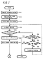
- FIG. 7 is a flow chart showing a processing procedure in the terminal device (corresponding to the terminal device M1 in FIG. 6 ) on the transmitting side of the inquiry message
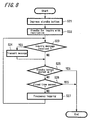
- FIG. 8 is a flow chart showing a processing procedure in the terminal device (corresponding to the terminal device M2 in FIG. 6 ) on the responding side to the inquiry message
- FIG. 9 is a flow chart showing a processing procedure of a connection on the side of the terminal device which has transmitted the inquiry message.
- Step S11 the processing procedure on the side of the terminal device which transmits the inquiry message is explained referring to FIG. 7 ; a user starts the inquiry processing by depressing the connection button 17a of the terminal device 1 (Step S11).
- the controller 13 which has detected that the connection button 17a has been depressed sends to the wireless communication unit 20 a command to set appropriate transmission power to make the message transmitted only to the close range.
- the wireless communication unit 20 performs the setting to adjust the transmission power in the transceiver 27 based on information relating to the transmission power which is stored in advance in the ROM 22, the flash memory 24 or the like. After the setting is completed, the fact is responded to the controller 13 through the input-output interface 25 (Step S12).
- the controller 13 sends to the wireless communication unit 20 a command to transmit a limited inquiry message (Step S13).
- the maximum number of devices to be discovered by the inquiry message and a period of time in which the inquiry message is continuously transmitted can be provided as parameters. In this embodiment, approximately 10 seconds is set as the time to be capable of collecting the ample number of responses from neighboring devices and one is set as the maximum number of device to be discovered.
- the wireless communication unit 20 generates a limited inquiry message in the base-band controller 26 in accordance with the command issued from the host side through the input-output interface 25, and transmits the limited inquiry message through the transceiver 27 and the antenna 19 (Step S14).
- the transmission power in the transceiver 27 at this time is set to be controlled based on information related to the transmission power which is stored in the ROM 22, the flash memory 23 or the like, and therefore, the limited inquiry message is transmitted only to the close range.
- the standby processing for the limited inquiry message starts by depressing the standby button 17b of the terminal device (Step S21).
- the controller 13 which has detected that the standby button 17b has been depressed sends to the wireless communication unit 20 a command to respond to the limited inquiry message.
- the wireless communication unit 20 awaits an inquiry message from another device at a predetermined periodical interval and at a certain frequency (Step S22).
- the wireless communication unit 20 transmits to the device a response message to the inquiry (Step S24). Further, at that time, the fact may be indicated to the user in the display 11 of the terminal device or the like to let the user push up the standby button 17a.
- the controller 13 instructs the wireless communication unit 20 to suspend the standby processing, and the wireless communication unit 20 suspends the standby processing (Step S25) to finish the standby processing for the limited inquiry message. Furthermore, if a certain predetermined time has already passed, the wireless communication unit 20 suspends the standby processing (Step S26) to finish the standby processing for the limited inquiry message.
- the wireless communication unit 20 changes the frequency for standby (Step S27) and subsequently repeats the standby processing of the limited inquiry message.
- the standby button 17b is being depressed, and also, the terminal is made to be capable of responding to the limited inquiry message during the certain predetermined period of time.
- the terminal device awaits an response message to the limited inquiry message from another device (Step S15). If a target terminal device is in a state of step S23 in the flow chart of FIG. 8 and if the device is set to receive the limited inquiry message at the same timing and at the same frequency, the wireless communication unit 20 of the target terminal device transmits the response message to the limited inquiry message through the antenna 19 (Step S24) and the wireless communication unit 20 on the side of the terminal device which has transmitted the inquiry message can receive the response message through the antenna 19.
- the response message received by the terminal device includes a specific ID (a device address in the Bluetooth® communication) capable of uniquely identifying the terminal device, which is obtained and is supplied to the host side through the input-output interface 25 (Step S16). Also, in this case, since the device which can be inquired is limited to one device, the wireless communication unit 20 ends the inquiry processing at this point of time. Moreover, at that time, the fact that the response to the inquiry has been received may be indicated to the user in the display 11 to let the user push up the connection button 17a.
- a specific ID a device address in the Bluetooth® communication
- the controller 13 instructs the wireless communication unit 20 to suspend the inquiry processing when the connection button 17a is being pushed up, and then the wireless communication unit 20 suspends the inquiry processing (Step S18) to end the transmission processing of the inquiry message. Further, if the certain predetermined time has passed, the wireless communication unit 20 suspends the inquiry processing (Step S19) to end the transmission processing of the inquiry message.
- the wireless communication unit 20 changes the frequency at the time of transmitting the message (Step S20), and subsequently the transmission processing of the limited inquiry message is repeated.
- the controller 13 stores the specific ID of the terminal device included in the response message into the RAM 15, and subsequently sends a command to the wireless communication unit 20 to return to the normal state from the state in which the command has been given to the wireless communication unit 20 at the step S12 to set to transmit only to the close range.
- the wireless communication unit 20 performs the setting such that the transmission power thereafter returns to the normal state (in other words, to be capable of performing the wireless communication in the transmission distance of 10m) based on the information relating to the transmission power, which is stored in advance in the ROM 22, the flash memory 24 or the like. After the setting is completed, the fact is responded to the controller 13 through the input-output interface 25 (Step S17).
- the terminal device of the other side can be specified uniquely from the terminal device of one side by depressing mutually the connection button 17a and the standby button 17b.
- the terminal device of the other side can be specified uniquely from the terminal device of one side, subsequently a connection from the terminal device which has transmitted the inquiry message to the terminal device which has sent back the response message, and an execution of a service can be performed.
- FIG. 9 is a flow chart showing processing procedure until the establishment of the connection and further the execution of the service, following the processing of the step S17 in the flow chart of FIG. 7 .
- the terminal device on the side which has transmitted the inquiry message is called a terminal device 1 and the terminal device on the side which has sent back the response message is called a terminal device 2.
- FIG. 11 is an example of a display on the screen of the display 11 in the terminal device 1, and it is assumed that the processing in the terminal device 1 shown in the flow charts of FIGS. 7 and 9 are being performed in the state where the display shown in FIG. 11 is performed.
- the terminal device 1 stores in the RAM 15 the specific ID of the terminal device 2 to be connected.
- the controller 13 performs the connection processing with respect to the device address which is the specific ID of the terminal device 2 and which is temporarily stored in the RAM 15 of the wireless communication unit 20 (Step S31).
- this connection processing there is a case in which connection authentication processing is required for the Bluetooth® communication depending on settings of respective devices, and this connection authentication is performed by inputting identification information called a passkey.
- the terminal device 1 searches in accordance with a predetermined protocol (called a service discovery protocol) whether the terminal device 2 provides the desired service. This is performed by transmitting a service inquiry message including a specific ID indicating a specific service (service UUID) to the terminal device 2 and by transmitting a response message to the inquiry message from the terminal device 2 (step S32).
- a service discovery protocol a predetermined protocol
- This is performed by transmitting a service inquiry message including a specific ID indicating a specific service (service UUID) to the terminal device 2 and by transmitting a response message to the inquiry message from the terminal device 2 (step S32).
- service UUID a specific ID indicating a specific service
- the ID of the service which can be used for video transfer is searched.
- the control information is stored in the ROM 14, the memory 16, the memory medium 16a or the RAM 15 together with application programs such as the video display program.
- the terminal device 2 is made to await so as to be able to respond to a specific service.
- the terminal device may be controlled to be in a state in which the service that can be used for the video transfer is awaited or to be in a state in which all services continuously available are awaited.
- the terminal device 2 may be controlled to await such that an appropriate service corresponding to a program currently executed can be performed only during the standby button 17b being depressed.
- Such control information is also stored in the ROM 14, the memory 16, the memory medium 16a or the RAM 15 together with the application programs such as the video display program.
- the terminal device 1 requests the terminal device 2 to connect to the desired service (step S34).
- this connection processing there is a case in which the connection authentication processing is required for the Bluetooth® communication depending on settings of the respective devices. This connection authentication is conventionally performed by inputting the identification information called the passkey and by inquiring the user of connection permission confirmation. Further, when it is found that the terminal device 2 does not provide the desired service at the step S33 of the flow chart in FIG. 9 , the processing of performing the connection and the service shall be ended without performing further processing.
- the terminal device 1 When the service connection is established, the terminal device 1 performs an appropriate service procedure in accordance with a status of program currently executed (step S35).
- the video file is transmitted to the terminal device 2.
- a message such as the one shown in a lower part of the display panel of FIG. 11 (for example, "# Bluetooth® transmission is available") may be indicated so that the user easily understand.
- control information is also stored in the ROM 14, the memory 16, the memory medium 16a or the RAM 15 together with application programs such as the video display program.
- the content and result of the executed service which is in this case the fact that the video data has been transmitted to the terminal device 2 is as shown for example in FIG. 12 indicated accordingly to the user on the screen formed of the display 11 in the terminal device 1.
- the fact that the video data is received from the terminal device 1 is indicated to the user accordingly.
- the received video data may be displayed immediately.
- the controller 13 instructs the wireless communication unit 20 to disconnect the communication when the service is of a type in which the wireless communication is not required to be maintained and continued thereafter (step S37).
- the service shall be continued without being disconnected.
- the wireless communication is used for the video transfer
- the wireless communication is used for the video transfer
- Such control information is also stored in the ROM 14, the memory 16, the memory medium 16a or the RAM 15 together with application programs such as the video display program.
- the limited inquiry and the response thereto can be performed in the close range; only the terminal device of the other side can be specified uniquely from the terminal device of one side; further, the connection of the wireless communication is automatically established in accordance with the executing state of the program and the standby state for the service at the respective terminal devices; and the desired service can be executed.
- the desired service is the video transfer
- the video is transferred from the terminal device of one side to the terminal device of the other side and after the transfer is completed, the disconnection processing may be performed from the terminal device of one side to the terminal device of the other side.
- FIGS. 10A and 10B are diagrams showing an example of a transmission state from starting the wireless communication until disconnecting the communication using the connection button and the standby button in two terminal devices M1 and M2 which are disposed close to each other.
- FIG. 10A when the connection button 17a of the terminal device M1 is depressed, transmission a of a limited inquiry message in a close range (short range) is performed. Then, since the standby button 17b of the terminal device M2 is being depressed as shown in FIG. 10B , a standby for receiving the limited inquiry message is performed and transmission b of a response message is performed.
- connection button 17a of the terminal device M1 users operating respective terminal devices perform an operation to stop depressing the connection button 17a of the terminal device M1 and an operation to stop depressing the standby button 17b of the terminal device M2 to enter connection processing for establishing the connection.
- transmission c from the terminal device M1 and transmission d from the terminal device M2 are performed alternately, and confirmation of an ID of the destination terminal device, an inquiry of a service and the like are performed to complete the connection.
- connection button 17a and the standby button 17b are respectively used in the processing which has been explained so far in order to instruct the terminal device of one side to perform the connection and the terminal device of the other side to perform the standby
- a button displayed on the screen of the display 11 functioning also as a touch panel may be used to be touched, for example.
- connection button 17a and the standby button 17b although the control is performed to transmit the inquiry message only during the button 17a being depressed, for example, with respect to the connection button 17a, it is possible to make the inquiry message transmitted only during a certain period of time after the connection button 17a is depressed and is released immediately, for example, or it is also possible to sequentially perform the processing of the inquiry, the connection and the service execution only during the connection button 17a being depressed, which indicates that the wireless communication is suspended immediately after the connection button 17a is released.
- the control is also performed similarly to respond to the inquiry message only during the button being depressed, it is possible to respond to the inquiry message only during a certain period of time after the standby button 17b is depressed and is released immediately, for example, or it is also possible to sequentially perform the response to the inquiry and the standby for the service only during the standby button 17b being depressed, which indicates that the Bluetooth® communication is suspended immediately after the standby button 17b is released.
- buttons of the connection button 17a and the standby button 17b are provided to make the connection button operated on the side of the terminal device which performs the inquiry and to make the standby button operated on the side of the terminal device which performs the standby; however, it is also possible to use one button in common as the connection button and the standby button, so that a operation can be performed in common on the side of the terminal device which performs the inquiry and on the side of the terminal device which performs the standby.
- connection button 17c is provided and only the connection button 17c is depressed both on the side of the terminal device which performs the inquiry and on the side of the terminal device which performs the standby.
- connection button 17c As processing at the time when the connection button 17c is depressed, transmission of a limited inquiry message which is restricted to the close range and the standby for the inquiry message are performed alternately in the respective terminal devices and a period of performing the transmission of the inquiry message and a period of performing the standby for the inquiry message are randomly set, so that when processing is performed for a certain period of time, the inquiry message transmitted from the terminal device of one side can be received by the terminal device of the other side to be able to enter the connection processing.
- FIGS. 15A and 15B are diagrams showing an example of the transmission of the above case.
- two terminal devices M1 and M2 are respectively formed as the handheld information terminal device 10' including only the connection button 17c for close range communication and the connection button 17c is depressed almost simultaneously.
- the transmission and the standby of the inquiry message are set alternately at a random cycle in the respective terminal devices M1 and M2.
- an inquiry message i which is transmitted from the terminal device M1 is received by the terminal device M2 and a response message j to the inquiry is sent back to the terminal device M1.
- connection processing (not shown in the figures) is performed.
- connection processing restricted to the close range can be performed by the operation of only one connection button which is provided in respective terminal devices, the user operating each of the terminal devices M1 and M2 is only required to operate the same button when operating either of the terminal devices, and therefore, the operation becomes simple to the extent.
- FIG. 16 shows an example of a configuration of that case.
- a mobile phone unit 301 is provided with a button group 302 capable of performing a numerical input to perform a limited inquiry message which corresponds to the numerical input and the standby therefor.
- a computer apparatus 303 is provided with a numerical key group 304 as a part of a keyboard capable of performing the numerical input to perform a limited inquiry message which corresponds to that numerical input and the standby therefor.
- FIGS. 17A to 17C are time charts showing a connection procedure when those mobile phone unit and personal computer apparatus are used.
- the terminal device M1 is the mobile phone unit 301
- the terminal device M2 is the personal computer apparatus 303
- the terminal device M3 is another computer apparatus which is not shown in the figure.
- the terminal devices M1, M2 and M3 are made to repeat the inquiry and the standby at a random cycle in accordance with the sequence shown in the embodiment explained above.
- an operation to input a specific key 1 is performed using the button group 302 in the terminal device M1, so that, a procedure, which is the procedure of a limited inquiry corresponding to the key 1 and a standby therefor, is performed ( FIG. 17A ). Also in the terminal device M2, the key 1 is similarly inputted to perform the similar procedure ( FIG. 17B ). Further, in the terminal device M3, a key 2 is inputted to perform the procedure of a limited inquiry corresponding to the key 2 and a standby therefor ( FIG. 17C ).
- the terminal devices M1 and M2 perform the same limited inquiry, similarly to the case explained in the above embodiment, the connection is established between the terminal devices M1 and M2 and a service is executed. On the other hand, since the terminal device M3 performs the limited inquiry of the different number, the connection cannot be established with the terminal devices M1 and M2.
- the processing of limiting the transmission output power on the transmitting side is performed; however another processing may be used to make the wireless communication restricted to the close range.
- the receiving sensitivity in the handheld information terminal device on the receiving side may be lowered at the time of a standby so as to make the wireless communication restricted to the close range.
- both the limitation of the transmission output power on the transmitting side and the change of the receiving sensitivity on the receiving side may be performed.
- a close range wireless communication unit such as that of the Bluetooth® communication may be incorporated in (or, externally attached to) a mobile phone unit, a digital camera, a digital video camera, a television receiver, a portable music player, a headphone and the like to perform the similar processing.
- a communication apparatus such as a handheld information terminal device is formed as a device exclusively used for communication
- a card or the like in which a circuit for data communication is incorporated, is attached to a data processing apparatus such as a personal computer apparatus for example, and a program to perform the processing explained in the above described flow charts is installed in the computer apparatus so that a system to perform the similar processing is configured.
- a communication target device can be specified by bringing the devices to be connected close to each other and by depressing buttons for the connection on both sides or the like, the communication between the specific devices can be established easily and securely.
- the communication target device can securely be specified, predetermined processing can be performed immediately in accordance with a state of a program which is being executed in the device of one side. Accordingly, in a state where a video is displayed in the device of one side for example, with depressing the button the transmission of the video or the like can be performed automatically with respect to the device which exists in the neighborhood and in which the button has been depressed similarly. Accordingly, a user can execute a specific application and service easily.
- the effectiveness can be most obtained.
- a user holds the mobile phone unit by the right hand and brings it close to the personal computer apparatus, and almost simultaneously the button of the mobile phone unit is depressed by the right hand and the button of the personal computer apparatus is depressed by the left hand to start the communication securely between the mobile phone unit and the personal computer apparatus, so that the operability is greatly improved.
Landscapes
- Engineering & Computer Science (AREA)
- Computer Networks & Wireless Communication (AREA)
- Signal Processing (AREA)
- Computer Security & Cryptography (AREA)
- Mobile Radio Communication Systems (AREA)
- Telephone Function (AREA)
Applications Claiming Priority (3)
| Application Number | Priority Date | Filing Date | Title |
|---|---|---|---|
| JP2002167746A JP3928489B2 (ja) | 2002-06-07 | 2002-06-07 | 通信方法、通信システム及び通信機器 |
| JP2002167746 | 2002-06-07 | ||
| PCT/JP2003/007135 WO2003105361A1 (ja) | 2002-06-07 | 2003-06-05 | 通信方法、通信システム及び通信機器 |
Publications (3)
| Publication Number | Publication Date |
|---|---|
| EP1513262A1 EP1513262A1 (en) | 2005-03-09 |
| EP1513262A4 EP1513262A4 (en) | 2006-05-17 |
| EP1513262B1 true EP1513262B1 (en) | 2008-05-07 |
Family
ID=29727672
Family Applications (1)
| Application Number | Title | Priority Date | Filing Date |
|---|---|---|---|
| EP03733294A Expired - Lifetime EP1513262B1 (en) | 2002-06-07 | 2003-06-05 | Communication method, communication system, and communication device |
Country Status (8)
| Country | Link |
|---|---|
| US (1) | US7076210B2 (enExample) |
| EP (1) | EP1513262B1 (enExample) |
| JP (1) | JP3928489B2 (enExample) |
| KR (1) | KR100982085B1 (enExample) |
| CN (1) | CN100483957C (enExample) |
| AU (1) | AU2003242147A1 (enExample) |
| DE (1) | DE60320785D1 (enExample) |
| WO (1) | WO2003105361A1 (enExample) |
Families Citing this family (39)
| Publication number | Priority date | Publication date | Assignee | Title |
|---|---|---|---|---|
| JP3862073B2 (ja) * | 2002-06-07 | 2006-12-27 | ソニー株式会社 | 無線通信装置および無線通信方法、記録媒体、並びにプログラム |
| JP3707449B2 (ja) * | 2002-06-10 | 2005-10-19 | ソニー株式会社 | 通信方法、通信システム及び通信機器 |
| KR100538804B1 (ko) * | 2003-11-10 | 2005-12-23 | 한국전자통신연구원 | 무선 제어 네트워크에서의 무선 디바이스 제어 장치 및 그방법 |
| JP2005286827A (ja) * | 2004-03-30 | 2005-10-13 | Denso Corp | ハンズフリー装置 |
| US20060089174A1 (en) * | 2004-04-29 | 2006-04-27 | Tapwave, Inc. | Mobile computing device with a physical button for wireless communications |
| FR2872376A1 (fr) * | 2004-06-24 | 2005-12-30 | France Telecom | Procede et dispositif de controle d'acces sans fil a des services telematiques et vocaux |
| EP1845661B1 (en) | 2005-03-10 | 2016-11-16 | Panasonic Corporation | Communication connecting method, communication connecting device and storage medium with program stored therein |
| JP2007048150A (ja) * | 2005-08-11 | 2007-02-22 | Ricoh Co Ltd | 無線通信装置、無線通信方法、無線通信プログラム、および該プログラムを記録した記録媒体 |
| JP4419936B2 (ja) * | 2005-09-13 | 2010-02-24 | 船井電機株式会社 | クライアント・サーバシステム |
| KR100836577B1 (ko) | 2006-08-08 | 2008-06-10 | 엘지전자 주식회사 | 블루투스시스템 및 그 네트워크 설정방법 |
| US7983612B2 (en) * | 2007-01-08 | 2011-07-19 | Varia Holdings Llc | Controlling of wireless connection of a portable device including an illumination component or switch |
| JP2009010786A (ja) * | 2007-06-28 | 2009-01-15 | Kyocera Corp | 通信機器、通信機器の制御方法及び通信システム |
| US7974574B2 (en) * | 2007-07-25 | 2011-07-05 | Microsoft Corporation | Base station initiated proximity service discovery and connection establishment |
| KR101236910B1 (ko) | 2007-10-09 | 2013-02-25 | 삼성전자주식회사 | 근거리 무선 통신을 통하여 다른 디바이스와 관련된 동작을수행하는 방법 및 그 장치 |
| WO2009055423A1 (en) * | 2007-10-24 | 2009-04-30 | Hmicro, Inc. | Low power radiofrequency (rf) communication systems for secure wireless patch initialization and methods of use |
| JP5217371B2 (ja) * | 2007-11-12 | 2013-06-19 | 富士通モバイルコミュニケーションズ株式会社 | 携帯電話機 |
| US7929981B2 (en) | 2008-02-27 | 2011-04-19 | Sony Ericsson Mobile Communications Ab | System and method for identifiable communication channel setup between terminals without previous contact |
| JP4613969B2 (ja) | 2008-03-03 | 2011-01-19 | ソニー株式会社 | 通信装置、及び通信方法 |
| US8606873B2 (en) | 2008-06-27 | 2013-12-10 | Qualcomm Incorporated | Methods and apparatus for securely advertising identification and/or discovery information |
| JP5084640B2 (ja) | 2008-06-30 | 2012-11-28 | キヤノン株式会社 | データ受信装置、データ送信装置、それらの制御方法及びプログラム。 |
| JP5541648B2 (ja) * | 2008-06-30 | 2014-07-09 | キヤノン株式会社 | 無線通信装置、制御方法、及びプログラム |
| WO2010075378A2 (en) | 2008-12-23 | 2010-07-01 | Interdigital Patent Holdings, Inc. | Data transfer between wireless devices |
| JP5374172B2 (ja) * | 2009-01-29 | 2013-12-25 | オリンパス株式会社 | 無線通信端末および無線ネットワークの接続設定方法 |
| JP2010283751A (ja) * | 2009-06-08 | 2010-12-16 | Canon Inc | 通信装置、通信装置の制御方法、並びにコンピュータプログラム |
| EP3595270B1 (en) * | 2009-08-21 | 2021-06-16 | Samsung Electronics Co., Ltd. | Method and apparatus for generating or using interaction activity information |
| RU2500087C2 (ru) | 2009-08-21 | 2013-11-27 | Самсунг Электроникс Ко., Лтд. | Способ и устройство для формирования или использования информации относительно интерактивных операций |
| US20110076951A1 (en) * | 2009-09-30 | 2011-03-31 | Kabushiki Kaisha Toshiba | Information processing apparatus |
| KR20110117906A (ko) * | 2010-04-22 | 2011-10-28 | 삼성전자주식회사 | 블루투스 통신 방법 및 시스템 |
| JP2011254238A (ja) * | 2010-06-01 | 2011-12-15 | Sony Corp | 情報処理装置、情報処理方法および情報処理システム |
| JP6154098B2 (ja) * | 2011-03-08 | 2017-06-28 | ソニー株式会社 | 無線通信装置、無線通信方法、及び無線通信システム |
| US9167508B2 (en) | 2011-03-08 | 2015-10-20 | Sony Corporation | Wireless communication apparatus, wireless communication method, and wireless communication system for providing improved wireless communication |
| JP5810820B2 (ja) * | 2011-10-14 | 2015-11-11 | セイコーエプソン株式会社 | 無線通信装置及び電子機器 |
| US9014681B2 (en) | 2011-12-27 | 2015-04-21 | Sony Corporation | Establishing a communication connection between two devices based on device displacement information |
| JP2013157969A (ja) | 2012-02-01 | 2013-08-15 | Hitachi Consumer Electronics Co Ltd | 携帯端末装置及びデータ送受信システム |
| US20130205352A1 (en) * | 2012-02-02 | 2013-08-08 | Aereo, Inc. | System and Method for Video Streaming to Display Device Using Parasitically Powered Receiver |
| EP2817972B8 (en) | 2012-02-21 | 2019-06-12 | InterDigital CE Patent Holdings | Methods for distributing content in multi-room environment |
| US8892042B2 (en) * | 2012-06-08 | 2014-11-18 | Apple Inc. | Immediate connection following device discovery |
| JP2014086763A (ja) * | 2012-10-19 | 2014-05-12 | Nec Access Technica Ltd | ホームゲートウェイの設定引継方法、ホームゲートウェイ、及びプログラム |
| JP6075140B2 (ja) * | 2013-03-22 | 2017-02-08 | カシオ計算機株式会社 | ペアリング方法及び電子機器 |
Family Cites Families (19)
| Publication number | Priority date | Publication date | Assignee | Title |
|---|---|---|---|---|
| US5481757A (en) * | 1992-10-26 | 1996-01-02 | Sanyo Electric Co., Ltd. | CATV terminal device in two-way communication CATV system |
| US5680419A (en) * | 1994-08-02 | 1997-10-21 | Ericsson Inc. | Method of and apparatus for interference rejection combining in multi-antenna digital cellular communications systems |
| US5453982A (en) * | 1994-08-29 | 1995-09-26 | Hewlett-Packard Company | Packet control procedure between a host processor and a peripheral unit |
| SE510393C2 (sv) * | 1997-06-26 | 1999-05-17 | Ericsson Telefon Ab L M | Förfarande och anordning för detektering av en icke auktoriserad användaraccess till ett kommunikationsnätverk |
| IL121427A0 (en) * | 1997-07-30 | 1998-01-04 | S H F Computers Software Servi | System and method for off-line notifying a network user |
| US6078826A (en) * | 1998-05-29 | 2000-06-20 | Ericsson Inc. | Mobile telephone power savings method and apparatus responsive to mobile telephone location |
| US6148205A (en) | 1998-06-30 | 2000-11-14 | Motorola, Inc. | Method and apparatus for secure registration within an in-home wireless network |
| US6219540B1 (en) * | 1998-11-23 | 2001-04-17 | Motorola, Inc. | Communication device providing out-of-range battery saving and method therefor |
| US6236835B1 (en) * | 1998-12-21 | 2001-05-22 | Motorola | Method for acquiring a predetermined type of information from a selective call device in a communication system |
| JP4167367B2 (ja) | 1999-11-18 | 2008-10-15 | 株式会社東芝 | 通信システム、通信装置、及び通信方法 |
| GB2362542A (en) * | 2000-05-05 | 2001-11-21 | Nokia Mobile Phones Ltd | Establishing communications with a proximate wireless device |
| US6792247B2 (en) * | 2000-05-08 | 2004-09-14 | Microtune (San Diego), Inc. | Co-located frequency-agile system and method |
| FR2817420B1 (fr) * | 2000-11-29 | 2003-03-07 | Sagem | Procede de communication radiofrequence |
| US6826387B1 (en) * | 2000-11-30 | 2004-11-30 | Palmsource, Inc. | Efficient service registration for legacy applications in a bluetooth environment |
| US6879810B2 (en) * | 2000-12-20 | 2005-04-12 | Nokia Corporation | Control of short range RF communication |
| US6865371B2 (en) * | 2000-12-29 | 2005-03-08 | International Business Machines Corporation | Method and apparatus for connecting devices via an ad hoc wireless communication network |
| US6842460B1 (en) * | 2001-06-27 | 2005-01-11 | Nokia Corporation | Ad hoc network discovery menu |
| JP3865124B2 (ja) | 2002-01-22 | 2007-01-10 | ソニー株式会社 | 無線通信装置および通信相手探索方法 |
| JP2003218733A (ja) | 2002-01-28 | 2003-07-31 | Alps Electric Co Ltd | 短距離無線伝送装置 |
-
2002
- 2002-06-07 JP JP2002167746A patent/JP3928489B2/ja not_active Expired - Lifetime
-
2003
- 2003-06-05 EP EP03733294A patent/EP1513262B1/en not_active Expired - Lifetime
- 2003-06-05 WO PCT/JP2003/007135 patent/WO2003105361A1/ja not_active Ceased
- 2003-06-05 AU AU2003242147A patent/AU2003242147A1/en not_active Abandoned
- 2003-06-05 CN CNB038173239A patent/CN100483957C/zh not_active Expired - Fee Related
- 2003-06-05 US US10/516,974 patent/US7076210B2/en not_active Expired - Lifetime
- 2003-06-05 DE DE60320785T patent/DE60320785D1/de not_active Expired - Lifetime
- 2003-06-05 KR KR1020047019805A patent/KR100982085B1/ko not_active Expired - Fee Related
Also Published As
| Publication number | Publication date |
|---|---|
| CN1669231A (zh) | 2005-09-14 |
| EP1513262A1 (en) | 2005-03-09 |
| JP3928489B2 (ja) | 2007-06-13 |
| JP2004015558A (ja) | 2004-01-15 |
| US20050202782A1 (en) | 2005-09-15 |
| US7076210B2 (en) | 2006-07-11 |
| KR20050004912A (ko) | 2005-01-12 |
| EP1513262A4 (en) | 2006-05-17 |
| CN100483957C (zh) | 2009-04-29 |
| AU2003242147A1 (en) | 2003-12-22 |
| DE60320785D1 (de) | 2008-06-19 |
| WO2003105361A1 (ja) | 2003-12-18 |
| KR100982085B1 (ko) | 2010-09-13 |
| WO2003105361B1 (fr) | 2004-05-13 |
Similar Documents
| Publication | Publication Date | Title |
|---|---|---|
| EP1513262B1 (en) | Communication method, communication system, and communication device | |
| EP1513291B1 (en) | Communication method, communication system, and communication device | |
| US7127210B2 (en) | Wireless communication apparatus | |
| CN100375146C (zh) | 图像显示装置、图像显示系统、及图像显示方法 | |
| JP5168383B2 (ja) | 無線通信装置及びプログラム | |
| KR101964077B1 (ko) | 휴대용 단말기에서 블루투스 디바이스와 연결하기 위한 장치 및 방법 | |
| US20020065065A1 (en) | Method and system for applying line of sight IR selection of a receiver to implement secure transmission of data to a mobile computing device via an RF link | |
| US20040162027A1 (en) | Bluetooth wireless communication apparatus and method of notifying users of devices connectable to ad-hoc networks to establish effective connections based on a user's selection | |
| KR100389820B1 (ko) | 블루투스 무선 통신을 이용한 블루투스 장치간 링크 설정방법 | |
| EP2645812A2 (en) | Communication device | |
| JP2010245748A (ja) | 無線通信システム及び無線通信方法 | |
| KR20100053759A (ko) | 무선 통신 장치들간의 페어링 방법 및 이를 위한 장치 | |
| EP1738529A1 (en) | A communication control method and wireless communication apparatus | |
| TW201330566A (zh) | 促進無線通信的系統與方法 | |
| EP2235879B1 (en) | Communication parameter setting | |
| EP1803254B1 (en) | Radio communication apparatus and control method thereof | |
| KR100612696B1 (ko) | 블루투스망에서 이동통신단말을 페어링하기 위한 방법 및이를 위한 이동통신단말 | |
| EP2235880B1 (en) | Communication parameter setting apparatus and control method therefore | |
| KR101921142B1 (ko) | 와이파이 네트워크를 연결하는 장치 및 방법 | |
| KR20260005777A (ko) | 통신 장치, 제어 방법, 및 프로그램 | |
| JP2015050721A (ja) | 外部記憶装置、データファイル送受信システム、データファイル送受信方法・プログラム |
Legal Events
| Date | Code | Title | Description |
|---|---|---|---|
| PUAI | Public reference made under article 153(3) epc to a published international application that has entered the european phase |
Free format text: ORIGINAL CODE: 0009012 |
|
| 17P | Request for examination filed |
Effective date: 20041224 |
|
| AK | Designated contracting states |
Kind code of ref document: A1 Designated state(s): AT BE BG CH CY CZ DE DK EE ES FI FR GB GR HU IE IT LI LU MC NL PT RO SE SI SK TR |
|
| AX | Request for extension of the european patent |
Extension state: AL LT LV MK |
|
| DAX | Request for extension of the european patent (deleted) | ||
| RBV | Designated contracting states (corrected) |
Designated state(s): DE FR GB |
|
| A4 | Supplementary search report drawn up and despatched |
Effective date: 20060404 |
|
| 17Q | First examination report despatched |
Effective date: 20060803 |
|
| 17Q | First examination report despatched |
Effective date: 20060803 |
|
| GRAP | Despatch of communication of intention to grant a patent |
Free format text: ORIGINAL CODE: EPIDOSNIGR1 |
|
| GRAS | Grant fee paid |
Free format text: ORIGINAL CODE: EPIDOSNIGR3 |
|
| GRAA | (expected) grant |
Free format text: ORIGINAL CODE: 0009210 |
|
| AK | Designated contracting states |
Kind code of ref document: B1 Designated state(s): DE FR GB |
|
| REG | Reference to a national code |
Ref country code: GB Ref legal event code: FG4D |
|
| REF | Corresponds to: |
Ref document number: 60320785 Country of ref document: DE Date of ref document: 20080619 Kind code of ref document: P |
|
| PLBE | No opposition filed within time limit |
Free format text: ORIGINAL CODE: 0009261 |
|
| STAA | Information on the status of an ep patent application or granted ep patent |
Free format text: STATUS: NO OPPOSITION FILED WITHIN TIME LIMIT |
|
| 26N | No opposition filed |
Effective date: 20090210 |
|
| REG | Reference to a national code |
Ref country code: GB Ref legal event code: 746 Effective date: 20120702 |
|
| REG | Reference to a national code |
Ref country code: DE Ref legal event code: R084 Ref document number: 60320785 Country of ref document: DE Effective date: 20120614 |
|
| PGFP | Annual fee paid to national office [announced via postgrant information from national office to epo] |
Ref country code: FR Payment date: 20120705 Year of fee payment: 10 Ref country code: GB Payment date: 20120622 Year of fee payment: 10 |
|
| GBPC | Gb: european patent ceased through non-payment of renewal fee |
Effective date: 20130605 |
|
| REG | Reference to a national code |
Ref country code: FR Ref legal event code: ST Effective date: 20140228 |
|
| PG25 | Lapsed in a contracting state [announced via postgrant information from national office to epo] |
Ref country code: GB Free format text: LAPSE BECAUSE OF NON-PAYMENT OF DUE FEES Effective date: 20130605 |
|
| PG25 | Lapsed in a contracting state [announced via postgrant information from national office to epo] |
Ref country code: FR Free format text: LAPSE BECAUSE OF NON-PAYMENT OF DUE FEES Effective date: 20130701 |
|
| PGFP | Annual fee paid to national office [announced via postgrant information from national office to epo] |
Ref country code: DE Payment date: 20140619 Year of fee payment: 12 |
|
| REG | Reference to a national code |
Ref country code: DE Ref legal event code: R119 Ref document number: 60320785 Country of ref document: DE |
|
| PG25 | Lapsed in a contracting state [announced via postgrant information from national office to epo] |
Ref country code: DE Free format text: LAPSE BECAUSE OF NON-PAYMENT OF DUE FEES Effective date: 20160101 |