EP1512904A2 - Scheinwerfer für Fahrzeuge - Google Patents
Scheinwerfer für Fahrzeuge Download PDFInfo
- Publication number
- EP1512904A2 EP1512904A2 EP04020697A EP04020697A EP1512904A2 EP 1512904 A2 EP1512904 A2 EP 1512904A2 EP 04020697 A EP04020697 A EP 04020697A EP 04020697 A EP04020697 A EP 04020697A EP 1512904 A2 EP1512904 A2 EP 1512904A2
- Authority
- EP
- European Patent Office
- Prior art keywords
- reflector
- diaphragm shaft
- bearing shell
- bearing
- holder
- Prior art date
- Legal status (The legal status is an assumption and is not a legal conclusion. Google has not performed a legal analysis and makes no representation as to the accuracy of the status listed.)
- Granted
Links
- 238000005096 rolling process Methods 0.000 claims description 10
- 230000003287 optical effect Effects 0.000 claims description 7
- 229910052751 metal Inorganic materials 0.000 claims description 6
- 239000002184 metal Substances 0.000 claims description 6
- 230000005540 biological transmission Effects 0.000 claims description 3
- 230000002452 interceptive effect Effects 0.000 claims description 3
- 230000001747 exhibiting effect Effects 0.000 claims description 2
- 229910000838 Al alloy Inorganic materials 0.000 description 2
- FYYHWMGAXLPEAU-UHFFFAOYSA-N Magnesium Chemical compound [Mg] FYYHWMGAXLPEAU-UHFFFAOYSA-N 0.000 description 2
- 229910000861 Mg alloy Inorganic materials 0.000 description 2
- 238000004512 die casting Methods 0.000 description 2
- 239000011777 magnesium Substances 0.000 description 2
- 230000001154 acute effect Effects 0.000 description 1
- 238000013459 approach Methods 0.000 description 1
- 230000015572 biosynthetic process Effects 0.000 description 1
- 238000001746 injection moulding Methods 0.000 description 1
- 230000001788 irregular Effects 0.000 description 1
Images


Classifications
-
- F—MECHANICAL ENGINEERING; LIGHTING; HEATING; WEAPONS; BLASTING
- F21—LIGHTING
- F21S—NON-PORTABLE LIGHTING DEVICES; SYSTEMS THEREOF; VEHICLE LIGHTING DEVICES SPECIALLY ADAPTED FOR VEHICLE EXTERIORS
- F21S41/00—Illuminating devices specially adapted for vehicle exteriors, e.g. headlamps
- F21S41/60—Illuminating devices specially adapted for vehicle exteriors, e.g. headlamps characterised by a variable light distribution
- F21S41/68—Illuminating devices specially adapted for vehicle exteriors, e.g. headlamps characterised by a variable light distribution by acting on screens
- F21S41/683—Illuminating devices specially adapted for vehicle exteriors, e.g. headlamps characterised by a variable light distribution by acting on screens by moving screens
- F21S41/698—Shaft-shaped screens rotating along its longitudinal axis
Definitions
- the invention relates to a headlamp for vehicles with a cast cup-shaped reflector having an inner and outer focal point, with a diaphragm shaft arranged between a lens and the reflector, the axis of rotation about a horizontal and transverse to the optical axis is adjustable in several rotational positions for different light functions, and with a holder attached to the front edge portion of the reflector for at least one storage means of the diaphragm shaft.
- From DE - A - 199 21 907 is a headlamp for vehicles with a two Known burner dish-shaped reflector, which is a lens and a diaphragm shaft are assigned.
- the aperture shaft extends transversely to the optical axis arranged in the apex region of the reflector Light source.
- the diaphragm shaft is rotatably supported about its axis of rotation and has encircling an outwardly curved lateral surface with several focal lines depending on the rotational position of the diaphragm shaft to the formation of light-dark boundaries serve different light figures.
- the aperture shaft points Burning lines for symmetrical and asymmetrical dipped beam and high beam on.
- the Aperture shaft is with its storage means at both end areas in Bearing openings of a holder mounted on the front edge of the area Reflector is attached. On the holder is the side with the aperture shaft coupled drive means attached.
- the drive means consists of a motor and a gearbox. The disadvantage here is that the location of storage and thus the diaphragm shaft is fixed exclusively by the holder.
- the tolerance chain to the reflection surface of the Reflectors should be so large that the aperture is not optimal to the Reflection surface is positioned and thus the below a cut-off line the dimmed light figures prescribed and desired high light values are not more than sufficiently large.
- the tolerance chain to the reflection surface of the Reflectors should be so large that the aperture is not optimal to the Reflection surface is positioned and thus the below a cut-off line the dimmed light figures prescribed and desired high light values are not more than sufficiently large.
- From DE - A - 100 47 207 is a headlamp for vehicles with a Aperture shaft known to be connected to the front edge of the area Reflektors in the application neither described nor clearly illustrated.
- the object of the invention is the, in the preamble of claim 1 described headlights for vehicles to improve such that at a simply constructed headlight after the assembly of the diaphragm shaft their exact positioning to the reflection surface of the reflector is safe.
- the object is achieved according to the invention in that the front Edge portion of the reflector fastened holder with a section one Bearing shell of the front edge area spans and the storage means the diaphragm shaft holds radially in the bearing shell without clearance radially to the axis of rotation.
- the cast reflector is made in one piece and diecasting for Example of a magnesium or aluminum alloy or by means Injection molding made of plastic.
- the aperture is exactly to Reflection surface of the reflector positioned as the bearing shell of the reflector and its reflection surface together by an adjustable tool part are demoldable and the holder holds the diaphragm shaft to the bearing shell.
- the Aperture also exactly to the adjacent outer focal point of the reflector arranged and below the cut-off line of each generated light figure reaches optimal light levels.
- the exact positioning of the aperture shaft to the outer focal point the reflector no disturbing color fringing at the cut-off of the Light figure.
- the bearing shell of the reflector spanning portion of the holder under pretension on the Storing means of the diaphragm shaft and presses the storage means against the Bearing shell, wherein the bearing shell of the reflector a two-point system defining positioning surfaces for the storage means of the diaphragm shaft has and a plant side of the bearing shell of the reflector spanning section of the holder together with the Positioning surfaces of the bearing shell of the reflector a three-point system for defines the storage means of the diaphragm shaft.
- This is the aperture shaft arranged very precisely to the outer focal point of the elliptical reflector and safe in all directions transverse to the axis of rotation backlash on the bearing shell held.
- a the Storage means adjacent to the axis of rotation fixing abutment surface adjacent is arranged. It can also be on both sides of the two Positioning surfaces are each arranged a contact surface, the together form a groove and the storage means of the diaphragm shaft between to record oneself.
- the diaphragm shaft is rotatable smoothly when the storage means of Aperture shaft placed on a journal of the diaphragm shaft Rolling bearing has.
- the shielding means of the shutter shaft is protected against damage is arranged and securely held when the holder forms a bearing shell, the together with the bearing shell of the reflector, a bearing opening for the Storage means of the diaphragm shaft is and the bearing shell of the holder a radial inward and the contact surface for the three-point system having exhibiting contact element.
- the holder can cost-effectively from a Be punched sheet metal blank, wherein the contact element from the holder bent sheet metal section is.
- the diaphragm shaft is provided with a Storage means at a free end portion by the holder and the Bearing shell of the reflector radially and axially supported while the Shield shaft with the other free end section in one on the reflector salaried drive means of the diaphragm shaft supported radially to the axis of rotation and is mounted axially floating. This allows between the aperture shaft and the drive means no tensions occur.
- the aperture is held by the drive means exactly to the outer focal point of the reflector, when the drive means between the front and back of the reflector on a reflector side are attached to holding elements of the reflector, wherein Positioning means of reflector parallel to the rotation axis of the shutter shaft and drive means are inserted into each other, which holds the diaphragm shaft holder Position the drive unit towards the reflecting surface of the reflector.
- the diaphragm shaft each arranged with one at its two end portions Storage means supported by the holder in a bearing shell of the reflector is, wherein an end portion of the diaphragm shaft with one on the reflector arranged drive means is coupled via a transmission.
- Another particular advantage of the invention is that the holder the Light exit opening of the reflector surrounds and both for holding the Headlamps as well as a Abschatters, which adjacent to Aperture shaft extends and at least in a rotational position of the diaphragm shaft shields interfering light rays together with the aperture. This is for the holder of the diaphragm shaft no separate part necessary.
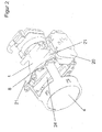
- a headlight for vehicles shown in FIGS. 1 and 2 is designed as a projection module that has an elliptical reflector 1, a light source 28 arranged in the apex region of the reflector 1, a lens 4 and a diaphragm shaft 5 arranged between the reflector 1 and the lens 2.
- the lens 2 is inserted into a table-shaped frame 25 which is fixed to the front edge region 8 of the reflector 1.
- the reflector 1 has an inner and outer focal point 2 and 3.
- the inner focal point, the light source 28 and the outer focal point 3, the middle upper portion of the diaphragm shaft 5 is assigned.
- the light source 28 is a high-pressure gas discharge lamp, which carries an ignition device 27 at its base.
- the diaphragm shaft 5 is by die casting for example of a magnesium or Aluminum alloy produced. It can also be made from an elongated one Hollow body made of sheet metal, wherein the contour of the lateral surface of the Hollow body is produced by generating an internal high pressure (not ) Shown. At its free end portions, the diaphragm shaft 5 respectively Storage means 10, with which the diaphragm shaft 5 at the front Edge region 8 of the reflector 1 is mounted.
- the diaphragm shaft 5 is perpendicular to the optical axis 6 of the headlight in stored horizontally.
- An end portion of the diaphragm shaft 5 is with a motor (not shown) serving as drive means 20, by means of which the diaphragm shaft 5 can be brought into predetermined rotational positions is.
- a control electronics for the motor is integrated in the drive means 20.
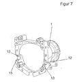
- the drive means 20 has a housing which on holding elements 21 of the Reflektors 1 is attached.
- the holding element 21 are connected to the reflector 1 molded-on approaches to which by means of screws or rivets Drive means 20 on the reflector 1 can be fixed.
- the drive means 20 and thus the holding elements 21 are between the front and rear side of the Reflectors 1 arranged.
- the reflector 1 has two opposite each other Side holding elements 21, so that the drive means 20 optionally on both Side of the reflector 1 can be attached.
- the lateral surfaces of the diaphragm shaft 5 is formed such that in different adjusted about the axis of rotation 7 of the diaphragm shaft 5 Turning positions focal lines 8 of the optical light system are formed, by means of their light-dark borders differentiated dimmed light figures such as symmetrical and asymmetrical low beam for Right and left traffic are generated.
- the lateral surface of the diaphragm shaft. 5 is curved at least in the area having the focal lines formed and has at least one two focal lines running Surface portion formed differently from a cylindrical surface is.
- the lateral surface of the diaphragm shaft 5 thus extends in the surface section irregular (not shown). Furthermore, the lateral surface of the Aperture 5 a flattening for high beam on (not shown).
- a frame-like holder 9 is arranged, the on the side facing the lens 4 of the front edge region 8 abuts.
- the frame-like holder 9 is punched out of a sheet metal blank and has in Area of the diaphragm shaft 5 a shading 24, which together with the Shutter wave 5 interfering light rays shields.
- the shader 24 is executed strip-shaped and runs in its longitudinal extent parallel to Rotation axis 7 of the diaphragm shaft 5.
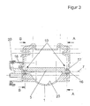
- the axis of rotation 7 is defined by the Storage means 10 of the diaphragm shaft 5, the two free end portions the diaphragm shaft 5 are arranged.
- the two storage means 10 each have a bearing pin 16, whose central axis is the axis of rotation 7.
- the Storage means 10, which is further away from the drive means 20 points a pushed onto the bearing pin 16 in a press fit rolling bearing 17.
- the rolling bearing 17 engages in a bearing shell 12 of the reflector 1 and is applied two positioning surfaces 13 of the bearing shell 12 at.
- the Positioning surfaces 13 are at an acute angle to each other and fix the diaphragm shaft very precisely to the reflection surface 23 of the reflector 1.
- Each on both sides of the positioning surfaces 13, the Bearing shell 12 of the reflector 1 contact surfaces 15, which together with the Positioning surfaces 13 form a receiving groove for the rolling bearing 17.
- the Contact surfaces 15 fix the diaphragm shaft 5 in their longitudinal extent.
- the Bearing shell 12 of the reflector 1 and the reflection surface 23 of the reflector first are demolded together from a tool part.
- the bearing shell 12 of Reflektors 1 In the bearing shell 12 of Reflektors 1 is the rolling bearing 17 through a bearing shell 12th spanning portion 11 of the holder 9 held.
- the section 11 forms also a bearing shell 18, which together with the bearing shell 12 of the Reflektors 1 form a bearing opening for the rolling bearing 17.
- the section 11 has an investment element 19 pushed out of its central area on, the biased with an abutment side 14 on the roller bearing 17th abuts and together with the positioning surfaces 13 a three-point system for the rolling bearing 17 forms.
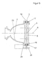
- the diaphragm shaft 5 is in the range of Drive means 20 with its bearing journal 16 axially floating in one Bearing of the drive means 20 stored.
- the drive means 20 and the Reflector 1 have interlocking positioning means 22 through which the diaphragm shaft 5 is fixed exactly to the reflection surface 23 of the reflector 1 is held.
- the positioning means 22 consist of pins of the Drive means 20, the backlash in corresponding holes of the reflector 1 intervention.
- the plugging direction of the positioning means 22 runs parallel to The axis of rotation 7 of the diaphragm shaft 5.
- the reflector 1 and the holder 9 have the side of the drive means 20 and an unused bearing shell 12 and 18 on. This and because the reflector on the other side Holding elements 21 and positioning means 22 for the drive means 20th can, the drive means 20 and the rolling bearing 17 optionally on the one or the other side of the reflector 1 are mounted.
- both Storage means 10 of the diaphragm shaft 5 each have a rolling bearing 17, which in each held a Lagerschlager 12 of the reflector 1 by the holder 9 are.
- the drive means 21 of the reflector 1 mounted drive means 20th is coupled via a gear 26 with the diaphragm shaft 5.
Landscapes
- Engineering & Computer Science (AREA)
- General Engineering & Computer Science (AREA)
- Non-Portable Lighting Devices Or Systems Thereof (AREA)
- Lighting Device Outwards From Vehicle And Optical Signal (AREA)
Abstract
Description
Der Reflektor 1 weist einen inneren und äußeren Brennort 2 und 3 auf. Dem inneren Brennort ist die Lichtquelle 28 und dem äußeren Brennort 3 der mittlere obere Abschnitt der Blendenwelle 5 zugeordnet. Als Lichtquelle 28 dient eine Hochdruckgasentladungslampe, die an ihrem Sockel eine Zündeinrichtung 27 trägt.
- 1.
- Reflektor
- 2.
- innerer Brennort
- 3.
- äußerer Brennort
- 4.
- Linse
- 5.
- Blendenwelle
- 6.
- optische Achse
- 7.
- Drehachse
- 8.
- vordere Randbereich des Reflektors
- 9.
- Halter
- 10.
- Lagerungsmittel
- 11.
- Abschnitt des Halters
- 12.
- Lagerschale des Reflektors
- 13.
- Positionierungsflächen der Lagerschale
- 14.
- Anlageseite des Abschnitts des Halters
- 15.
- Anlagefläche der Lagerschale
- 16.
- Lagerzapfen
- 17.
- Wälzlager
- 18.
- Lagerschale des Halters
- 19.
- Anlageelement des Halters
- 20.
- Antriebsmittel
- 21.
- Halteelemente des Reflektors
- 22.
- Positionierungsmittel
- 23.
- Reflexionsfläche
- 24.
- Abschatter
- 25.
- tischförmiges Gestell
- 26.
- Getriebe
- 27.
- Zündeinrichtung
- 28.
- Lichtquelle
Claims (13)
- Scheinwerfer für Fahrzeuge mit einem gegossenen schalenförmigen Reflektor (1), der einen inneren und äußeren Brennort (2 und 3) aufweist, mit einer zwischen einer Linse (4) und dem Reflektor (1) angeordneten Blendenwelle (5), die um eine horizontale und quer zur optischen Achse (6) verlaufenden Drehachse (7) in mehrere Drehstellungen für unterschiedliche Lichtfunktionen verstellbar ist, und mit einem an dem vorderen Randbereich (8) des Reflektors (1) befestigten Halter (9) für mindestens ein Lagerungsmittel (10) der Blendenwelle (5), dadurch gekennzeichnet, dass der an dem vorderen Randbereich (8) des Reflektors (1) befestigte Halter (9) mit einem Abschnitt (11) eine Lagerschale (12) des vorderen Randbereichs (8) überspannt und das Lagerungsmittel (10) der Blendenwelle (5) radial zur Drehachse (7) spielfrei in der Lagerschale (12) haltert.
- Scheinwerfer nach Anspruch 1, dadurch gekennzeichnet, dass der gegossene Reflektor (1) aus ein Leichtmetall-Druckguss oder Kunststoff besteht.
- Scheinwerfer nach Anspruch 1 oder 2, dadurch gekennzeichnet, dass der die Lagerschale (12) des Reflektors (1) überspannende Abschnitt (11) des Halters (9) unter Vorspannung an dem Lagerungsmittel (10) der Blendenwelle (5) anliegt und das Lagerungsmittel (10) gegen die Lagerschale (12) drückt.
- Scheinwerfer nach einem der Ansprüche 1 bis 3, dadurch gekennzeichnet, dass die Lagerschale (12) des Reflektors (1) eine Zweipunktanlage definierende Positionierungsflächen (13) für das Lagerungsmittel (10) der Blendenwelle (5) aufweist.
- Scheinwerfer nach Anspruch 4, dadurch gekennzeichnet, dass eine Anlageseite (14) des die Lagerschale (12) des Reflektors (1) überspannenden Abschnitts (11) des Halters (9) zusammen mit den Positionierungsflächen (13) der Lagerschale (12) des Reflektors (1) eine Dreipunktanlage für das Lagerungsmittel (10) der Blendenwelle (5) definiert.
- Scheinwerfer nach Anspruch 4 oder 5, dadurch gekennzeichnet, dass mindestens zu einer der beiden Positionierungsflächen (13) der Zweipunktanlage eine das Lagerungsmittel (10) in Richtung der Drehachse (7) fixierende Anlagefläche (15) benachbart angeordnet ist.
- Scheinwerfer nach einem vorstehenden Ansprüche 1 bis 6, dadurch gekennzeichnet, dass das Lagerungsmittel (10) der Blendenwelle (5) ein auf einen Lagerzapfen (16) der Blendenwelle (5) aufgesetztes Wälzlager (17) aufweist.
- Scheinwerfer nach einem der Ansprüche 1 bis 7, dadurch gekennzeichnet, dass der Halter (9) eine Lagerschale (18) bildet, die zusammen mit der Lagerschale (12) des Reflektors (1) eine Lageröffnung für das Lagerungsmittel (10) der Blendenwelle (5) ist.
- Scheinwerfer nach Anspruch 8, dadurch gekennzeichnet, dass die Lagerschale (18) des Halters (9) ein radial nach innen gerichtetes und die Anlageseite (14) für die Dreipunktanlage aufweisendes Anlageelement (19) aufweist.
- Scheinwerfer nach einem der vorstehenden Ansprüche 1 bis 9, dadurch gekennzeichnet, dass die Blendenwelle (5) mit einem Lagerungsmittel (10) an einem freien Endabschnitt durch den Halter (9) und die Lagerschale (12) des Reflektors (1) radial und axial gehaltert ist, während die Blendenwelle (5) mit dem anderen freien Endabschnitt in einem am Reflektor (1) gehalterten Antriebsmittel (20) der Blendenwelle (5) radial zur Drehachse (7) gehaltert und axial schwimmend gelagert ist.
- Scheinwerfer nach Anspruch 10, dadurch gekennzeichnet, dass das Antriebsmittel (20) zwischen der Vorder- und Rückseite des Reflektors (1) an einer Reflektorseite an Halteelementen (21) des Reflektors (1) befestigt sind, wobei parallel zur Drehachse (7) der Blendenwelle (5) ineinandergesteckte Positionierungsmittel (22) von Reflektor (1) und Antriebsmittel (20) ineinandergesteckt sind, die das die Blendenwelle (5) halternde Antriebsmittel (20) zur Reflexionsfläche (23) des Reflektors (1) positionieren.
- Scheinwerfer nach einem der Ansprüche 1 bis 11, dadurch gekennzeichnet, dass der Halter (9) aus Blech besteht, die Lichtaustrittsöffnung des Reflektors (1) umgibt und sowohl zur Halterung des Scheinwerfers als auch eines Abschatters (24) dient, der benachbart zur Blendenwelle (5) verläuft und zumindest in einer Drehstellung der Blendenwelle (5) zusammen mit der Blendenwelle (5) störende Lichtstrahlen abschirmt.
- Scheinwerfer nach einem oder mehreren der vorstehenden Ansprüche, dadurch gekennzeichnet, dass die Blendenwelle mit jeweils einem an ihren beiden Endabschnitten angeordneten Lagerungsmittel von dem Halter in einer Lagerschale des Reflektors gehaltert ist, wobei ein Endabschnitt der Blendenwelle mit einem am Reflektor angeordneten Antriebsmittel über ein Getriebe gekoppelt ist.
Applications Claiming Priority (2)
| Application Number | Priority Date | Filing Date | Title |
|---|---|---|---|
| DE10340962 | 2003-09-05 | ||
| DE10340962A DE10340962A1 (de) | 2003-09-05 | 2003-09-05 | Scheinwerfer für Fahrzeuge |
Publications (3)
| Publication Number | Publication Date |
|---|---|
| EP1512904A2 true EP1512904A2 (de) | 2005-03-09 |
| EP1512904A3 EP1512904A3 (de) | 2007-12-19 |
| EP1512904B1 EP1512904B1 (de) | 2010-01-20 |
Family
ID=34129661
Family Applications (1)
| Application Number | Title | Priority Date | Filing Date |
|---|---|---|---|
| EP04020697A Expired - Lifetime EP1512904B1 (de) | 2003-09-05 | 2004-09-01 | Scheinwerfer für Fahrzeuge |
Country Status (3)
| Country | Link |
|---|---|
| EP (1) | EP1512904B1 (de) |
| AT (1) | ATE456001T1 (de) |
| DE (2) | DE10340962A1 (de) |
Cited By (1)
| Publication number | Priority date | Publication date | Assignee | Title |
|---|---|---|---|---|
| WO2010031743A1 (de) * | 2008-09-16 | 2010-03-25 | Hella Kgaa Hueck & Co. | Scheinwerfer für fahrzeuge und herstellungsverfahren für blendeneinrichtung |
Families Citing this family (1)
| Publication number | Priority date | Publication date | Assignee | Title |
|---|---|---|---|---|
| DE102005021705A1 (de) * | 2005-05-11 | 2006-11-16 | Hella Kgaa Hueck & Co. | Projektionsscheinwerfer für Fahrzeuge |
Citations (2)
| Publication number | Priority date | Publication date | Assignee | Title |
|---|---|---|---|---|
| DE19921907A1 (de) | 1999-05-12 | 2000-11-16 | Hella Kg Hueck & Co | Scheinwerfer für Fahrzeuge |
| DE10047207A1 (de) | 2000-09-23 | 2002-04-11 | Hella Kg Hueck & Co | Scheinwerfer für Fahrzeuge |
Family Cites Families (3)
| Publication number | Priority date | Publication date | Assignee | Title |
|---|---|---|---|---|
| US5373424A (en) * | 1992-10-21 | 1994-12-13 | Koito Manufacturing Co., Ltd. | Automotive projection headlamp |
| FR2721686B1 (fr) * | 1994-06-28 | 1996-09-13 | Valeo Vision | Projecteur du type elliptique, comportant un cache basculant. |
| DE19739089A1 (de) * | 1997-09-06 | 1999-03-11 | Hella Kg Hueck & Co | Scheinwerfer für Fahrzeuge |
-
2003
- 2003-09-05 DE DE10340962A patent/DE10340962A1/de not_active Withdrawn
-
2004
- 2004-09-01 DE DE502004010663T patent/DE502004010663D1/de not_active Expired - Lifetime
- 2004-09-01 AT AT04020697T patent/ATE456001T1/de not_active IP Right Cessation
- 2004-09-01 EP EP04020697A patent/EP1512904B1/de not_active Expired - Lifetime
Patent Citations (2)
| Publication number | Priority date | Publication date | Assignee | Title |
|---|---|---|---|---|
| DE19921907A1 (de) | 1999-05-12 | 2000-11-16 | Hella Kg Hueck & Co | Scheinwerfer für Fahrzeuge |
| DE10047207A1 (de) | 2000-09-23 | 2002-04-11 | Hella Kg Hueck & Co | Scheinwerfer für Fahrzeuge |
Cited By (1)
| Publication number | Priority date | Publication date | Assignee | Title |
|---|---|---|---|---|
| WO2010031743A1 (de) * | 2008-09-16 | 2010-03-25 | Hella Kgaa Hueck & Co. | Scheinwerfer für fahrzeuge und herstellungsverfahren für blendeneinrichtung |
Also Published As
| Publication number | Publication date |
|---|---|
| ATE456001T1 (de) | 2010-02-15 |
| DE10340962A1 (de) | 2005-05-19 |
| EP1512904B1 (de) | 2010-01-20 |
| EP1512904A3 (de) | 2007-12-19 |
| DE502004010663D1 (de) | 2010-03-11 |
Similar Documents
| Publication | Publication Date | Title |
|---|---|---|
| DE19508472C2 (de) | Fahrzeugscheinwerfer mit einer Anzahl von Leuchten | |
| DE3516813C2 (de) | ||
| DE69721459T2 (de) | Fahrzeugscheinwerfer mit Einstelleinrichtung des Reflektors | |
| DE19922142C2 (de) | Kraftfahrzeugscheinwerfer | |
| EP0355528B1 (de) | Abgeblendeter Fahrzeugscheinwerfer | |
| EP1660809B1 (de) | Scheinwerfer für fahrzeuge | |
| DE4407108C2 (de) | Fahrzeugscheinwerfer mit einer verstellbaren Blendenanordnung | |
| EP1033528A2 (de) | Scheinwerfer für Fahrzeuge | |
| EP0381851B1 (de) | Abgeblendeter Kraftfahrzeugscheinwerfer nach dem Projektionsprinzip | |
| DE19546271B4 (de) | Scheinwerfer für Fahrzeuge mit einem verschwenkbaren Reflektor | |
| DE19855686C2 (de) | Kraftfahrzeugscheinwerfer mit zusammengesetzter Reflektoranordnung | |
| DE4228891A1 (de) | Einrichtung mit wenigstens zwei über eine Verstellschraube zueinander verstellbaren Bauteilen | |
| EP1512904B1 (de) | Scheinwerfer für Fahrzeuge | |
| DE4421355C2 (de) | Verstellanordnung für einen Reflektor für einen Fahrzeugscheinwerfer | |
| WO2022043039A1 (de) | Kraftfahrzeugscheinwerfer | |
| EP1052446A2 (de) | Scheinwerfer für Fahrzeuge | |
| EP0718150A2 (de) | Im Frontteil eines Fahrzeugs angeordnete Beleuchtungseinheit | |
| DE19749181A1 (de) | Scheinwerferanordnung | |
| EP0985871A2 (de) | Scheinwerfer und Verfahren zum Herstellen eines Scheinwerfers | |
| EP0640510B1 (de) | Einstellanordnung für einen Reflektor in Kraftfahrzeugscheinwerfern | |
| EP0636831B1 (de) | Abschatter eines abgeblendeten Scheinwerfers für Fahrzeuge | |
| WO2010031743A1 (de) | Scheinwerfer für fahrzeuge und herstellungsverfahren für blendeneinrichtung | |
| DE10213453A1 (de) | Scheinwerfer für Fahrzeuge | |
| EP1650492B1 (de) | Scheinwerfer für Fahrzeuge und Herstellungsverfahren | |
| DE3843032C2 (de) |
Legal Events
| Date | Code | Title | Description |
|---|---|---|---|
| PUAI | Public reference made under article 153(3) epc to a published international application that has entered the european phase |
Free format text: ORIGINAL CODE: 0009012 |
|
| AK | Designated contracting states |
Kind code of ref document: A2 Designated state(s): AT BE BG CH CY CZ DE DK EE ES FI FR GB GR HU IE IT LI LU MC NL PL PT RO SE SI SK TR |
|
| AX | Request for extension of the european patent |
Extension state: AL HR LT LV MK |
|
| PUAL | Search report despatched |
Free format text: ORIGINAL CODE: 0009013 |
|
| AK | Designated contracting states |
Kind code of ref document: A3 Designated state(s): AT BE BG CH CY CZ DE DK EE ES FI FR GB GR HU IE IT LI LU MC NL PL PT RO SE SI SK TR |
|
| AX | Request for extension of the european patent |
Extension state: AL HR LT LV MK |
|
| RIC1 | Information provided on ipc code assigned before grant |
Ipc: F21W 101/10 20060101ALN20071109BHEP Ipc: F21V 14/08 20060101AFI20041102BHEP |
|
| 17P | Request for examination filed |
Effective date: 20080701 |
|
| AKX | Designation fees paid |
Designated state(s): AT BE BG CH CY CZ DE DK EE ES FI FR GB GR HU IE IT LI LU MC NL PL PT RO SE SI SK TR |
|
| GRAP | Despatch of communication of intention to grant a patent |
Free format text: ORIGINAL CODE: EPIDOSNIGR1 |
|
| GRAS | Grant fee paid |
Free format text: ORIGINAL CODE: EPIDOSNIGR3 |
|
| GRAA | (expected) grant |
Free format text: ORIGINAL CODE: 0009210 |
|
| AK | Designated contracting states |
Kind code of ref document: B1 Designated state(s): AT BE BG CH CY CZ DE DK EE ES FI FR GB GR HU IE IT LI LU MC NL PL PT RO SE SI SK TR |
|
| REG | Reference to a national code |
Ref country code: GB Ref legal event code: FG4D Free format text: NOT ENGLISH |
|
| REG | Reference to a national code |
Ref country code: CH Ref legal event code: EP |
|
| REG | Reference to a national code |
Ref country code: IE Ref legal event code: FG4D |
|
| REF | Corresponds to: |
Ref document number: 502004010663 Country of ref document: DE Date of ref document: 20100311 Kind code of ref document: P |
|
| REG | Reference to a national code |
Ref country code: NL Ref legal event code: VDEP Effective date: 20100120 |
|
| PG25 | Lapsed in a contracting state [announced via postgrant information from national office to epo] |
Ref country code: NL Free format text: LAPSE BECAUSE OF FAILURE TO SUBMIT A TRANSLATION OF THE DESCRIPTION OR TO PAY THE FEE WITHIN THE PRESCRIBED TIME-LIMIT Effective date: 20100120 Ref country code: PT Free format text: LAPSE BECAUSE OF FAILURE TO SUBMIT A TRANSLATION OF THE DESCRIPTION OR TO PAY THE FEE WITHIN THE PRESCRIBED TIME-LIMIT Effective date: 20100520 Ref country code: ES Free format text: LAPSE BECAUSE OF FAILURE TO SUBMIT A TRANSLATION OF THE DESCRIPTION OR TO PAY THE FEE WITHIN THE PRESCRIBED TIME-LIMIT Effective date: 20100501 |
|
| REG | Reference to a national code |
Ref country code: IE Ref legal event code: FD4D |
|
| PG25 | Lapsed in a contracting state [announced via postgrant information from national office to epo] |
Ref country code: FI Free format text: LAPSE BECAUSE OF FAILURE TO SUBMIT A TRANSLATION OF THE DESCRIPTION OR TO PAY THE FEE WITHIN THE PRESCRIBED TIME-LIMIT Effective date: 20100120 Ref country code: SI Free format text: LAPSE BECAUSE OF FAILURE TO SUBMIT A TRANSLATION OF THE DESCRIPTION OR TO PAY THE FEE WITHIN THE PRESCRIBED TIME-LIMIT Effective date: 20100120 Ref country code: PL Free format text: LAPSE BECAUSE OF FAILURE TO SUBMIT A TRANSLATION OF THE DESCRIPTION OR TO PAY THE FEE WITHIN THE PRESCRIBED TIME-LIMIT Effective date: 20100120 |
|
| PG25 | Lapsed in a contracting state [announced via postgrant information from national office to epo] |
Ref country code: SE Free format text: LAPSE BECAUSE OF FAILURE TO SUBMIT A TRANSLATION OF THE DESCRIPTION OR TO PAY THE FEE WITHIN THE PRESCRIBED TIME-LIMIT Effective date: 20100120 Ref country code: IE Free format text: LAPSE BECAUSE OF FAILURE TO SUBMIT A TRANSLATION OF THE DESCRIPTION OR TO PAY THE FEE WITHIN THE PRESCRIBED TIME-LIMIT Effective date: 20100120 Ref country code: CY Free format text: LAPSE BECAUSE OF FAILURE TO SUBMIT A TRANSLATION OF THE DESCRIPTION OR TO PAY THE FEE WITHIN THE PRESCRIBED TIME-LIMIT Effective date: 20100120 Ref country code: GR Free format text: LAPSE BECAUSE OF FAILURE TO SUBMIT A TRANSLATION OF THE DESCRIPTION OR TO PAY THE FEE WITHIN THE PRESCRIBED TIME-LIMIT Effective date: 20100421 Ref country code: EE Free format text: LAPSE BECAUSE OF FAILURE TO SUBMIT A TRANSLATION OF THE DESCRIPTION OR TO PAY THE FEE WITHIN THE PRESCRIBED TIME-LIMIT Effective date: 20100120 Ref country code: RO Free format text: LAPSE BECAUSE OF FAILURE TO SUBMIT A TRANSLATION OF THE DESCRIPTION OR TO PAY THE FEE WITHIN THE PRESCRIBED TIME-LIMIT Effective date: 20100120 |
|
| PLBE | No opposition filed within time limit |
Free format text: ORIGINAL CODE: 0009261 |
|
| STAA | Information on the status of an ep patent application or granted ep patent |
Free format text: STATUS: NO OPPOSITION FILED WITHIN TIME LIMIT |
|
| PG25 | Lapsed in a contracting state [announced via postgrant information from national office to epo] |
Ref country code: CZ Free format text: LAPSE BECAUSE OF FAILURE TO SUBMIT A TRANSLATION OF THE DESCRIPTION OR TO PAY THE FEE WITHIN THE PRESCRIBED TIME-LIMIT Effective date: 20100120 Ref country code: BG Free format text: LAPSE BECAUSE OF FAILURE TO SUBMIT A TRANSLATION OF THE DESCRIPTION OR TO PAY THE FEE WITHIN THE PRESCRIBED TIME-LIMIT Effective date: 20100420 Ref country code: SK Free format text: LAPSE BECAUSE OF FAILURE TO SUBMIT A TRANSLATION OF THE DESCRIPTION OR TO PAY THE FEE WITHIN THE PRESCRIBED TIME-LIMIT Effective date: 20100120 |
|
| 26N | No opposition filed |
Effective date: 20101021 |
|
| PG25 | Lapsed in a contracting state [announced via postgrant information from national office to epo] |
Ref country code: DK Free format text: LAPSE BECAUSE OF FAILURE TO SUBMIT A TRANSLATION OF THE DESCRIPTION OR TO PAY THE FEE WITHIN THE PRESCRIBED TIME-LIMIT Effective date: 20100120 |
|
| BERE | Be: lapsed |
Owner name: HELLA KGAA HUECK & CO. Effective date: 20100930 |
|
| PG25 | Lapsed in a contracting state [announced via postgrant information from national office to epo] |
Ref country code: IT Free format text: LAPSE BECAUSE OF FAILURE TO SUBMIT A TRANSLATION OF THE DESCRIPTION OR TO PAY THE FEE WITHIN THE PRESCRIBED TIME-LIMIT Effective date: 20100120 |
|
| PG25 | Lapsed in a contracting state [announced via postgrant information from national office to epo] |
Ref country code: MC Free format text: LAPSE BECAUSE OF NON-PAYMENT OF DUE FEES Effective date: 20100930 |
|
| REG | Reference to a national code |
Ref country code: CH Ref legal event code: PL |
|
| PG25 | Lapsed in a contracting state [announced via postgrant information from national office to epo] |
Ref country code: CH Free format text: LAPSE BECAUSE OF NON-PAYMENT OF DUE FEES Effective date: 20100930 Ref country code: LI Free format text: LAPSE BECAUSE OF NON-PAYMENT OF DUE FEES Effective date: 20100930 Ref country code: BE Free format text: LAPSE BECAUSE OF NON-PAYMENT OF DUE FEES Effective date: 20100930 |
|
| PG25 | Lapsed in a contracting state [announced via postgrant information from national office to epo] |
Ref country code: AT Free format text: LAPSE BECAUSE OF NON-PAYMENT OF DUE FEES Effective date: 20100901 |
|
| PG25 | Lapsed in a contracting state [announced via postgrant information from national office to epo] |
Ref country code: LU Free format text: LAPSE BECAUSE OF NON-PAYMENT OF DUE FEES Effective date: 20100901 Ref country code: HU Free format text: LAPSE BECAUSE OF FAILURE TO SUBMIT A TRANSLATION OF THE DESCRIPTION OR TO PAY THE FEE WITHIN THE PRESCRIBED TIME-LIMIT Effective date: 20100721 |
|
| PG25 | Lapsed in a contracting state [announced via postgrant information from national office to epo] |
Ref country code: TR Free format text: LAPSE BECAUSE OF FAILURE TO SUBMIT A TRANSLATION OF THE DESCRIPTION OR TO PAY THE FEE WITHIN THE PRESCRIBED TIME-LIMIT Effective date: 20100120 |
|
| REG | Reference to a national code |
Ref country code: FR Ref legal event code: PLFP Year of fee payment: 13 |
|
| REG | Reference to a national code |
Ref country code: FR Ref legal event code: PLFP Year of fee payment: 14 |
|
| PGFP | Annual fee paid to national office [announced via postgrant information from national office to epo] |
Ref country code: GB Payment date: 20170830 Year of fee payment: 14 |
|
| REG | Reference to a national code |
Ref country code: DE Ref legal event code: R081 Ref document number: 502004010663 Country of ref document: DE Owner name: HELLA GMBH CO. KGAA, DE Free format text: FORMER OWNER: HELLA KGAA HUECK CO., 59557 LIPPSTADT, DE Ref country code: DE Ref legal event code: R081 Ref document number: 502004010663 Country of ref document: DE Owner name: HELLA GMBH & CO. KGAA, DE Free format text: FORMER OWNER: HELLA KGAA HUECK & CO., 59557 LIPPSTADT, DE |
|
| REG | Reference to a national code |
Ref country code: FR Ref legal event code: PLFP Year of fee payment: 15 |
|
| GBPC | Gb: european patent ceased through non-payment of renewal fee |
Effective date: 20180901 |
|
| PG25 | Lapsed in a contracting state [announced via postgrant information from national office to epo] |
Ref country code: GB Free format text: LAPSE BECAUSE OF NON-PAYMENT OF DUE FEES Effective date: 20180901 |
|
| PGFP | Annual fee paid to national office [announced via postgrant information from national office to epo] |
Ref country code: FR Payment date: 20210714 Year of fee payment: 18 |
|
| PGFP | Annual fee paid to national office [announced via postgrant information from national office to epo] |
Ref country code: DE Payment date: 20210720 Year of fee payment: 18 |
|
| REG | Reference to a national code |
Ref country code: DE Ref legal event code: R119 Ref document number: 502004010663 Country of ref document: DE |
|
| PG25 | Lapsed in a contracting state [announced via postgrant information from national office to epo] |
Ref country code: FR Free format text: LAPSE BECAUSE OF NON-PAYMENT OF DUE FEES Effective date: 20220930 Ref country code: DE Free format text: LAPSE BECAUSE OF NON-PAYMENT OF DUE FEES Effective date: 20230401 |