EP1512866B1 - Kraftstoffpumpe mit Filter - Google Patents
Kraftstoffpumpe mit Filter Download PDFInfo
- Publication number
- EP1512866B1 EP1512866B1 EP04018385A EP04018385A EP1512866B1 EP 1512866 B1 EP1512866 B1 EP 1512866B1 EP 04018385 A EP04018385 A EP 04018385A EP 04018385 A EP04018385 A EP 04018385A EP 1512866 B1 EP1512866 B1 EP 1512866B1
- Authority
- EP
- European Patent Office
- Prior art keywords
- fuel
- housing
- pressure
- passage
- low
- Prior art date
- Legal status (The legal status is an assumption and is not a legal conclusion. Google has not performed a legal analysis and makes no representation as to the accuracy of the status listed.)
- Expired - Lifetime
Links
- 239000000446 fuel Substances 0.000 title claims description 495
- 238000002347 injection Methods 0.000 title claims description 57
- 239000007924 injection Substances 0.000 title claims description 57
- 230000033001 locomotion Effects 0.000 claims description 10
- 238000002485 combustion reaction Methods 0.000 claims description 6
- 238000003780 insertion Methods 0.000 claims description 2
- 230000037431 insertion Effects 0.000 claims description 2
- 238000004140 cleaning Methods 0.000 description 22
- 230000000694 effects Effects 0.000 description 11
- 230000004308 accommodation Effects 0.000 description 10
- 238000003860 storage Methods 0.000 description 8
- 238000007599 discharging Methods 0.000 description 7
- 239000002828 fuel tank Substances 0.000 description 7
- 238000004519 manufacturing process Methods 0.000 description 7
- 238000007789 sealing Methods 0.000 description 7
- 238000005461 lubrication Methods 0.000 description 6
- 230000002093 peripheral effect Effects 0.000 description 5
- XAGFODPZIPBFFR-UHFFFAOYSA-N aluminium Chemical compound [Al] XAGFODPZIPBFFR-UHFFFAOYSA-N 0.000 description 3
- 229910052782 aluminium Inorganic materials 0.000 description 3
- 239000007769 metal material Substances 0.000 description 3
- 238000011144 upstream manufacturing Methods 0.000 description 3
- 230000002159 abnormal effect Effects 0.000 description 2
- 230000002950 deficient Effects 0.000 description 2
- 210000002445 nipple Anatomy 0.000 description 2
- 230000000717 retained effect Effects 0.000 description 2
- 239000010935 stainless steel Substances 0.000 description 2
- 229910001220 stainless steel Inorganic materials 0.000 description 2
- 229910000838 Al alloy Inorganic materials 0.000 description 1
- 238000005299 abrasion Methods 0.000 description 1
- 238000009825 accumulation Methods 0.000 description 1
- 230000000903 blocking effect Effects 0.000 description 1
- 229910010293 ceramic material Inorganic materials 0.000 description 1
- 238000004891 communication Methods 0.000 description 1
- 238000005516 engineering process Methods 0.000 description 1
- 239000012535 impurity Substances 0.000 description 1
- 230000001050 lubricating effect Effects 0.000 description 1
- 238000000034 method Methods 0.000 description 1
- 238000012986 modification Methods 0.000 description 1
- 230000004048 modification Effects 0.000 description 1
- 238000000465 moulding Methods 0.000 description 1
- 230000000149 penetrating effect Effects 0.000 description 1
- 230000035515 penetration Effects 0.000 description 1
- 238000003825 pressing Methods 0.000 description 1
Images


Classifications
-
- F—MECHANICAL ENGINEERING; LIGHTING; HEATING; WEAPONS; BLASTING
- F02—COMBUSTION ENGINES; HOT-GAS OR COMBUSTION-PRODUCT ENGINE PLANTS
- F02M—SUPPLYING COMBUSTION ENGINES IN GENERAL WITH COMBUSTIBLE MIXTURES OR CONSTITUENTS THEREOF
- F02M37/00—Apparatus or systems for feeding liquid fuel from storage containers to carburettors or fuel-injection apparatus; Arrangements for purifying liquid fuel specially adapted for, or arranged on, internal-combustion engines
- F02M37/04—Feeding by means of driven pumps
- F02M37/043—Arrangements for driving reciprocating piston-type pumps
-
- F—MECHANICAL ENGINEERING; LIGHTING; HEATING; WEAPONS; BLASTING
- F02—COMBUSTION ENGINES; HOT-GAS OR COMBUSTION-PRODUCT ENGINE PLANTS
- F02M—SUPPLYING COMBUSTION ENGINES IN GENERAL WITH COMBUSTIBLE MIXTURES OR CONSTITUENTS THEREOF
- F02M37/00—Apparatus or systems for feeding liquid fuel from storage containers to carburettors or fuel-injection apparatus; Arrangements for purifying liquid fuel specially adapted for, or arranged on, internal-combustion engines
- F02M37/22—Arrangements for purifying liquid fuel specially adapted for, or arranged on, internal-combustion engines, e.g. arrangements in the feeding system
- F02M37/32—Arrangements for purifying liquid fuel specially adapted for, or arranged on, internal-combustion engines, e.g. arrangements in the feeding system characterised by filters or filter arrangements
- F02M37/34—Arrangements for purifying liquid fuel specially adapted for, or arranged on, internal-combustion engines, e.g. arrangements in the feeding system characterised by filters or filter arrangements by the filter structure, e.g. honeycomb, mesh or fibrous
-
- F—MECHANICAL ENGINEERING; LIGHTING; HEATING; WEAPONS; BLASTING
- F02—COMBUSTION ENGINES; HOT-GAS OR COMBUSTION-PRODUCT ENGINE PLANTS
- F02M—SUPPLYING COMBUSTION ENGINES IN GENERAL WITH COMBUSTIBLE MIXTURES OR CONSTITUENTS THEREOF
- F02M37/00—Apparatus or systems for feeding liquid fuel from storage containers to carburettors or fuel-injection apparatus; Arrangements for purifying liquid fuel specially adapted for, or arranged on, internal-combustion engines
- F02M37/22—Arrangements for purifying liquid fuel specially adapted for, or arranged on, internal-combustion engines, e.g. arrangements in the feeding system
- F02M37/32—Arrangements for purifying liquid fuel specially adapted for, or arranged on, internal-combustion engines, e.g. arrangements in the feeding system characterised by filters or filter arrangements
- F02M37/44—Filters structurally associated with pumps
-
- F—MECHANICAL ENGINEERING; LIGHTING; HEATING; WEAPONS; BLASTING
- F02—COMBUSTION ENGINES; HOT-GAS OR COMBUSTION-PRODUCT ENGINE PLANTS
- F02M—SUPPLYING COMBUSTION ENGINES IN GENERAL WITH COMBUSTIBLE MIXTURES OR CONSTITUENTS THEREOF
- F02M37/00—Apparatus or systems for feeding liquid fuel from storage containers to carburettors or fuel-injection apparatus; Arrangements for purifying liquid fuel specially adapted for, or arranged on, internal-combustion engines
- F02M37/22—Arrangements for purifying liquid fuel specially adapted for, or arranged on, internal-combustion engines, e.g. arrangements in the feeding system
- F02M37/32—Arrangements for purifying liquid fuel specially adapted for, or arranged on, internal-combustion engines, e.g. arrangements in the feeding system characterised by filters or filter arrangements
- F02M37/46—Filters structurally associated with pressure regulators
-
- F—MECHANICAL ENGINEERING; LIGHTING; HEATING; WEAPONS; BLASTING
- F02—COMBUSTION ENGINES; HOT-GAS OR COMBUSTION-PRODUCT ENGINE PLANTS
- F02M—SUPPLYING COMBUSTION ENGINES IN GENERAL WITH COMBUSTIBLE MIXTURES OR CONSTITUENTS THEREOF
- F02M37/00—Apparatus or systems for feeding liquid fuel from storage containers to carburettors or fuel-injection apparatus; Arrangements for purifying liquid fuel specially adapted for, or arranged on, internal-combustion engines
- F02M37/22—Arrangements for purifying liquid fuel specially adapted for, or arranged on, internal-combustion engines, e.g. arrangements in the feeding system
- F02M37/32—Arrangements for purifying liquid fuel specially adapted for, or arranged on, internal-combustion engines, e.g. arrangements in the feeding system characterised by filters or filter arrangements
- F02M37/48—Filters structurally associated with fuel valves
-
- F—MECHANICAL ENGINEERING; LIGHTING; HEATING; WEAPONS; BLASTING
- F02—COMBUSTION ENGINES; HOT-GAS OR COMBUSTION-PRODUCT ENGINE PLANTS
- F02M—SUPPLYING COMBUSTION ENGINES IN GENERAL WITH COMBUSTIBLE MIXTURES OR CONSTITUENTS THEREOF
- F02M59/00—Pumps specially adapted for fuel-injection and not provided for in groups F02M39/00 -F02M57/00, e.g. rotary cylinder-block type of pumps
- F02M59/02—Pumps specially adapted for fuel-injection and not provided for in groups F02M39/00 -F02M57/00, e.g. rotary cylinder-block type of pumps of reciprocating-piston or reciprocating-cylinder type
- F02M59/04—Pumps specially adapted for fuel-injection and not provided for in groups F02M39/00 -F02M57/00, e.g. rotary cylinder-block type of pumps of reciprocating-piston or reciprocating-cylinder type characterised by special arrangement of cylinders with respect to piston-driving shaft, e.g. arranged parallel to that shaft or swash-plate type pumps
- F02M59/06—Pumps specially adapted for fuel-injection and not provided for in groups F02M39/00 -F02M57/00, e.g. rotary cylinder-block type of pumps of reciprocating-piston or reciprocating-cylinder type characterised by special arrangement of cylinders with respect to piston-driving shaft, e.g. arranged parallel to that shaft or swash-plate type pumps with cylinders arranged radially to driving shaft, e.g. in V or star arrangement
-
- F—MECHANICAL ENGINEERING; LIGHTING; HEATING; WEAPONS; BLASTING
- F02—COMBUSTION ENGINES; HOT-GAS OR COMBUSTION-PRODUCT ENGINE PLANTS
- F02M—SUPPLYING COMBUSTION ENGINES IN GENERAL WITH COMBUSTIBLE MIXTURES OR CONSTITUENTS THEREOF
- F02M59/00—Pumps specially adapted for fuel-injection and not provided for in groups F02M39/00 -F02M57/00, e.g. rotary cylinder-block type of pumps
- F02M59/20—Varying fuel delivery in quantity or timing
- F02M59/36—Varying fuel delivery in quantity or timing by variably-timed valves controlling fuel passages to pumping elements or overflow passages
- F02M59/366—Valves being actuated electrically
-
- F—MECHANICAL ENGINEERING; LIGHTING; HEATING; WEAPONS; BLASTING
- F02—COMBUSTION ENGINES; HOT-GAS OR COMBUSTION-PRODUCT ENGINE PLANTS
- F02M—SUPPLYING COMBUSTION ENGINES IN GENERAL WITH COMBUSTIBLE MIXTURES OR CONSTITUENTS THEREOF
- F02M59/00—Pumps specially adapted for fuel-injection and not provided for in groups F02M39/00 -F02M57/00, e.g. rotary cylinder-block type of pumps
- F02M59/44—Details, components parts, or accessories not provided for in, or of interest apart from, the apparatus of groups F02M59/02 - F02M59/42; Pumps having transducers, e.g. to measure displacement of pump rack or piston
Definitions
- the present invention relates to a fuel injection pump.
- a fuel injection pump having a camshaft, a cam ring and at least one plunger, for instance, as disclosed in Unexamined Japanese Patent Application Publication No. 2002-364480 (Patent Document 1, hereafter) or No. 2002-250459 (Patent Document 2, hereafter).
- the camshaft has a cam, which has a circular section, thereon.
- the cam ring is rotatably fitted to an outer periphery of the cam through a bush.
- the plunger is held inside a cylinder so that the plunger can reciprocate in the cylinder. If an engine drives the camshaft to rotate, the rotational movement of the cam is transmitted to the plunger through the cam ring. Thus, the plunger reciprocates inside the cylinder and pressure-feeds the fuel.
- the fuel injection pump has two fuel pressurizing chambers, which are alternately pressurized by the two reciprocating plungers.
- the fuel injection pump has discharge valves for alternately discharging the fuel pressurized in the fuel pressurizing chambers.
- the fuel injection pump disclosed in Patent Document 1 includes a rotary pump for supplying low-pressure fuel into the fuel pressurizing chamber.
- An inner rotor of the rotary pump is screwed to the camshaft at a predetermined torque through a bolt having a lead directed in the same direction as the rotation direction of the camshaft. If the extraneous matters in the fuel get stuck between gears of the inner rotor and an outer rotor, an abnormal turning force will be generated in the camshaft. In this case, the abnormal turning force will overmatch a force fastening the bolt, and the bolt will be loosened. As a result, the camshaft and the inner rotor are uncoupled.
- the fuel injection pump disclosed in Patent Document 2 includes a suction quantity control electromagnetic valve for supplying the fuel into the fuel pressurizing chamber and for controlling the quantity of the fuel pressurized and pressure-fed by the plunger.
- a valve member and an armature of the suction quantity control electromagnetic valve are formed with penetration passages axially penetrating the valve member and the armature.
- the suction quantity control electromagnetic valve is formed with a communication passage for connecting an upstream passage of control fuel with an armature chamber. Since a flow of the fuel is generated in the armature chamber, the fuel will not stay around the armature. Therefore, even if the extraneous matters included in the fuel exist in the armature chamber, the extraneous matters will be discharged outward along the flow of the fuel.
- a filter is attached to a fuel inlet portion of the fuel injection pump in order to prevent the entry of the extraneous matters in the fuel from the outside.
- the conventional technology can prevent defective operations or damages caused by the extraneous matters included in the fuel but cannot eliminate the extraneous matters sufficiently.
- the filter disposed in the fuel inlet portion of the fuel injection pump alone cannot sufficiently eliminate the extraneous matters, which can cause the defective operations or the damages.
- the housing will be damaged if the housing is made of aluminum.
- a fuel injection pump comprising a camshaft, a cam and an associated cam ring.
- a housing is formed for rotatably housing the camshaft, wherein the housing being formed with a fuel pressurizing chamber.
- the pump further comprises a plunger which reciprocates in accordance with the revolution of the cam to pressurize and pressure-feed fuel drawn into the fuel pressurizing chamber, wherein the housing is formed with a fuel passage, a rotary pump and a filter disposed downstream of the rotary pump in the fuel passage formed in the housing.
- Document US 2003/0095875 further discloses a fuel injection pump comprising a camshaft, a cam and an associated cam ring, a housing and a plunger. Further, in this fuel injection pump, a filter is provided at the suction port of the housing.
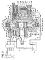
- a common rail type fuel injection system (a pressure accumulation type fuel injection system) including a fuel injection pump 4 according to a first embodiment of the present invention is illustrated.
- the common rail type fuel injection system shown in Fig. 1 is used in an internal combustion engine such as a multicylinder (four-cylinder, in Fig. 1 ) diesel engine.
- the fuel injection system accumulates high-pressure fuel in a common rail 1 and injects the accumulated high-pressure fuel into combustion chambers of respective cylinders of the engine through multiple injectors (electromagnetic fuel injection valves) 2 mounted in accordance with the respective cylinders of the engine.
- injectors electromagagnetic fuel injection valves
- the common rail type fuel injection system includes the common rail 1, the multiple injectors 2, the fuel injection pump (the supply pump) 4 and a control device (an electronic control unit, or an ECU) as controlling means.
- the common rail 1 accumulates the high-pressure fuel.
- the injectors 2 are mounted on the respective cylinders of the engine and inject the high-pressure fuel accumulated in the common rail 1 into the combustion chambers of the respective cylinders.
- the supply pump 4 pressurizes the fuel and supplies the fuel toward the common rail 1.
- the ECU controls a valve opening operation and a valve closing operation of the multiple injectors 2 (more specifically, electromagnetic valves 3) and the supply pump 4 (more specifically, a suction quantity control electromagnetic valve 5), for instance.
- the high-pressure fuel is pressure-fed from the supply pump 4 into the common rail 1 through a high-pressure fuel pipe 6.
- a fuel pressure sensor and a pressure limiter 7 are mounted to the common rail 1.
- the fuel pressure sensor senses the fuel pressure in the common rail 1 (a common rail pressure). If the common rail pressure exceeds a limit set pressure, the pressure limiter 7 opens in order to limit the common rail pressure below the limit set pressure.
- the fuel injection from the injector 2 into the combustion chamber is controlled by energizing and deenergizing the electromagnetic valve 3.
- the electromagnetic valve 3 controls the fuel pressure in a back pressure control chamber, which drives a command piston moving with a nozzle needle. More specifically, while the electromagnetic valve 3 of the injector 2 is energized and the nozzle needle is opened, the high-pressure fuel accumulated in the common rail 1 is supplied into the combustion chamber of each cylinder through the injection. Thus, the engine is operated.
- the supply pump 4 includes a camshaft 11 as a pump drive shaft, a cam 44 rotating with the camshaft 11, a cam ring 45 revolving around the camshaft 11 along an outer periphery of the cam 44, first and second plungers 41, 42, a rotary pump 12, the suction quantity control electromagnetic valve 5 as a control valve, check valves 31, 32 as first and second suction valves 31, 32, discharge valves 61 and a housing 30, in which the above components are housed or mounted.
- the camshaft 11 as the pump drive shaft rotated by the engine is rotatably held in the housing 30.
- a drive pulley is attached to an outer periphery of a tip end (the left end in Fig. 1 ) of the camshaft 11.
- the drive pulley is linked with a crank pulley of a crankshaft of the engine through a driving force transmitting member such as a belt and is driven.
- a rotary pump (a feed pump) 12 for supplying the low-pressure fuel is connected to the other tip end (the right end in Fig.1 ) of the camshaft 11.
- the feed pump 12 rotates integrally with the camshaft 11 and draws the fuel from the fuel tank 9 through a fuel supply passage 10.
- the feed pump 12 is illustrated in a state in which the feed pump 12 is rotated by an angle of 90°.
- the feed pump 12 may have any type of pump structure such as a vane type pump structure, instead of the inner gear type pump structure shown in Fig. 1 .
- the inner gear type pump 12 includes an inner rotor 12a, which is fitted to the camshaft 11 with a clearance, and an outer rotor 12b, which is driven by the inner rotor 12a in sun-and-planet motion.
- a fuel filter 13 is disposed in the fuel supply passage 10.
- the fuel filter 13 filters or traps impurities in the fuel drawn from the fuel tank 9 into the feed pump 12.
- an inlet (a fuel inlet portion) 14 and a fuel introduction passage 15 are formed on a suction side of the feed pump 12.
- the inlet 14 includes a sleeve nipple and a screw and introduces the fuel into the housing 30 from the outside.
- the fuel introduction passage 15 connects the inlet 14 with the feed pump 12.
- the inlet 14 incorporates a filter (a suction portion filter) 14a as shown in Fig. 1 .
- a discharge side of the feed pump 12 is connected with the suction quantity control electromagnetic valve 5 (more specifically, a fuel sump chamber 17a on the tip end side of the suction quantity control electromagnetic valve 5) through a fuel leading passage 16a.
- the fuel sump chamber 17a is a space provided by an accommodation hole 17 of the suction quantity control electromagnetic valve 5 formed in the housing 30 and the tip end portion (the left end in Fig. 1 ) of the suction quantity control electromagnetic valve 5 accommodated in the accommodation hole 17.
- the accommodation hole 17 is a stepped hole having a bottom.
- the accommodation hole 17 is provided by a hole portion with the bottom having substantially the same internal diameter as a valve housing 21 explained after, and a control fuel storage portion, whose internal diameter is larger than the hole portion.
- a space defined by the valve housing 21 and the control fuel storage portion provides a control fuel (low-pressure fuel) storage chamber 17b.
- a mesh size of the suction portion filter 14a of the inlet 14 should be preferably smaller than that of the fuel filter 13.
- the fuel introduction passage 15 is formed with a suction hole 14b on the inlet 14 side.
- the inlet 14 can be connected to the suction hole 14b through screwing and the like.
- the inlet 14 and the fuel introduction passage 15 (more specifically, the suction hole 14b) provide a suction portion for introducing the fuel from the outside.
- the suction portion filter 14a is incorporated by the inlet 14.
- the suction portion filter 14a may be disposed in the suction hole 14b or in the fuel introduction passage 15 if the suction portion filter 14a is disposed inside the suction portion, which introduces the fuel from the outside.
- a pressure regulation valve (a regulation valve) 18 is disposed near the feed pump 12 as shown in Fig. 1 .
- the regulation valve 18 prevents the discharging pressure of the low-pressure fuel discharged from the feed pump 12 into the fuel sump chamber 17a of the suction quantity control electromagnetic valve 5 from exceeding a predetermined fuel pressure.
- the suction quantity control electromagnetic valve 5 is a normally-open type electromagnetic flow control valve as shown in Fig. 1 .
- the suction quantity control electromagnetic valve 5 has a valve member (a valve) 22, which is slidably held inside a sleeve-shaped valve housing 21, an electromagnetic driving portion 23 as valve driving means for deriving the valve 22 in a valve closing direction, and a coil spring 24 as valve biasing means for biasing the valve 22 in a valve opening direction.
- the electromagnetic driving portion 23 When energized, the electromagnetic driving portion 23 generates an electromagnetic force and attracts a movable member (an armature) 26, which moves with the valve 22.
- the valve 22 is opened by the biasing force of the coil spring 24 when the electromagnetic driving portion 23 is de-energized. If the electromagnetic driving portion 23 is energized, the valve 22 opens against the biasing force of the coil spring 24.
- the valve 22 and the valve housing 21 provide a valve portion for performing valve opening operation and valve closing operation.
- the suction quantity control electromagnetic valve 5 may be any type of electromagnetic valve if the suction quantity control electromagnetic valve 5 has the valve portion 21, 22 for streaming or blocking the control fuel, and the electromagnetic driving portion 23 for driving the valve portion 21, 22 to perform the valve opening operation and the valve closing operation.
- the clearance between the valve 22 and the valve housing 21 and an armature chamber accommodating the armature 26 of the electromagnetic driving portion 23 should be preferably formed so that the fuel flows through the clearance and the armature chamber without staying there.
- surplus fuel which is generated when the suction quantity control electromagnetic valve 5 controls the flow of the fuel, is returned to the suction side of the feed pump 12 through a fuel return passage 12h connected to the suction quantity control electromagnetic valve 5, and the fuel introduction passage 15.
- Part of the fuel discharged from the feed pump 12 is introduced into the cam chamber 5 through a fuel lubrication passage 12r connected to the feed pump 12 and lubricates various sliding portions such as the plungers 41, 42.
- the fuel flows out of the supply pump 4 through an outlet (a fuel outlet portion) 19, which is provided by a sleeve nipple and a screw.
- the fuel flowing out of the outlet 19 is returned to the fuel tank 9 through the fuel return passage 8.
- the fuel return passage 12h and the fuel introduction passage 15 constitute a fuel suction passage for introducing the fuel into the feed pump 12.
- the fuel lubrication passage 12r and the cam chamber 50 constitute a return fuel passage for lubricating the various sliding portions of the various operating members and for returning the surplus fuel.
- the control fuel (the low-pressure fuel) controlled by the suction quantity control electromagnetic valve 5 flows out to the control fuel storage chamber 17b.
- the low-pressure fuel is drawn into multiple fuel pressurizing chambers 51, 52 through multiple (two, in Fig. 1 ) control fuel passages 16b and the multiple suction valves 31, 32. More specifically, the control fuel storage chamber 17b communicates with the control fuel passage 16b and the fuel suction passage 20 in that order.
- the fuel suction passage 20 communicates with one of the suction valves 31, 32.
- the fuel pressurizing chambers 51, 52 are spaces defined by the plungers 41, 42 and the suction valves 31, 32 for storing the fuel.
- the number of the control fuel passages 16b or the fuel suction passages 20 is set in accordance with the number of the fuel pressurizing chambers 51, 52 (more specifically, the number of the plungers 41, 42).
- the first suction valve 31 and the first fuel pressurizing chamber 51 correspond to the first plunger 41.
- the second suction valve 32 and the second fuel pressurizing chamber 52 correspond to the second plunger 42.
- the fuel leading passage 16a, the fuel sump chamber 17a, the control fuel storage chamber 17b, the control fuel passage 16b and the fuel suction passage 20 constitute the low-pressure fuel passage.
- the suction quantity control electromagnetic valve 5 is disposed in the low-pressure fuel passage.
- the first suction valve 31 is a check valve, whose forward direction coincides with the flow direction of the fuel flowing from the feed pump 12 toward the first fuel pressurizing chamber 51.
- the first suction valve 31 includes a valve member 31a and a coil spring 31c as biasing means for biasing the valve member 31a in a direction for seating the valve member 31a on a valve seat 31b.
- the first suction valve 31 functions as a check valve for preventing backflow of the fuel from the first fuel pressurizing chamber 51 toward the suction quantity control electromagnetic valve 5.
- the first valve member 31a is biased by the biasing force of the coil spring 31c upward in Fig. 1 and is seated on the valve seat 31b.
- the first suction valve 31 is closed.
- the fuel pressure of the low-pressure fuel opens the first valve member 31a and the fuel is drawn into the first fuel pressurizing chamber 51. If the first plunger 41 moves and pressurizes the fuel in the first fuel pressurizing chamber 51, the valve member 31a of the first suction valve 31 is closed by the fuel pressure in the first fuel pressurizing chamber 51, and the state is retained until the_pressure-feeding of the fuel is finished.
- the second suction valve 32 is a check valve, whose forward direction coincides with the flow direction of the fuel flowing from the feed pump 12 toward the second fuel pressurizing chamber 52.
- the second suction valve 32 includes a valve member 32a and a coil spring 32c as biasing means for biasing the valve member 32a in a direction for seating the valve member 32a on a valve seat 32b.
- the second suction valve 32 functions as a check valve for preventing backflow of the fuel from the second fuel pressurizing chamber 52 toward the suction quantity control electromagnetic valve 5.
- the valve member 32a is biased by the biasing force of the coil spring 32c downward in Fig. 1 and is seated on the valve seat 32b.
- the fuel pressure of the low-pressure fuel opens the valve member 32a and the fuel is drawn into the second fuel pressurizing chamber 52. If the second plunger 42 moves and pressurizes the fuel in the second fuel pressurizing chamber 52, the valve member 32a of the second suction valve 32 is closed by the fuel pressure in the second fuel pressurizing chamber 52, and the state is retained until the pressure-feeding of the fuel is finished.
- the first suction valve 31 is disposed short of the first fuel pressurizing chamber 51 in the low-pressure fuel passage. More specifically, the first suction valve 31 is disposed at a point where the first suction valve 31 and the first plunger 41 define the first fuel pressurizing chamber 51. Instead, the first suction valve 31 may be disposed in the fuel suction passage 20 connected to the first fuel pressurizing chamber 51.
- the second suction valve 32 is disposed short of the second fuel pressurizing chamber 52 in the low-pressure fuel passage. More specifically, the second suction valve 32 is disposed at a point where the second suction valve 32 and the second plunger 42 define the second fuel pressurizing chamber 52. Instead, the second suction valve 32 may be disposed in the fuel suction passage 20 connected to the second fuel pressurizing chamber 52.
- the cam (the eccentric cam) 44 is integrally formed on an outer periphery of an intermediate portion of the camshaft 11.
- the two plungers 41, 42 are disposed at substantially symmetric positions across the eccentric cam 44 along the vertical direction in Fig. 1 .
- the eccentric cam 44 is disposed eccentrically with respect to the axial center of the camshaft 11 and has a substantially circular section.
- a cam ring 45 having a substantially rectangular profile is slidably held on the outer periphery of the eccentric cam 44 through a ring-shaped bush 43.
- a hollow portion having a substantially circular section is formed in the cam ring 45.
- the bush 43 and the eccentric cam 44 are housed inside the hollow portion.
- Plate members 46, 47 respectively integrated with the two plungers 41, 42 are disposed respectively on the upper end surface and the lower end surface of the cam ring 45 in Fig. 1 .
- the plate members 46, 47 are pressed against the upper end surface and the lower end surface of the cam ring 45 in Fig. 1 by biasing forces of coil springs 48, 49, which are disposed around the outer peripheries of the plungers 41, 42 respectively.
- the eccentric cam 44 and the cam ring 45 are made of metallic material and are rotatably housed inside the cam chamber 50 formed in the housing 30.
- the plungers 41, 42 are housed in sliding holes of the housing 30 (more specifically, sliding holes 33a, 34a of second housing portions 33, 34) respectively so that the plungers 41, 42 can reciprocate in a sliding manner.
- the first fuel pressurizing chamber 51 is provided by an inner peripheral surface of the sliding hole 33a and the first suction valve 31 (more specifically, the valve member 31a) on the upper end surface of the first plunger 41 in Fig. 1 .
- the second fuel pressurizing chamber 52 is provided by an inner peripheral surface of the sliding hole 34a and the second suction valve 32 (more specifically, the valve member 32a) on the lower end surface of the second plunger 42 in Fig. 1 .
- the first discharge valve 61 is connected with the first fuel pressurizing chamber 51 through a first fuel pressure-feeding passage 35.
- the second discharge valve is connected with the second fuel pressurizing chamber 52 through a second fuel pressure-feeding passage.
- the first discharge valve 61 and the second discharge valve function as check valves for preventing backflow of the high-pressure fuel from a first discharge hole 63 and a second discharge hole toward the first fuel pressurizing chamber 51 and the second fuel pressurizing chamber 52 respectively.
- the first discharge valve 61 and the second discharge valve include ball valves 35 and coil springs 62 respectively.
- the high-pressure fuel discharged from the first discharge hole 63 and the second discharge hole flows into a high-pressure fuel pipe 6 through a fuel pressure-feeding passage 67 inside a first pipe connector (a delivery valve holder) 65 and a fuel pressure-feeding passage inside a second delivery valve holder, and is supplied into the common rail 1.
- the fuel pressure-feeding passage 35, the first discharge hole 63 and the fuel pressure-feeding passage 67 constitute a high-pressure fuel pressure-feeding passage.
- the first discharge valve 61 is disposed in the high-pressure fuel pressure-feeding passage.
- the first discharge valve 61 and the delivery valve holder 65 constitute a discharge portion for discharging the fuel to the outside (more specifically, to the common rail 1 and the like through the high-pressure fuel pipe 6).
- the inlet portion 14, 14b, 15, the low-pressure fuel passage 16a, 17a, 17b, 16b, 20 and the high-pressure fuel pressure-feeding passage 35, 63, 67 provide a fuel passage leading from the suction portion 14, 14b, 15 (more specifically, the suction portion filter 14a) to the discharge portion 61, 65 through the fuel pressurizing chamber 51.
- a passage leading from the feed pump 12 (more specifically, the discharge side of the feed pump 12) to the discharge portion 61, 65 through the fuel pressurizing chamber 51 provides a fuel passage portion.
- the housing 30 is made of metallic material and has a first housing portion 30a and the second housing portions 33, 34.
- the first housing portion 30a rotatably houses the camshaft 11, the cam ring 45 and the feed pump 12.
- the second housing portions 33, 34 house the first and second plungers 41, 42 respectively so that the plungers 41, 42 can reciprocate in a sliding manner.
- the camshaft 11 is rotatably housed in the first housing portion 30a through a bearing so that the tip end (the left end in Fig. 1 ) of the camshaft 11 is inserted through the first housing portion 30a.
- the first housing portion 30a is formed with the fuel leading passage 16a, the fuel sump chamber 17a, the control fuel storage chamber 17b and the control fuel passage 16b of the low-pressure fuel passage formed in the housing 30.
- the first housing portion 30a is formed with the fuel lubrication passage 12r out of the fuel suction passage 12h, 15 and the return fuel passage 12r, 50.
- the fuel leading passage 16a, the fuel sump chamber 17a, the control fuel storage chamber 17b and the control fuel passage 16b constitute a first low-pressure fuel passage.
- the suction quantity control electromagnetic valve 5 is disposed in the first low-pressure fuel passage.
- the first housing portion 30a is divided into a bearing housing portion (a bearing portion) 30b for rotatably bearing the camshaft 11, and a main body portion 30c for rotatably housing the feed pump 12.
- the bearing portion 30b and the main body portion 30c are integrated with each other after the camshaft 11 is inserted through the bearing portion 30b and the main body portion 30c.
- the first housing portion 30a may be formed in a single piece.
- the main body portion 30c is formed with the first low-pressure fuel passage 16a, 17a, 17b, 16b, the fuel suction passage 12h, 15 and the fuel lubrication passage 12r.
- the suction quantity control electromagnetic valve 5, the inlet 14 and the outlet 19 can be attached to the main body portion 30c.
- the two second housing portions 33, 34 are fluid-tightly fixed to the upper and lower end surfaces of the first housing portion 30a in Fig. 1 .
- the second housing portions 33, 34 and the first housing portion 30a define the cam chamber 50.
- the cam chamber 50 houses the sliding members such as the eccentric cam 44 and the cam ring 45, the plungers 41, 42 and the coil springs 48, 49 for pressing the plate members 46, 47 against the cam ring 45.
- Two thrust washers 71 are interposed between ring-shaped inner wall surfaces of the cam chamber 50 and both end surfaces of the eccentric cam 44 along the thrust direction (the axial direction).
- the eccentric cam 44, the bush 43, the cam ring 45 and the plate members 46, 47 can rotate or reciprocate easily.
- Each washer 71 has an external diameter corresponding to the area of the revolution of the cam ring 45.
- the washers 71 should be preferably fixed to both end surfaces of the cam chamber 50 in the thrust direction.
- the second housing portions 33, 34 are formed with the sliding holes 33a, 34a respectively.
- the plungers 41, 42 are housed respectively inside the sliding holes 33a, 34a so that the plungers 41, 42 can reciprocate in the sliding manner.
- the second housing portions 33, 34 are formed with the fuel pressurizing chambers 51, 52, which are provided by the end surfaces of the plungers 41, 42, the inner peripheral surfaces of the sliding holes 33a, 34a and the suction valves 31, 32 (more specifically, the valve members 31a, 32a) respectively.
- the second housing portions 33, 34 are formed with the fuel suction passages 20 of the low-pressure fuel passage formed in the housing 30.
- the second housing portions 33, 34 are formed with accommodation holes 37, 38 for accommodating the suction valves 31, 32, and the fuel suction passages 20 are connected to the accommodation holes 37, 38.
- the second housing portions 33, 34 are formed with the high-pressure fuel pressure-feeding passages 35, 63, 67.
- the discharge valve 61 and the delivery valve holder 65 are disposed in the high-pressure fuel pressure-feeding passage 35, 63, 67.
- the fuel suction passage 20 provides a second low-pressure fuel passage.
- the second housing portions 33, 34 and the plungers 41, 42 constitute pump elements (high-pressure supply pumps) of the supply pump 4 respectively.
- the second housing portions 33, 34 constituting the pump elements are cylinder heads.
- the second housing portions 33, 34 are made of metallic material having mechanical strength such as abrasion resistance and seizing resistance.
- the first housing portion 30a except the bearing for rotatably holding the camshaft 11 is made of aluminum such as die-cast aluminum or aluminum alloy.
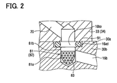
- filters 81, 82 are disposed at the outlet portions of the first low-pressure fuel passage 16a, 17a, 17b, 16b formed in the first housing portion 30a (more specifically, the main body portion 30c). More specifically, the filters 81, 82 are disposed on outlet 16bo sides of the control fuel passages 16b formed in the first housing portion 30a (more specifically, the main body portion 30c). The filters 81, 82 are fixed into holes (fitting holes) 83 of the control fuel passages 16b formed on the upper and lower end surfaces of the first housing portion 30a in Fig. 1 through fitting fixation and the like. As shown in Fig.
- the filters 81, 82 respectively include metallic mesh portions 81a, 82a made of stainless steel metallic meshes or the like, and guide portions 81b, 82b for holding the metallic mesh portions 81a, 82a.
- the metallic mesh portions 81a, 82a are formed substantially in the shape of cones and trap extraneous matters.
- the external diameters of the guide portions 81b, 82b are set so that the guide portions 81b, 82b can be fitted into the fitting holes 83.
- the filters 81, 82 are inserted and fixed so that the tip ends of the substantially conical shapes of the metallic mesh portions 81a, 82a are directed upstream with respect to the flow of the fuel.
- the filters 81, 82 should be preferably mounted so that the filters 81, 82 do not protrude from the upper end surface and the lower end surface of the first housing portion 30a (more specifically, the main body portion 30c) in Fig. 1 .
- each one of the filters 81, 82 should be preferably set at a small size in a mesh range, in which the fuel supply quantity (the fuel pressure-feeding quantity) of the fuel supplied from the suction quantity control electromagnetic valve 5 to the fuel pressurizing chambers 51, 52 is not restricted below an appropriate quantity.
- Stepped portions 16ad continuing to the fitting holes 83 are formed on the upper end surface and the lower end surface of the first housing portion 30a in Fig. 1 , and sealing members 91 such as O rings are disposed on the stepped portions 16ad as shown in Fig. 2 so that the first housing portion 30a and the second housing portions 33, 34 can hold the fluid-tightness.
- the feed pump 12 is driven by the rotational movement of the camshaft 11. If the feed pump 12 starts the drive, the fuel in the fuel tank 9 is introduced into the fuel introduction passage 15 through the fuel supply passage 10, the fuel filter 13 and the inlet 14, and is drawn into the suction side of the feed pump 12.
- the feed pump 12 pressurizes the drawn fuel to a predetermined pressure and discharges the low-pressure fuel into the fuel sump chamber 17a of the suction quantity control electromagnetic valve 5 through the fuel leading passage 16a.
- the cam ring 45 revolves along a predetermined substantially circular passage of the cam 44.
- the plate members 46, 47 reciprocate on the upper and lower end surfaces of the cam ring 45 in Fig. 1 .
- the first and second plungers 41, 42 reciprocate inside the sliding holes 33a, 34a in the vertical direction in Fig. 1 .
- the first and second plungers 41, 42 pressurize the fuel in the first and second pressurizing chambers 51, 52 and pressure-feed the high-pressure fuel. More specifically, if the first plunger 41 moves from a top dead center to a bottom dead center in the sliding hole 33a in a suction stroke, the low-pressure fuel discharged from the feed pump 12 opens the first suction valve 31 and flows into the first fuel pressurizing chamber 51.
- the first plunger 41 having reached the bottom dead center moves toward the top dead center in the sliding hole 33a in a pressure-feeding stroke, and the fuel pressure in the first fuel pressurizing chamber 51 is increased in accordance with the increase in the lifting degree of the first plunger 41.
- the second plunger 42 moves from a top dead center to a bottom dead center in the sliding hole 34a in a suction stroke, the low-pressure fuel discharged from the feed pump 12 opens the second suction valve 32 and flows into the second fuel pressurizing chamber 52.
- the second plunger 42 having reached the bottom dead center moves toward the top dead center in the sliding hole 34a in a pressure-feeding stroke, and the fuel pressure in the second fuel pressurizing chamber 52 is increased in accordance with the increase in the lifting degree of the second plunger 42.
- the discharge valve 61 is opened by the increased fuel pressure, the high-pressure fuel pressurized in the fuel pressurizing chamber 51 flows out of the fuel pressure-feeding passage 67 in the delivery valve holder 65 through the fuel pressure-feeding passage 35 and the discharge hole 63. Then, the high-pressure fuel flowing out of the fuel pressure-feeding passage 67 is pressure-fed into the common rail 1 through the high-pressure fuel pipe 6.
- the eccentric cam 44 is eccentric with respect to the camshaft 11. Therefore, as shown in Fig. 1 , the first plunger 41 and the second plunger 42 reciprocate alternately.
- the first plunger 41 is in a state of a maximum cam lift (a maximum plunger lift), or in an upper dead center state, after moving upward.
- the second plunger 42 is in a state of a minimum cam lift (a minimum plunger lift), or in a bottom dead center state, after moving upward in Fig. 1 .
- the housing 30 includes the first housing portion 30a for rotatably housing the feed pump 12, and the second housing portions 33, 34 for housing the plungers 41, 42 so that the plungers 41, 42 can reciprocate.
- the housing 30 is made up of the separate components. Therefore, the filters 81, 82 can be easily mounted.
- the first low-pressure fuel passage 16a, 17a, 17b, 16b is formed in the first housing portion 30a for providing the passages for streaming the low-pressure fuel from the feed pump 12 toward the fuel pressurizing chambers 51, 52.
- Each one of the filters 81, 82 is disposed in the outlet portion of the first low-pressure fuel passage 16a, 17a, 17b, 16b, or on the outlet 16bo side of the control fuel passage 16b. Therefore, even if the extraneous matters remain in the first low-pressure fuel passage 16a, 17a, 17b, 16b of the housing 30 (more specifically, the first housing portion 30a) because of insufficient cleaning in high-pressure cleaning, the extraneous matters are trapped with the filters 81, 82. Therefore, the extraneous matters, which can enter the fuel pressurizing chambers 51, 52, are eliminated.
- the suction valves 31, 32 are disposed short of the fuel pressurizing chambers 51, 52 in the second low-pressure fuel passages (the fuel suction passages) 20 communicating with the fuel pressurizing chambers 51, 52 in the second housing portions 33, 34.
- the suction valves 31, 32 are disposed downstream of the filters 81, 82 with respect to the flow of the fuel. Therefore, the extraneous matters, which can enter the suction valves 31, 32, are eliminated by the filters 81, 82. Accordingly, the troubles due to the extraneous matters, which will degrade performance and reliability of the suction valves 31, 32, can be prevented.
- the suction quantity control electromagnetic valve 5 is disposed in the first low-pressure fuel passage 16a, 17a, 17b, 16b of the first housing portion 30a.
- the suction quantity control electromagnetic valve 5 controls the quantity of the fuel flowing through the suction valves 31, 32, or the suction quantity of the fuel drawn into the fuel pressurizing chambers 51, 52 corresponding to the pressure-feeding quantity (the discharging quantity) of the fuel. Therefore, the first low-pressure fuel passage 16a, 17a, 17b, 16b formed inside the first housing portion 30a is prone to be complicated.
- Each one of the fuel pressurizing chambers 51, 52 communicates with the high-pressure fuel pressure-feeding passage 35, 63, 67 for discharging the high-pressure fuel toward the common rail 1.
- Each one of the discharge valves 61 is disposed in the high-pressure fuel pressure-feeding passage 35, 63, 67.
- the housing 30 has the suction portion filter 14a in the suction portion 14, 14b, 15 for introducing the fuel from the outside.
- the housing 30 is formed with the fuel passage leading from the suction portion filter 14a to the discharge portions 61, 65 through the fuel pressurizing chambers 51, 52 for discharging the fuel.
- the filters 81, 82 may be disposed in the above fuel passage.
- the filters 81, 82 should be preferably disposed in the fuel passage portion leading from the feed pump 12 disposed downstream of the suction portion filter 14a to the discharge portion 61, 65 through the fuel pressurizing chamber 51, 52 in the fuel passage.
- the extraneous matters which can enter the suction valves 31, 32 or the discharge valves 61 of the discharge portions 61, 65, are trapped with the filters 81, 82.
- the filters 81, 82 are disposed in the second low-pressure fuel passages (the fuel suction passages) 20 as shown in Fig. 3 , instead of disposing the filters 81, 82 on the sides of the outlets 16bo of the first low-pressure fuel passage 16a, 17a, 17b, 16b as in the first embodiment.
- the second housing portions 33, 34 are formed with the accommodation holes 37, 38 for accommodating the suction valves 31, 32.
- the filters 81, 82 are fixed to the openings of the second low-pressure fuel passages 20 communicating with the accommodation holes 37, 38 through fitting fixation and the like.
- An effect similar to the effect of the first embodiment can be obtained by disposing the filters 81, 82 in the second low-pressure fuel passages 20 downstream of the first low-pressure fuel passage 16a, 17a, 17b, 16b in the low-pressure fuel passage 16a, 17a, 17b, 16b, 20, through which the low-pressure fuel flows from the feed pump 12 toward the pressurizing chambers 51, 52.
- each one of the filters 81, 82 is disposed in one of both openings of the second low-pressure fuel passage 20 on the side connected to each one of the accommodation holes 37, 38. More specifically, the filters 81, 82 are disposed in the outlets of the second housing portions 33, 34 with respect to the flow of the fuel. Thus, manufacturing and assembly for mounting the filters 81, 82 to the second housing portions 33, 34 can be facilitated.
- the filters 81, 82 may be disposed in the other openings of the second low-pressure fuel passages 20 facing the outlet portions 16bo. More specifically, the filters 81, 82 may be disposed in the inlets of the second low-pressure fuel passages 20 with respect to the flow of the fuel. Also in this case, the manufacturing and the assembly for mounting the filters 81, 82 to the second housing portions 33, 34 can be facilitated.
- the fuel flow passage of the second low-pressure fuel passage 20 is formed relatively simply, compared to the first low-pressure fuel passage 16a, 17a, 17b, 16b. Therefore, there is little or no possibility that the extraneous matters remaining because of the insufficient cleaning in the high-pressure cleaning of the second housing portions 33, 34 stay in the second low-pressure fuel passages 20. Therefore, an effect similar to the effect of the first embodiment can be obtained even if the filters 81, 82 are disposed in the inlet portions of the second low-pressure fuel passages 20 facing the outlet portions 16bo or in the openings (the outlet portions) on the sides communicating with the accommodation holes 37, 38.
- the housing 30 includes the first housing portion 30a and the second housing portions 33, 34, so the housing 30 is made up of the separate components.
- the first housing portion 30a rotatably houses the camshaft 11, the cam ring 45 and the feed pump 12.
- the second housing portions 33, 34 house the plungers 41, 42 in the sliding holes 33a, 34a so that the plungers 41, 42 can reciprocate.
- each one of the filters 81, 82 is disposed in one of the outlet portion of the first low-pressure fuel passage 16a, 17a, 17b, 16b formed in the first housing portion 30a, the inlet portion of the second low-pressure fuel passage 20 facing the outlet portion of the first low-pressure fuel passage, and the second low-pressure fuel passage 20 leading from the inlet portion to each one of the pressurizing chambers 51, 52. Therefore, even if the extraneous matters remain in the first low-pressure fuel passage 16a, 17a, 17b, 16b because of the insufficient cleaning in the high-pressure cleaning, the extraneous matters can be trapped with the filters 81, 82. Therefore, the troubles, which are caused by the extraneous matters and degrade the performance and the reliability of the suction valves 31, 32, the plungers 41, 42 and the discharge valve 61, can be prevented.
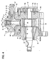
- the filter 81 is interposed between the bearing portion 30b and the main body portion 30c, which construct the first housing portion 30a so that the first housing portion 30a is made up of the separate components, as shown in Fig. 4 .
- the first low-pressure fuel passage, the fuel suction passage and the fuel lubrication passage formed in the main body portion 30c are not shown in Fig. 4 .
- the inlet 14 and the suction quantity control electromagnetic valve 5 are not shown in Fig. 4 .
- the fuel injection pump shown in Fig. 4 has three plungers 41, or three pump elements.
- the three plungers 41 are disposed around the camshaft 11 at an angular interval of 120°. Only one of the three plungers 41 is shown in Fig. 4 .
- the profile of the section of the cam ring 45 perpendicular to the axis is formed in the shape of a particular hexagon, which is made up of three straight lines and three arcs. More specifically, the outer peripheral surface of the cam ring 45 is made up of three flat surfaces and three curved surfaces.
- the three plungers 41 are pressed against the three flat surfaces of the cam ring 45 by the coil springs 48 through the plate members 46 respectively.
- the main body portion 30c is formed with a control fuel passage 16f and a first fuel passage portion (a first low-pressure fuel passage portion) of the first low-pressure fuel passage communicating with the second low-pressure fuel passage (the fuel suction passage) 20.
- the control fuel passage 16f has an opening facing a groove 16e of the bearing portion 30b and the other opening facing the inlet portion of the second low-pressure fuel passage 20.
- the first fuel passage portion leads from the feed pump 12 to the groove 16e.
- the groove 16e is a part of the first fuel passage portion.
- the groove 16e is formed on the outer periphery of the bearing portion 30b so that the groove 16e extends circumferentially and the control fuel passages 16f corresponding to the three plungers 41 are connected to the groove 16e.
- the filter 81 is disposed in one of both openings of the control fuel passage 16f formed in the main body portion 30c. In Fig. 4 , the filter 81 is disposed in the opening of the control fuel passage 16f facing the groove 16e.
- the filter 81 is disposed in the opening portion, or the outlet portion, of the control fuel passage 16f formed in the first housing 30a (more specifically, the main body portion 30c) like the first embodiment. Therefore, an effect similar to the effect of the first embodiment can be obtained.
- the filter 81 may be disposed in the opening portion (the outlet portion) of the control fuel passage 16f on the side communicating with the second low-pressure fuel passage (the fuel suction passage) 20.
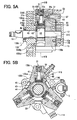
- a housing main body portion 130c of a housing 130 houses the plungers 41 so that the plungers 41 can reciprocate and houses the eccentric cam 44 and the cam ring 45 so that the eccentric cam 44 and the cam ring 45 can rotate.
- the housing 130 includes a bearing portion 130b and the housing main body portion 130c.
- the bearing portion 130b rotatably houses one of both ends (the left end in Fig. 5A ) of the camshaft 11.
- the housing main body portion 130c rotatably houses the eccentric cam 44 and the cam ring 45 in the cam chamber 50.
- the housing main body portion 130c houses the plunger 41 in a sliding hole 130ca so that the plunger 41 can reciprocate in a vertical direction in Fig. 5A .
- the fuel pressurizing chamber 51 is provided by an inner peripheral surface of the sliding hole 130ca and the suction valve 31 (more specifically, the valve member 31a) on the upper end surface of the plunger 41 in Fig. 5A .
- the suction valve 31 and the discharge valve 61 communicating with the fuel pressurizing chamber 51 through the fuel pressure-feeding passage 35 are disposed in the housing main body portion 130c.
- the housing main body portion 130c is formed with a fuel suction passage 420, which communicates with the suction valve 31.
- the bearing portion 130b is formed with a concave stepped portion 130bj and the housing main body portion 130c is formed with a convex stepped portion 130cj.
- the convex stepped portion 130cj can be inserted into the concave stepped portion 130bj.
- the concave stepped portion 130bj and the convex stepped portion 130cj are formed substantially in the shape of rings and provide a ring-shaped fuel passage 316e extending circumferentially.
- the bearing portion 130b is formed with a control fuel passage 316f for connecting the ring-shaped fuel passage 316e with the fuel suction passage 420. The fuel flows from the discharge portion of the feed pump 12 to the ring-shaped fuel passage 316e through a third low-pressure fuel passage 516.
- the ring-shaped fuel passage 316e and the control fuel passage 316f provide a first low-pressure fuel passage in the bearing portion 130b for streaming the low-pressure fuel.
- the outlet portion of the first low-pressure fuel passage 316e, 316f of the bearing portion 130b on the fuel pressurizing chamber 51 side faces the inlet portion of the fuel suction passage 420.
- the low-pressure fuel is introduced from the outlet portion of the first low-pressure fuel passage 316e, 316f to the inlet portion of the fuel suction passage 420.
- the fuel suction passage 420 is formed in the housing main body portion 130c and provides a second low-pressure fuel passage leading toward the pressurizing chamber 51.
- the filter 81 is disposed in the inlet portion of the second low-pressure fuel passage (the fuel suction passage) 420 as shown in Fig. 5A .
- an inlet 114 and the suction quantity control electromagnetic valve 5 may be disposed in the bearing portion 130b.
- An outlet 119 may be disposed in the housing main body portion 130c.
- a cylindrical cup member 146 with a bottom is interposed between the plate member 46 and the cam ring 45.
- the cup member 146 may not be interposed between the plate member 46 and the cam ring 45.
- the housing 130 includes the bearing portion 130b, which rotatably houses the camshaft 11, and the housing main body portion 130c, which is coupled with the bearing portion 130b through insertion.
- the housing main body portion 130c is an integral-type housing for housing the eccentric cam 44 and the cam ring 45 so that the eccentric cam 44 and the cam ring 45 can rotate and for housing the plunger 41 so that the plunger 41 can reciprocate.
- the filter 81 is disposed in the inlet portion of the second low-pressure fuel passage 420 of the housing main body portion 130c. Therefore, even if the extraneous matters remain in the low-pressure fuel passage of the housing 130 because of the insufficient cleaning in the high-pressure cleaning, the extraneous matters, which can enter the fuel pressurizing chamber 51, are trapped with the filter 81.
- the housing main body portion 130c is formed with the third low-pressure fuel passage 516 for streaming the low-pressure fuel from the feed pump 12 toward the fuel pressurizing chamber 51.
- the outlet portion of the third low-pressure fuel passage 516 on the fuel pressurizing side should be preferably connected to the first low-pressure fuel passage 316e, 316f (the ring-shaped fuel passage 316e, in the present embodiment).
- the low-pressure fuel passage can have a firm structure, compared to the case where the discharge portion of the low-pressure fuel of the feed pump 12 in the housing main body portion 130c is connected with the first low-pressure fuel passage 316e, 316f in the bearing portion 130b through an exterior pipe and the like. Accordingly, the reliability of the low-pressure fuel passage for streaming the low-pressure fuel can be improved.
- the filter 81 may be disposed in a fuel passage leading from the inlet portion of the second low-pressure fuel passage 420 to the fuel pressurizing chamber 51 in the second low-pressure fuel passage 420, instead of disposing the filter 81 in the inlet portion of the second low-pressure fuel passage 420.
- the filter 81 should be preferably disposed in a fuel passage leading from the inlet portion of the second low-pressure fuel passage 420 to the suction valve 31 in the second low-pressure fuel passage 420.
- the filter 81 is disposed upstream of the suction valve 31 with respect to the flow of the fuel. Accordingly, even if the extraneous matters remain in the low-pressure fuel passage of the housing 130, the extraneous matters, which can enter the suction valve 31 and the fuel pressurizing chamber 51, are eliminated. Thus, the troubles, which are caused by the extraneous matters and can degrade the performance and the reliability of the suction valve 31 and the fuel pressurizing chamber 51, can be prevented.
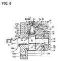
- the filter 81 is disposed in the outlet portion of the first low-pressure fuel passage 316e, 316f of the bearing portion 130b on the fuel pressurizing chamber 51 side as shown in Fig. 6 , instead of disposing the filter 81 in the inlet portion of the second low-pressure fuel passage 420 in the housing main body portion 130c.
- each one of the filters 81, 82 is fitted to the fitting hole 83 formed in the opening portion of the low-pressure fuel passage.
- the guide portion 81b of the filter 81 may be made up of a holding member 81b1 for holding the metallic mesh portion 81a and a sealing portion 81b2 such as a rubber member coated on the upper and lower end surfaces of the holding member 81b1.
- the holding member 81b1 has a flange portion extending outward from the substantial center of the outer periphery.
- the sealing portion 81b2 is formed on the flange portion through burning, insert molding or the like.
- the thickness of the sealing portion 81b2 is set so that the fluid-tightness between the second housing portions 33, 34 and the first housing portion 30a is maintained when the filter 81 is disposed on the stepped portion 16ad. Also in the above structure, an effect similar to the effect of the above embodiments can be obtained. Moreover, since the filter 81 has a function of maintaining the fluid-tightness between the second housing portions 33, 34 and the first housing portion 30a, the sealing member 91 is unnecessary. Thus, the number of the parts can be reduced.
- the metallic mesh portion 81a may be formed substantially in the shape of a cylinder as shown in Fig. 7A , instead of the substantially conical shape.
- the metallic mesh portion 81a may be formed in the shape of a flat plate as shown in Fig. 7B .
- the sealing portion 81b2 shown in Fig. 7B may be coated on the metallic mesh portion 81, or the metallic mesh portion 81 and a sealing member 91 may be disposed separately.
- the metallic mesh portion 81a may be formed of a stainless-steel metallic mesh, or may be formed of porous ceramic material.
- the fuel injection pump according to the first or second embodiment includes the two plungers, and the fuel injection pump according to the third, fourth or fifth embodiment includes the three plungers.
- a similar effect can be obtained by applying the present invention to any type of fuel injection pump having multiple plungers.
- the present invention is applied to the supply pump of the common rail type fuel injection system.
- the present invention can be applied to any type of fuel injection pump if the fuel injection pump has a structure for performing the pressurization of the fuel drawn from the fuel tank, the introduction of the low-pressure fuel (at a pressure between the fuel pressure in the fuel tank and the fuel injection pressure) into the fuel pressurizing chamber, the pressurization of the low-pressure fuel in the fuel pressurizing chamber through the movement of the plunger, and the discharge of the high-pressure fuel (at the fuel pressure corresponding to the fuel injection pressure) through the movement of the plunger.
Landscapes
- Engineering & Computer Science (AREA)
- Chemical & Material Sciences (AREA)
- Combustion & Propulsion (AREA)
- Mechanical Engineering (AREA)
- General Engineering & Computer Science (AREA)
- Fuel-Injection Apparatus (AREA)
- Details Of Reciprocating Pumps (AREA)
- Reciprocating Pumps (AREA)
Claims (7)
- Kraftstoffeinspritzpumpe (4), die folgendes aufweist:eine Nockenwelle (11), die durch eine Brennkraftmaschine angetrieben ist, um sich zu drehen;einen Nocken (44), der sich mit der Nockenwelle (11) dreht;einen Nockenring (45), der sich um die Nockenwelle (11) herum dreht, so dass sich der Nockenring (45) hinsichtlich des Nockens (44) entlang eines Außenumfangs des Nockens (44) dreht;ein Gehäuse (30, 130) zum drehbaren Unterbringen der Nockenwelle (11), wobei das Gehäuse (30, 130) mit einer Kraftstoffdruckbeaufschlagungskammer (51, 52) ausgebildet ist;einen Kolben (41, 42), der sich in Übereinstimmung mit der Umdrehung des Nockenrings (45) hin und her bewegt, um Kraftstoff, der in die Kraftstoffdruckbeaufschlagungskammer (51, 52) gezogen ist, mit Druck zu beaufschlagen und unter Druck zuzuführen, wobeidas Gehäuse (30, 130) einen ersten Filter (14a) an einem Saugabschnitt (14, 14b, 15), der den Kraftstoff von einer Außenseite einleitet, und eine Rotationspumpe (12) aufweist und mit einem Kraftstoffdurchgang (16a, 16b, 16e, 16f, 17a, 17b, 20, 316e, 316f, 420, 516) ausgebildet ist, der von dem ersten Filter (14a) durch die Kraftstoffdruckbeaufschlagungskammer (51, 52) zu einem Abgabeabschnitt (61, 65) führt, der den Kraftstoff abgibt, unddie Rotationspumpe (12) stromabwärtig von dem ersten Filter (14a) zum Zuführen des Kraftstoffs angeordnet ist, der in die Kraftstoffdruckbeaufschlagungskammer (51, 52) gezogen ist, wenn sie durch die Nockenwelle (11) gedreht ist,dadurch gekennzeichnet, dass
die Kraftstoffeinspritzpumpe (4) ferner einen zweiten Filter (81, 82) aufweist, der stromabwärtig von der Rotationspumpe (12) in dem Kraftstoffdurchgang (16a, 16b, 16e, 16f, 17a, 17b, 20, 316e, 316f, 420, 516) angeordnet ist, der in dem Gehäuse (30, 130) stromabwärtig von dem ersten Filter (14a) ausgebildet ist, wobei
das Gehäuse (30, 130) wenigstens zwei Gehäuseabschnitte (30a, 33, 34, 130b, 130c) aufweist, und
der zweite Filter (81, 82) an einer Öffnung des Kraftstoffdurchgangs (16a, 16b, 16e, 16f, 17a, 17b, 20, 316e, 316f, 420, 516) angeordnet ist, der in eine Fläche von einem von dem ersten und dem zweiten Gehäuseabschnitt (30a, 33, 34, 130b, 130c) mündet, an der der erste und der zweite Gehäuseabschnitt (30a, 33, 34, 130b, 130c) aneinander angrenzen, oder an einem bestimmten Punkt in dem Kraftstoffdurchgang (20, 420) in dem zweiten Gehäuseabschnitt (33, 34, 130c). - Kraftstoffeinspritzpumpe (4) nach Anspruch 1, ferner dadurch gekennzeichnet, dass
das Gehäuse (30) einen ersten Gehäuseabschnitt (30a) zum drehbaren Unterbringen der Nockenwelle (11) und des Nockenrings (45) und einen zweiten Gehäuseabschnitt (33, 34) zum Unterbringen des Kolbens (41, 42) aufweist, so dass der Kolben (41, 42) sich hin- und hergehend bewegen kann,
der erste Gehäuseabschnitt (30a) mit einem ersten Niederdruckkraftstoffdurchgang (16a, 16b, 16e, 16f, 17a, 17b) zum Strömen von Niederdruckkraftstoff von der Rotationspumpe (12) zu der Kraftstoffdruckbeaufschlagungskammer (51, 52) ausgebildet ist,
der zweite Gehäuseabschnitt (33, 34) mit einem zweiten Niederdruckkraftstoffdurchgang (20) ausgebildet ist, der mit der Kraftstoffdruckbeaufschlagungskammer (51, 52) verbunden ist. - Kraftstoffeinspritzpumpe (4) nach Anspruch 2, ferner gekennzeichnet durch
ein Absperrventil (31, 32), das in dem zweiten Niederdruckkraftstoffdurchgang (20) des zweiten Gehäuseabschnitts (33, 34) zwischen dem bestimmten Punkt und der Kraftstoffdruckbeaufschlagungskammer (51, 52) angeordnet ist, so dass eine Vorwärtsrichtung des Absperrventils (31, 32) mit einer Strömungsrichtung des Niederdruckkraftstoffs, der zu der Kraftstoffdruckbeaufschlagungskammer (51, 52) strömt, übereinstimmt. - Kraftstoffeinspritzpumpe (4) nach Anspruch 1, ferner dadurch gekennzeichnet, dass
der erste Gehäuseabschnitt (30a) einen Lagerabschnitt (30b) zum drehbaren Unterbringen von einem von beiden Enden der Nockenwellen (11), und einen Hauptkörperabschnitt (30c) aufweist, der an den Lagerabschnitt (30b) angepasst ist,
der Lagerabschnitt (30b) umfänglich an seinem Außenumfang mit einer Nut (16e) ausgebildet ist, und
der Hauptkörperabschnitt (30c) mit einem ersten Kraftstoffdurchgangsabschnitt zum Strömen des Niederdruckkraftstoffs von der Rotationspumpe (12) zu der Nut (16e) in einer Richtung zu der Kraftstoffdruckbeaufschlagungskammer (51, 52), und mit einem zweiten Kraftstoffdurchgangsabschnitt (16f) zum Strömen des Niederdruckkraftstoffs von der Nut (16e) zu dem zweiten Niederdruckkraftstoffdurchgang (20) ausgebildet ist, wobei der erste und der zweite Kraftstoffdurchgangsabschnitt (16e, 16f) wenigstens einen Teil des ersten Niederdruckkraftstoffdurchgangs (16a, 16b, 16e, 16f, 17a, 17b) bilden. - Kraftstoffeinspritzpumpe (4) nach Ansprüchen 1 bis 3, wobei
das Gehäuse (30) einen Lagerabschnitt (130b) zum drehbaren Unterbringen von einem von beiden Enden der Nockenwellen (11) und einen Gehäusehauptkörperabschnitt (130c), der den Lagerabschnitt (130) unterbringt, so dass der Lagerabschnitt (130b) mit dem Gehäusehauptkörperabschnitt (130c) durch ein Einsetzen gekoppelt ist, den Nocken (44), so dass der Nocken (44) sich drehen kann, und den Nockenring (45) aufweist, so dass sich der Nockenring (45) drehen kann. - Kraftstoffeinspritzpumpe (4) nach Anspruch 5, ferner dadurch gekennzeichnet, dass
der Gehäusehauptkörperabschnitt (130c) mit einem dritten Niederdruckkraftstoffdurchgang (516) zum Strömen des Niederdruckkraftstoffs von der Rotationspumpe (12) zu der Kraftstoffdruckbeaufschlagungskammer (51) ausgebildet ist, und
der erste Niederdruckkraftstoffdurchgang (316e, 317f) mit einem Auslassabschnitt des dritten Niederdruckkraftstoffdurchgangs (516) an der Seite der Kraftstoffdruckbeaufschlagungskammer (51) verbunden ist. - Kraftstoffeinspritzpumpe (4) nach Ansprüchen 1 bis 6, ferner gekennzeichnet durch
ein Abgabeventil (61), das zwischen der Kraftstoffdruckbeaufschlagungskammer (51, 52) und einer Common Rail (1) angeordnet ist, zum Strömen von Hochdruckkraftstoff zu der Common Rail (1), falls ein Kraftstoffdruck in der Kraftstoffdruckbeaufschlagungskammer (51, 52) einen Kraftstoffdruck in der Common Rail (1) übersteigt, wobei die Common Rail den Kraftstoff speichert, der in der Kraftstoffdruckbeaufschlagungskammer (51, 52) durch die Bewegung des Kolbens (41, 42) mit Druck beaufschlagt ist, und der durch die Bewegung des Kolbens (41, 42) unter Druck zugeführt ist, bei einem hohen Druck.
Applications Claiming Priority (4)
| Application Number | Priority Date | Filing Date | Title |
|---|---|---|---|
| JP2003311779 | 2003-09-03 | ||
| JP2003311779 | 2003-09-03 | ||
| JP2004155029A JP4172422B2 (ja) | 2003-09-03 | 2004-05-25 | 燃料噴射ポンプ |
| JP2004155029 | 2004-05-25 |
Publications (3)
| Publication Number | Publication Date |
|---|---|
| EP1512866A2 EP1512866A2 (de) | 2005-03-09 |
| EP1512866A3 EP1512866A3 (de) | 2005-05-25 |
| EP1512866B1 true EP1512866B1 (de) | 2012-05-02 |
Family
ID=34137991
Family Applications (1)
| Application Number | Title | Priority Date | Filing Date |
|---|---|---|---|
| EP04018385A Expired - Lifetime EP1512866B1 (de) | 2003-09-03 | 2004-08-03 | Kraftstoffpumpe mit Filter |
Country Status (4)
| Country | Link |
|---|---|
| US (1) | US7234448B2 (de) |
| EP (1) | EP1512866B1 (de) |
| JP (1) | JP4172422B2 (de) |
| CN (1) | CN1590752B (de) |
Families Citing this family (32)
| Publication number | Priority date | Publication date | Assignee | Title |
|---|---|---|---|---|
| US8061328B2 (en) * | 2005-03-09 | 2011-11-22 | Caterpillar Inc. | High pressure pump and method of reducing fluid mixing within same |
| DE102005033634A1 (de) * | 2005-07-19 | 2007-01-25 | Robert Bosch Gmbh | Hochdruck-Kraftstoffpumpe für ein Kraftstoff-Einspritzsystem einer Brennkraftmaschine |
| JP4816438B2 (ja) * | 2006-12-20 | 2011-11-16 | 株式会社デンソー | サプライポンプ |
| JP4296206B2 (ja) * | 2007-04-03 | 2009-07-15 | 三菱電機株式会社 | 燃料供給装置 |
| US8261718B2 (en) * | 2007-11-01 | 2012-09-11 | Caterpillar Inc. | High pressure pump and method of reducing fluid mixing within same |
| JP5065919B2 (ja) * | 2008-01-15 | 2012-11-07 | 日立オートモティブシステムズ株式会社 | ポンプ装置 |
| ITMI20080340A1 (it) | 2008-02-29 | 2009-09-01 | Bosch Gmbh Robert | Gruppo pompa di un inpianto di iniezione di combustibile di un motore a combustione interna |
| DE102008042075A1 (de) * | 2008-09-15 | 2010-03-18 | Robert Bosch Gmbh | Vorrichtung zur Kraftstoffversorgung einer Verbrennungskraftmaschine |
| JP4736142B2 (ja) * | 2009-02-18 | 2011-07-27 | 株式会社デンソー | 高圧ポンプ |
| IT1393954B1 (it) * | 2009-04-27 | 2012-05-17 | Bosch Gmbh Robert | Pompa di alta pressione per alimentare combustibile a un motore a combustione interna |
| IT1396189B1 (it) * | 2009-10-02 | 2012-11-16 | Bosch Gmbh Robert | Unita' di mandata per per alimentare combustibile a un motore a combustione interna. |
| IT1397172B1 (it) * | 2009-10-27 | 2013-01-04 | Bosch Gmbh Robert | Gruppo di pompaggio per alimentare combustibile, preferibilmente gasolio, ad un motore a combustione interna |
| IT1396955B1 (it) * | 2009-12-18 | 2012-12-20 | Bosch Gmbh Robert | Impianto di alimentazione di carburante ad un motore a combustione interna |
| DE102010028473A1 (de) * | 2010-05-03 | 2011-11-03 | Robert Bosch Gmbh | Pumpenanordnung für ein Hochdruckeinspritzsystem |
| DE102010042856A1 (de) * | 2010-10-25 | 2012-04-26 | Robert Bosch Gmbh | Pumpe, insbesondere Kraftstoffhochdruckpumpe |
| DE102011003104A1 (de) * | 2011-01-25 | 2012-07-26 | Continental Automotive Gmbh | Hochdruckpumpe |
| EP2708729B1 (de) * | 2011-05-13 | 2015-09-30 | Mikuni Corporation | Hochdruckbrennstoffpumpvorrichtung |
| EP2543812B1 (de) * | 2011-07-08 | 2014-11-05 | Welltec A/S | Bohrloch-Hydraulikpumpe |
| JP5459330B2 (ja) * | 2012-01-31 | 2014-04-02 | 株式会社デンソー | 燃料供給ポンプ |
| US9562504B2 (en) * | 2012-03-19 | 2017-02-07 | Hitachi, Ltd | Fuel pump for an internal combustion engine |
| JP6206321B2 (ja) * | 2014-05-14 | 2017-10-04 | 株式会社デンソー | ポンプ |
| GB2549141A (en) * | 2016-04-08 | 2017-10-11 | Delphi Int Operations Luxembourg Sarl | Fuel pump |
| DE102016209726A1 (de) * | 2016-06-02 | 2017-12-07 | Robert Bosch Gmbh | Hochdruckpumpe für ein Kraftstoffeinspritzsystem |
| DE102016218844A1 (de) * | 2016-09-29 | 2018-03-29 | Robert Bosch Gmbh | Hochdruckpumpe für ein Kraftstoffeinspritzsystem |
| IT201600115346A1 (it) * | 2016-11-15 | 2018-05-15 | Bosch Gmbh Robert | Gruppo di pompaggio per alimentare combustibile, preferibilmente gasolio, ad un motore a combustione interna |
| IT201600131332A1 (it) * | 2016-12-27 | 2018-06-27 | Bosch Gmbh Robert | Gruppo pompa per alimentare combustibile ad un motore a combustione interna |
| CN107725241A (zh) * | 2017-10-10 | 2018-02-23 | 中国第汽车股份有限公司 | 具有改进凸轮机构的高压燃料泵 |
| CN108468608B (zh) * | 2018-02-24 | 2020-01-21 | 安徽江淮汽车集团股份有限公司 | 一种发动机燃油系统 |
| US20230235729A1 (en) * | 2020-03-11 | 2023-07-27 | Cummins Inc. | Compact opposed pump |
| CN113217244A (zh) * | 2021-06-25 | 2021-08-06 | 龙口龙泵柴油喷射高科有限公司 | 用于轻型柴油机的正压共轨供油泵总成 |
| CN113279931B (zh) * | 2021-07-01 | 2025-03-04 | 无锡威孚高科技集团股份有限公司 | 供料泵 |
| CN118510988B (zh) | 2021-07-14 | 2025-03-25 | 康明斯-斯堪尼亚高压共轨系统有限责任公司 | 燃油泵组件 |
Family Cites Families (12)
| Publication number | Priority date | Publication date | Assignee | Title |
|---|---|---|---|---|
| DE852926C (de) | 1948-10-02 | 1952-10-20 | Orange Kunden Dienst G M B H L | Einspritzpumpe fuer Mehrzylindermotoren |
| JP3471587B2 (ja) * | 1997-10-27 | 2003-12-02 | 三菱電機株式会社 | 筒内噴射用高圧燃料ポンプ |
| JP2922489B1 (ja) | 1998-02-13 | 1999-07-26 | 三菱電機株式会社 | ピストン式高圧燃料ポンプのフィルタ |
| JP4088738B2 (ja) * | 1998-12-25 | 2008-05-21 | 株式会社デンソー | 燃料噴射ポンプ |
| DE19913774A1 (de) | 1999-03-26 | 2000-10-05 | Bosch Gmbh Robert | Kraftstofffördereinheit |
| JP2000303933A (ja) * | 1999-04-20 | 2000-10-31 | Mitsubishi Electric Corp | 高圧燃料ポンプ装置 |
| JP3764296B2 (ja) * | 1999-05-25 | 2006-04-05 | 愛三工業株式会社 | 燃料供給装置 |
| JP2002089411A (ja) | 2000-09-12 | 2002-03-27 | Yanmar Diesel Engine Co Ltd | 燃料噴射ポンプの燃料配管構造 |
| JP2002250459A (ja) | 2001-02-21 | 2002-09-06 | Denso Corp | 流量制御弁 |
| JP2002364480A (ja) | 2001-06-04 | 2002-12-18 | Denso Corp | 燃料供給装置 |
| JP3871031B2 (ja) | 2001-11-21 | 2007-01-24 | 株式会社デンソー | 燃料噴射ポンプ |
| US6887388B2 (en) * | 2001-12-27 | 2005-05-03 | Federal-Mogul World Wide, Inc. | Fuel pump/filter integration |
-
2004
- 2004-05-25 JP JP2004155029A patent/JP4172422B2/ja not_active Expired - Fee Related
- 2004-08-03 US US10/909,306 patent/US7234448B2/en not_active Expired - Lifetime
- 2004-08-03 EP EP04018385A patent/EP1512866B1/de not_active Expired - Lifetime
- 2004-09-02 CN CN2004100751844A patent/CN1590752B/zh not_active Expired - Fee Related
Also Published As
| Publication number | Publication date |
|---|---|
| CN1590752B (zh) | 2010-05-12 |
| US7234448B2 (en) | 2007-06-26 |
| EP1512866A2 (de) | 2005-03-09 |
| EP1512866A3 (de) | 2005-05-25 |
| JP4172422B2 (ja) | 2008-10-29 |
| JP2005098286A (ja) | 2005-04-14 |
| US20050047929A1 (en) | 2005-03-03 |
| CN1590752A (zh) | 2005-03-09 |
Similar Documents
| Publication | Publication Date | Title |
|---|---|---|
| EP1512866B1 (de) | Kraftstoffpumpe mit Filter | |
| US7080631B2 (en) | Safety fuel injection pump | |
| US7497157B2 (en) | Fuel supply pump and tappet structural body | |
| EP1457667B1 (de) | Kraftstoffpumpe, die vom Kraftstoff geschmiert wird | |
| EP1707799B1 (de) | Kraftstoffpumpe mit einem Plunger und dieselbe verwendendes Kraftstoffversorgungssystem | |
| JP5187255B2 (ja) | 高圧ポンプ | |
| US7377753B2 (en) | Fuel supply pump | |
| JP5187254B2 (ja) | 高圧ポンプ | |
| US6725843B2 (en) | Fuel injection pump having feed pump assembly | |
| CN101828025B (zh) | 用于共轨系统的高压泵组件 | |
| JPWO2002038941A1 (ja) | 蓄圧式分配型燃料噴射ポンプ | |
| WO2004063559A1 (ja) | 燃料供給用ポンプ | |
| US20070116583A1 (en) | Fuel supply pump | |
| JP2010249082A (ja) | 高圧燃料ポンプ | |
| CN100473821C (zh) | 具有柱塞的燃油泵及使用这种燃油泵的燃油供应系统 | |
| JPWO2007083726A1 (ja) | 内燃機関の燃料噴射システム | |
| JP3861852B2 (ja) | 燃料供給ポンプ | |
| JP3750203B2 (ja) | 高圧サプライポンプ | |
| JP2004324546A (ja) | 燃料供給用ポンプ | |
| JP2004360675A (ja) | 燃料噴射ポンプ用逆止弁 | |
| JP3884665B2 (ja) | 蓄圧式分配型燃料噴射ポンプ | |
| JP2004204761A (ja) | 燃料供給用ポンプおよびタペット構造体 | |
| JP2006183579A (ja) | 燃料噴射ポンプ用弁装置 | |
| JP2001304064A (ja) | 分配型燃料噴射ポンプ |
Legal Events
| Date | Code | Title | Description |
|---|---|---|---|
| PUAI | Public reference made under article 153(3) epc to a published international application that has entered the european phase |
Free format text: ORIGINAL CODE: 0009012 |
|
| AK | Designated contracting states |
Kind code of ref document: A2 Designated state(s): AT BE BG CH CY CZ DE DK EE ES FI FR GB GR HU IE IT LI LU MC NL PL PT RO SE SI SK TR |
|
| AX | Request for extension of the european patent |
Extension state: AL HR LT LV MK |
|
| PUAL | Search report despatched |
Free format text: ORIGINAL CODE: 0009013 |
|
| AK | Designated contracting states |
Kind code of ref document: A3 Designated state(s): AT BE BG CH CY CZ DE DK EE ES FI FR GB GR HU IE IT LI LU MC NL PL PT RO SE SI SK TR |
|
| AX | Request for extension of the european patent |
Extension state: AL HR LT LV MK |
|
| 17P | Request for examination filed |
Effective date: 20050901 |
|
| AKX | Designation fees paid |
Designated state(s): DE FR GB |
|
| 17Q | First examination report despatched |
Effective date: 20060317 |
|
| GRAP | Despatch of communication of intention to grant a patent |
Free format text: ORIGINAL CODE: EPIDOSNIGR1 |
|
| GRAS | Grant fee paid |
Free format text: ORIGINAL CODE: EPIDOSNIGR3 |
|
| GRAA | (expected) grant |
Free format text: ORIGINAL CODE: 0009210 |
|
| AK | Designated contracting states |
Kind code of ref document: B1 Designated state(s): DE FR GB |
|
| REG | Reference to a national code |
Ref country code: GB Ref legal event code: FG4D |
|
| REG | Reference to a national code |
Ref country code: DE Ref legal event code: R096 Ref document number: 602004037574 Country of ref document: DE Effective date: 20120621 |
|
| REG | Reference to a national code |
Ref country code: GB Ref legal event code: 746 Effective date: 20121206 |
|
| REG | Reference to a national code |
Ref country code: DE Ref legal event code: R084 Ref document number: 602004037574 Country of ref document: DE Effective date: 20121129 |
|
| PLBE | No opposition filed within time limit |
Free format text: ORIGINAL CODE: 0009261 |
|
| STAA | Information on the status of an ep patent application or granted ep patent |
Free format text: STATUS: NO OPPOSITION FILED WITHIN TIME LIMIT |
|
| 26N | No opposition filed |
Effective date: 20130205 |
|
| REG | Reference to a national code |
Ref country code: DE Ref legal event code: R097 Ref document number: 602004037574 Country of ref document: DE Effective date: 20130205 |
|
| REG | Reference to a national code |
Ref country code: FR Ref legal event code: PLFP Year of fee payment: 12 |
|
| REG | Reference to a national code |
Ref country code: FR Ref legal event code: PLFP Year of fee payment: 13 |
|
| REG | Reference to a national code |
Ref country code: FR Ref legal event code: PLFP Year of fee payment: 14 |
|
| REG | Reference to a national code |
Ref country code: FR Ref legal event code: PLFP Year of fee payment: 15 |
|
| PGFP | Annual fee paid to national office [announced via postgrant information from national office to epo] |
Ref country code: DE Payment date: 20190822 Year of fee payment: 16 Ref country code: FR Payment date: 20190822 Year of fee payment: 16 |
|
| PGFP | Annual fee paid to national office [announced via postgrant information from national office to epo] |
Ref country code: GB Payment date: 20190821 Year of fee payment: 16 |
|
| REG | Reference to a national code |
Ref country code: DE Ref legal event code: R119 Ref document number: 602004037574 Country of ref document: DE |
|
| GBPC | Gb: european patent ceased through non-payment of renewal fee |
Effective date: 20200803 |
|
| PG25 | Lapsed in a contracting state [announced via postgrant information from national office to epo] |
Ref country code: FR Free format text: LAPSE BECAUSE OF NON-PAYMENT OF DUE FEES Effective date: 20200831 Ref country code: DE Free format text: LAPSE BECAUSE OF NON-PAYMENT OF DUE FEES Effective date: 20210302 |
|
| PG25 | Lapsed in a contracting state [announced via postgrant information from national office to epo] |
Ref country code: GB Free format text: LAPSE BECAUSE OF NON-PAYMENT OF DUE FEES Effective date: 20200803 |