EP1512822B1 - Sliding door drive unit for the sliding door of a vehicle - Google Patents
Sliding door drive unit for the sliding door of a vehicle Download PDFInfo
- Publication number
- EP1512822B1 EP1512822B1 EP20040021260 EP04021260A EP1512822B1 EP 1512822 B1 EP1512822 B1 EP 1512822B1 EP 20040021260 EP20040021260 EP 20040021260 EP 04021260 A EP04021260 A EP 04021260A EP 1512822 B1 EP1512822 B1 EP 1512822B1
- Authority
- EP
- European Patent Office
- Prior art keywords
- sliding door
- drive unit
- drive
- gear
- running carriage
- Prior art date
- Legal status (The legal status is an assumption and is not a legal conclusion. Google has not performed a legal analysis and makes no representation as to the accuracy of the status listed.)
- Expired - Lifetime
Links
- 230000005540 biological transmission Effects 0.000 description 4
- 238000004519 manufacturing process Methods 0.000 description 2
- 238000005096 rolling process Methods 0.000 description 2
- 230000006978 adaptation Effects 0.000 description 1
- 230000032683 aging Effects 0.000 description 1
- 238000011109 contamination Methods 0.000 description 1
- 238000005538 encapsulation Methods 0.000 description 1
- 230000001681 protective effect Effects 0.000 description 1
Images


Classifications
-
- E—FIXED CONSTRUCTIONS
- E05—LOCKS; KEYS; WINDOW OR DOOR FITTINGS; SAFES
- E05D—HINGES OR SUSPENSION DEVICES FOR DOORS, WINDOWS OR WINGS
- E05D15/00—Suspension arrangements for wings
- E05D15/06—Suspension arrangements for wings for wings sliding horizontally more or less in their own plane
- E05D15/10—Suspension arrangements for wings for wings sliding horizontally more or less in their own plane movable out of one plane into a second parallel plane
- E05D15/1042—Suspension arrangements for wings for wings sliding horizontally more or less in their own plane movable out of one plane into a second parallel plane with transversely moving carriage
- E05D15/1047—Suspension arrangements for wings for wings sliding horizontally more or less in their own plane movable out of one plane into a second parallel plane with transversely moving carriage specially adapted for vehicles
-
- E—FIXED CONSTRUCTIONS
- E05—LOCKS; KEYS; WINDOW OR DOOR FITTINGS; SAFES
- E05F—DEVICES FOR MOVING WINGS INTO OPEN OR CLOSED POSITION; CHECKS FOR WINGS; WING FITTINGS NOT OTHERWISE PROVIDED FOR, CONCERNED WITH THE FUNCTIONING OF THE WING
- E05F15/00—Power-operated mechanisms for wings
- E05F15/60—Power-operated mechanisms for wings using electrical actuators
- E05F15/603—Power-operated mechanisms for wings using electrical actuators using rotary electromotors
- E05F15/632—Power-operated mechanisms for wings using electrical actuators using rotary electromotors for horizontally-sliding wings
- E05F15/643—Power-operated mechanisms for wings using electrical actuators using rotary electromotors for horizontally-sliding wings operated by flexible elongated pulling elements, e.g. belts, chains or cables
- E05F15/646—Power-operated mechanisms for wings using electrical actuators using rotary electromotors for horizontally-sliding wings operated by flexible elongated pulling elements, e.g. belts, chains or cables allowing or involving a secondary movement of the wing, e.g. rotational or transversal
-
- E—FIXED CONSTRUCTIONS
- E05—LOCKS; KEYS; WINDOW OR DOOR FITTINGS; SAFES
- E05Y—INDEXING SCHEME ASSOCIATED WITH SUBCLASSES E05D AND E05F, RELATING TO CONSTRUCTION ELEMENTS, ELECTRIC CONTROL, POWER SUPPLY, POWER SIGNAL OR TRANSMISSION, USER INTERFACES, MOUNTING OR COUPLING, DETAILS, ACCESSORIES, AUXILIARY OPERATIONS NOT OTHERWISE PROVIDED FOR, APPLICATION THEREOF
- E05Y2201/00—Constructional elements; Accessories therefor
- E05Y2201/40—Motors; Magnets; Springs; Weights; Accessories therefor
- E05Y2201/43—Motors
- E05Y2201/434—Electromotors; Details thereof
-
- E—FIXED CONSTRUCTIONS
- E05—LOCKS; KEYS; WINDOW OR DOOR FITTINGS; SAFES
- E05Y—INDEXING SCHEME ASSOCIATED WITH SUBCLASSES E05D AND E05F, RELATING TO CONSTRUCTION ELEMENTS, ELECTRIC CONTROL, POWER SUPPLY, POWER SIGNAL OR TRANSMISSION, USER INTERFACES, MOUNTING OR COUPLING, DETAILS, ACCESSORIES, AUXILIARY OPERATIONS NOT OTHERWISE PROVIDED FOR, APPLICATION THEREOF
- E05Y2600/00—Mounting or coupling arrangements for elements provided for in this subclass
- E05Y2600/40—Mounting location; Visibility of the elements
- E05Y2600/41—Concealed
-
- E—FIXED CONSTRUCTIONS
- E05—LOCKS; KEYS; WINDOW OR DOOR FITTINGS; SAFES
- E05Y—INDEXING SCHEME ASSOCIATED WITH SUBCLASSES E05D AND E05F, RELATING TO CONSTRUCTION ELEMENTS, ELECTRIC CONTROL, POWER SUPPLY, POWER SIGNAL OR TRANSMISSION, USER INTERFACES, MOUNTING OR COUPLING, DETAILS, ACCESSORIES, AUXILIARY OPERATIONS NOT OTHERWISE PROVIDED FOR, APPLICATION THEREOF
- E05Y2600/00—Mounting or coupling arrangements for elements provided for in this subclass
- E05Y2600/40—Mounting location; Visibility of the elements
- E05Y2600/46—Mounting location; Visibility of the elements in or on the wing
-
- E—FIXED CONSTRUCTIONS
- E05—LOCKS; KEYS; WINDOW OR DOOR FITTINGS; SAFES
- E05Y—INDEXING SCHEME ASSOCIATED WITH SUBCLASSES E05D AND E05F, RELATING TO CONSTRUCTION ELEMENTS, ELECTRIC CONTROL, POWER SUPPLY, POWER SIGNAL OR TRANSMISSION, USER INTERFACES, MOUNTING OR COUPLING, DETAILS, ACCESSORIES, AUXILIARY OPERATIONS NOT OTHERWISE PROVIDED FOR, APPLICATION THEREOF
- E05Y2900/00—Application of doors, windows, wings or fittings thereof
- E05Y2900/50—Application of doors, windows, wings or fittings thereof for vehicles
- E05Y2900/53—Type of wing
- E05Y2900/531—Doors
Definitions
- the invention relates to a sliding door of a motor vehicle with a sliding door drive according to the preamble of claim 1.
- sliding door drives are known in which the body-side drive unit has an electric motor with a flexible shaft and works on a relatively complex gear, the driven wheel meshes with a sliding door side rack.
- a protective cover for the rack is provided, however, the whole transmission is relatively susceptible to contamination (see US 6 079 767, WO 99/09 282).
- the invention has for its object to provide a sliding door drive of the embodiment described above, which is characterized by low manufacturing and assembly costs and characterized by low wear and high durability.
- the invention is based on the recognition that manufacturing costs and assembly costs can be kept much lower when the carriage and the drive unit need not be installed on the body side, but can be accommodated in the sliding door itself. This results in relatively low demands on the shell of the sliding door. This is especially true when the drive unit is a drive motor, for. B. Electric motor having a flexible shaft which operates on the transmission. Because the electric motor with the flexible shaft can be easily arranged at any point in the sliding door. For the carriage and the drive unit only a few attachment points are required.
- the gear which is mounted about the pivot axis of the carriage, a meshing with a gear worm wheel, which is completely encapsulated.
- the gear is expediently engaged with the drive belt, which partially engages around the gear.
- the invention provides that the gear on a bearing axis is mounted with the interposition of one or more rolling bearings, in particular ball bearings.
- the invention further provides that the gear is mounted on the bearing shaft by means of two roller bearings arranged at a predetermined distance from one another and by means of a bearing bush arranged between the two roller bearings.
- the carriage preferably has a U-shaped support for the bearing axis, which is secured in the two U-legs, z. B. is riveted.
- the carriage has rollers for the guide rail and pulleys for the body-side connected drive belt.
- This drive belt is designed as a toothed belt, but in principle can be used in a gear and a chain.
- a gear and a friction wheel for a friction belt can be used as a drive belt.
- the drive belt is made of a material that does not require a length compensation even when aging, so that a belt tensioning device is not required if the drive belt has been tensioned once in the course of assembly.
- a sliding door drive 1 is shown for the sliding door 2 of a motor vehicle, wherein the sliding door 2 is guided with the interposition of a carriage 3 on a body-side guide rail 4 and the carriage 3 by means of a drive unit 5 with drive motor 6, gear 7 and drive belt 8 is driven ,
- the carriage 3 and the drive unit 5 are fixed to the sliding door 2.
- the drive unit 5 has an electric motor 6 with a flexible shaft 9, which operates on the transmission 7.
- the gear 7 is mounted about the pivot axis of the carriage 3 and has a meshing with a gear 10 worm wheel.
- the worm wheel not shown, is completely encapsulated, so that extent Pollution during operation is excluded.
- the gear 10 is engaged with the drive belt 8, which engages the gear 10 partially.
- the gear 10 is mounted on a bearing shaft 11 with the interposition of a plurality of ball bearings 12. According to the embodiment, the gear 10 is mounted on the bearing shaft 11 by means of two ball bearings 12 arranged at a predetermined distance from one another and by means of a bearing bush 13 arranged between the two ball bearings.
- the carriage 3 has a U-shaped bracket 14 for the bearing axis 11, which is secured in the two U-legs, z. B. is riveted. Further, the carriage 3 has on the guide rail 4 rolling rollers 15 and pulleys 16 for the body side connected drive belt 8.
- the drive belt 8 is formed as a toothed belt.
Landscapes
- Engineering & Computer Science (AREA)
- Mechanical Engineering (AREA)
- Power-Operated Mechanisms For Wings (AREA)
Abstract
Description
Die Erfindung betrifft eine Schiebetür eines Kraftfahrzeuges mit einem Schiebetürantrieb nach dem Oberbegriff des Anspruchs 1.The invention relates to a sliding door of a motor vehicle with a sliding door drive according to the preamble of claim 1.
Es ist ein derartiger Schiebetürantrieb bekannt, bei welchem der Laufwagen für die Schiebetür und das Antriebsaggregat karosserieseitig angeordnet sind. Die Schiebetür steht über einen Türarm mit dem als Riemenspanner bezeichneten Laufwagen in Verbindung, der mit verschiedenen Laufrollen ausgerüstet ist, die entlang der karosserieseitigen Führungsschienen laufen (vgl. DE 198 28 393 A1).It is known such a sliding door drive, in which the carriage for the sliding door and the drive unit are arranged on the body side. The sliding door is connected via a door arm with the carriage called a belt tensioner, which is equipped with different rollers running along the body-side guide rails (see DE 198 28 393 A1).
Außerdem kennt man Schiebetürantriebe, bei denen das karosserieseitige Antriebsaggregat einen Elektromotor mit einer flexiblen Welle aufweist und auf ein verhältnismäßig aufwendiges Getriebe arbeitet, dessen Abtriebsrad mit einer schiebetürseitigen Zahnstange kämmt. Zwar ist bei einer Ausführungsform eine Schutzabdeckung für die Zahnstange vorgesehen, jedoch ist das Getriebe im Ganzen verhältnismäßig verschmutzungsanfällig (vgl. US 6 079 767, WO 99/09 282).In addition, sliding door drives are known in which the body-side drive unit has an electric motor with a flexible shaft and works on a relatively complex gear, the driven wheel meshes with a sliding door side rack. Although in one embodiment a protective cover for the rack is provided, however, the whole transmission is relatively susceptible to contamination (see US 6 079 767, WO 99/09 282).
Der Erfindung liegt die Aufgabe zugrunde, einen Schiebetürantrieb der eingangs beschriebenen Ausführungsform zu schaffen, der sich durch geringen Fertigungs- und Montageaufwand sowie durch Verschleißarmut und hohe Lebensdauer auszeichnet.The invention has for its object to provide a sliding door drive of the embodiment described above, which is characterized by low manufacturing and assembly costs and characterized by low wear and high durability.
Diese Aufgabe wird durch die Merkmale des Anspruchs 1 gelöst. - Die Erfindung geht von der Erkenntnis aus, dass Fertigungskosten und Montageaufwand sehr viel niedriger gehalten werden können, wenn der Laufwagen und das Antriebsaggregat nicht karosserieseitig eingebaut werden müssen, sondern sich in der Schiebetür selbst unterbringen lassen. Daraus resultieren verhältnismäßig geringe Anforderungen an den Rohbau der Schiebetür. Das gilt insbesondere auch dann, wenn das Antriebsaggregat einen Antriebsmotor, z. B. Elektromotor mit einer flexiblen Welle aufweist, die auf das Getriebe arbeitet. Denn der Elektromotor mit der flexiblen Welle lässt sich unschwer an beliebiger Stelle in der Schiebetür anordnen. Für den Laufwagen und das Antriebsaggregat sind nur wenige Befestigungspunkte erforderlich.This object is solved by the features of claim 1. - The invention is based on the recognition that manufacturing costs and assembly costs can be kept much lower when the carriage and the drive unit need not be installed on the body side, but can be accommodated in the sliding door itself. This results in relatively low demands on the shell of the sliding door. This is especially true when the drive unit is a drive motor, for. B. Electric motor having a flexible shaft which operates on the transmission. Because the electric motor with the flexible shaft can be easily arranged at any point in the sliding door. For the carriage and the drive unit only a few attachment points are required.
Weitere erfindungswesentliche Merkmale sind im Folgenden aufgeführt. Nach einem Vorschlag mit selbständiger Bedeutung weist das Getriebe, das um die Schwenkachse des Laufwagens gelagert ist, ein mit einem Zahnrad kämmendes Schneckenrad auf, welches vollständig gekapselt ist. Durch die Kapselung wird eine Verschmutzung des Getriebes vermieden, zeichnet sich das Getriebe und folglich Antriebsaggregat durch Verschleißarmut und lange Lebensdauer aus. Das Zahnrad steht zweckmäßigerweise mit dem Antriebsriemen im Eingriff, welcher das Zahnrad teilweise umgreift. Ferner sieht die Erfindung vor, dass das Zahnrad auf einer Lagerachse unter Zwischenschaltung von einem oder mehreren Wälzlagern, insbesondere Kugellagern gelagert ist. Dadurch wird ein vorgegebenes Bewegungsspiel für den Laufwagen in Bezug auf die Führungsschiene erreicht, so dass einerseits Zwängungen nicht auftreten, andererseits die Laufeigenschaften bei erheblich reduzierter Geräuschentwicklung optimiert werden. In diesem Zusammenhang sieht die Erfindung weiter vor, dass das Zahnrad mittels zwei im vorgegebenen Abstand voneinander angeordneten Wälzlagern und mittels einer zwischen beiden Wälzlagern angeordneten Lagerbuchse auf der Lagerachse gelagert ist. Dadurch wird die Beweglichkeit des Laufwagens zur besseren Anpassung an die Führungsschiene gefördert. Der Laufwagen weist vorzugsweise eine U-förmige Halterung für die Lagerachse auf, die in den beiden U-Schenkeln befestigt, z. B. vernietet ist. Außerdem besitzt der Laufwagen Laufrollen für die Führungsschiene und Umlenkrollen für den karosserieseitig angeschlossenen Antriebsriemen. Dieser Antriebsriemen ist als Zahnriemen ausgebildet, jedoch kann grundsätzlich bei einem Zahnrad auch eine Kette eingesetzt werden. Außerdem kann als Zahnrad auch ein Reibrad für einen Reibriemen als Antriebsriemen eingesetzt werden. Jedenfalls besteht der Antriebsriemen aus einem Werkstoff, der auch bei Alterung einen Längenausgleich nicht erforderlich macht, so dass eine Riemenspanneinrichtung nicht erforderlich ist, wenn der Antriebsriemen im Zuge der Montage einmal gespannt worden ist.Further inventive features are listed below. After a proposal with independent significance, the gear, which is mounted about the pivot axis of the carriage, a meshing with a gear worm wheel, which is completely encapsulated. By encapsulation pollution of the transmission is avoided, the gearbox and thus drive unit characterized by low wear and long life. The gear is expediently engaged with the drive belt, which partially engages around the gear. Furthermore, the invention provides that the gear on a bearing axis is mounted with the interposition of one or more rolling bearings, in particular ball bearings. As a result, a predetermined movement play for the carriage with respect to the guide rail is achieved, so that on the one hand constraints do not occur, on the other hand, the running properties are optimized at significantly reduced noise. In this context, the invention further provides that the gear is mounted on the bearing shaft by means of two roller bearings arranged at a predetermined distance from one another and by means of a bearing bush arranged between the two roller bearings. As a result, the mobility of the carriage is promoted for better adaptation to the guide rail. The carriage preferably has a U-shaped support for the bearing axis, which is secured in the two U-legs, z. B. is riveted. In addition, the carriage has rollers for the guide rail and pulleys for the body-side connected drive belt. This drive belt is designed as a toothed belt, but in principle can be used in a gear and a chain. In addition, as a gear and a friction wheel for a friction belt can be used as a drive belt. In any case, the drive belt is made of a material that does not require a length compensation even when aging, so that a belt tensioning device is not required if the drive belt has been tensioned once in the course of assembly.
Im Folgenden wird die Erfindung anhand einer lediglich ein Ausführungsbeispiel darstellenden Zeichnung näher erläutert. Es zeigen:
- Fig. 1
- ein Antriebsaggregat mit Laufwagen für einen Schiebetürantrieb,
- Fig. 2
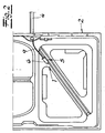
- den Gegenstand nach Fig. 1 nach Unterbringung auf den Rohbau einer Schiebetür,
- Fig. 3
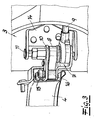
- einen vergrößerten Ausschnitt aus dem Gegenstand nach Fig. 2 auf der anderen Türseite,
- Fig. 4
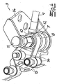
- den Laufwagen aus dem Gegenstand nach Fig. 3 in perspektivischer Darstellung und
- Fig. 5
- einen teilweisen und schematischen Vertikalschnitt durch den Gegenstand nach Fig. 4 im Bereich der Zahnradlagerung.
- Fig. 1
- a drive unit with carriage for a sliding door drive,
- Fig. 2
- 1 after placement on the shell of a sliding door,
- Fig. 3
- an enlarged detail of the article of FIG. 2 on the other side of the door,
- Fig. 4
- the carriage from the article of FIG. 3 in a perspective view and
- Fig. 5
- a partial and schematic vertical section through the article of FIG. 4 in the field of gear storage.
In den Figuren ist ein Schiebetürantrieb 1 für die Schiebetür 2 eines Kraftfahrzeuges dargestellt, wobei die Schiebetür 2 unter Zwischenschaltung eines Laufwagens 3 an einer karosserieseitigen Führungsschiene 4 geführt ist und der Laufwagen 3 mittels eines Antriebsaggregates 5 mit Antriebsmotor 6, Getriebe 7 und Antriebsriemen 8 angetrieben ist.In the figures, a sliding door drive 1 is shown for the sliding
Der Laufwagen 3 und das Antriebsaggregat 5 sind an der Schiebetür 2 befestigt. Das Antriebsaggregat 5 weist einen Elektromotor 6 mit einer flexiblen Welle 9 auf, die auf das Getriebe 7 arbeitet. Das Getriebe 7 ist um die Schwenkachse des Laufwagens 3 gelagert und weist ein mit einem Zahnrad 10 kämmendes Schneckenrad auf. Das nicht gezeigte Schneckenrad ist vollständig gekapselt, so dass insoweit eine Verschmutzung im Betrieb ausgeschlossen wird. Das Zahnrad 10 steht mit dem Antriebsriemen 8 in Eingriff, welcher das Zahnrad 10 teilweise umgreift. Das Zahnrad 10 ist auf einer Lagerachse 11 unter Zwischenschaltung von mehreren Kugellagern 12 gelagert. Nach dem Ausführungsbeispiel ist das Zahnrad 10 mittels zwei in vorgegebenem Abstand voneinander angeordneten Kugellagern 12 und mittels einer zwischen den beiden Kugellagern angeordneten Lagerbuchse 13 auf der Lagerachse 11 gelagert.The
Der Laufwagen 3 weist eine U-förmige Halterung 14 für die Lagerachse 11 auf, die in den beiden U-Schenkeln befestigt, z. B. vernietet ist. Ferner besitzt der Laufwagen 3 an der Führungsschiene 4 abrollende Laufrollen 15 und Umlenkrollen 16 für den karosserieseitig angeschlossenen Antriebsriemen 8. Der Antriebsriemen 8 ist als Zahnriemen ausgebildet.The
Claims (6)
- Sliding door of a motor vehicle containing a sliding door drive, in which the sliding door (2) is guided along a guide rail (4) on the vehicle body with the aid of at least one running carriage (3), said running carriage (3) being driven by a drive unit (5) comprising a drive motor (6), a gear (7) and a driving belt (8), said running carriage (3) and said drive unit (5) being secured to the sliding door (2) and in which the drive unit (5) contains a drive motor (6), e.g. an electric motor with a flexible shaft (9) acting upon the gear (7), characterized in that the gear (7) is arranged around the swiveling axis of the running carriage (3), contains a worm gear meshing with a toothed wheel (10), the toothed wheel (10) engages with the driving belt (8) and the toothed wheel (10) is arranged on a bearing axis (11) by means of one or several roller bearings (12), e.g. ball bearings.
- Sliding door according to claim 1, characterized in that the toothed wheel (10) is arranged on the bearing axis (11) by means of two roller bearings (12) located at a specified distance to each other and by means of a bearing bush (13) situated between the two roller bearings.
- Sliding door according to claims 1 or 2, characterized in that the running carriage (3) contains a U-shaped mounting (14) for the bearing axis (11), secured at the two U-legs by e.g. riveting.
- Sliding door according to one of the claims 1 to 3, characterized in that the running carriage (3) contains rollers (15) for the guide rail (4) and deflection pulleys (16) for the driving belt (8) connected on the vehicle body.
- Sliding door according to one of the claims 1 to 4, characterized in that the driving belt (8) is a toothed belt.
- Sliding door according to one of the claims 1 to 5, characterized in that the worm gear meshing with the toothed wheel (10) is fully encapsulated.
Applications Claiming Priority (2)
| Application Number | Priority Date | Filing Date | Title |
|---|---|---|---|
| DE10341683 | 2003-09-08 | ||
| DE2003141683 DE10341683A1 (en) | 2003-09-08 | 2003-09-08 | Sliding door drive for the sliding door of a motor vehicle |
Publications (2)
| Publication Number | Publication Date |
|---|---|
| EP1512822A1 EP1512822A1 (en) | 2005-03-09 |
| EP1512822B1 true EP1512822B1 (en) | 2007-05-23 |
Family
ID=34129729
Family Applications (1)
| Application Number | Title | Priority Date | Filing Date |
|---|---|---|---|
| EP20040021260 Expired - Lifetime EP1512822B1 (en) | 2003-09-08 | 2004-09-08 | Sliding door drive unit for the sliding door of a vehicle |
Country Status (2)
| Country | Link |
|---|---|
| EP (1) | EP1512822B1 (en) |
| DE (2) | DE10341683A1 (en) |
Family Cites Families (4)
| Publication number | Priority date | Publication date | Assignee | Title |
|---|---|---|---|---|
| DE29821465U1 (en) * | 1998-11-27 | 1999-12-23 | Lunke Ventra Automotive Gmbh | Sliding door with center rail guide |
| US6079767A (en) * | 1999-06-29 | 2000-06-27 | Daimlerchrysler Corporation | Power sliding door for a motor vehicle |
| JP3814520B2 (en) * | 2001-11-15 | 2006-08-30 | アイシン精機株式会社 | Sliding door device for vehicle |
| EP1380718B1 (en) * | 2002-07-08 | 2005-04-06 | Delphi Technologies, Inc. | Device for automatically actuating a sliding door of a vehicle |
-
2003
- 2003-09-08 DE DE2003141683 patent/DE10341683A1/en not_active Withdrawn
-
2004
- 2004-09-08 DE DE200450003864 patent/DE502004003864D1/en not_active Expired - Lifetime
- 2004-09-08 EP EP20040021260 patent/EP1512822B1/en not_active Expired - Lifetime
Also Published As
| Publication number | Publication date |
|---|---|
| DE502004003864D1 (en) | 2007-07-05 |
| DE10341683A1 (en) | 2005-03-31 |
| EP1512822A1 (en) | 2005-03-09 |
Similar Documents
| Publication | Publication Date | Title |
|---|---|---|
| DE102008062763B3 (en) | Coordinate measuring device has drive for vertically mobile component of coordinate measuring device, where drive moving counterweight mass is formed as drive rigid in comparison with traction mechanism | |
| DE102007045882A1 (en) | Power door drive system for use in vehicle i.e. minivan, has power drive mechanism including endless flexible belt for transferring drive torque to pinion gear, to drive door between open and closed positions | |
| EP0775242B1 (en) | Motor-driven window lifter | |
| DE3633336A1 (en) | RACK STEERING, IN PARTICULAR FOR MOTOR VEHICLES | |
| EP1512822B1 (en) | Sliding door drive unit for the sliding door of a vehicle | |
| DE4008061A1 (en) | Drive system for sliding window - has two fixed racks and with directly coupled pinions each side of window | |
| DE29713290U1 (en) | Roller conveyor system | |
| EP0636559B1 (en) | Curved belt conveyor | |
| DE102004027064A1 (en) | Traction mechanism for internal combustion engine, has belt pulley of nonround configuration of driven wheel, and traction device is designed as endless belt and partially surrounds driven wheel | |
| DE19525020A1 (en) | Drive device for translationally adjustable components in motor vehicles | |
| DE3136890C2 (en) | Motorized window regulator | |
| DE3816864A1 (en) | TENSIONING DEVICE FOR A CHAIN DRIVE | |
| DE4422489A1 (en) | Window raising mechanism for vehicle door | |
| DE102007049911A1 (en) | Clamping and guide rail for chain drives | |
| DE102004013207A1 (en) | Tension/slide rail for chain drives of IC engines for motor vehicles has core of elastically flexible plastic on end section to dampen chain vibrations | |
| DE2430163A1 (en) | Windscreen wiper with axial extension - is operated by endless belt drive on wiper stub | |
| EP3068559B1 (en) | Device for machining an endless belt with a belt body made of metal | |
| DE102007039133A1 (en) | tensioner | |
| EP2036748A2 (en) | Control device for controlling air flows in vehicles | |
| DE19509871A1 (en) | Belt drive unit for door panel | |
| DE10324323A1 (en) | Drive for pushing the sliding door of a motor vehicle, comprises a core as power transmission member, with symmetrical rotation bodies arranged as engaging piece for form-locking engagement of drive wheel to the core | |
| DE102004027055A1 (en) | Traction mechanism for use in internal combustion engine, has driven and driving units that are provided with respective toothed belt pulley, where one of the pulleys has ellipse configuration with a preset width | |
| DE102024116287B3 (en) | Belt delivery system for a vehicle and vehicle with belt delivery system | |
| DE202012004830U1 (en) | Actuation unit for a sorting device of piece goods | |
| DE102004032821B4 (en) | Linear wiper, in particular for a motor vehicle |
Legal Events
| Date | Code | Title | Description |
|---|---|---|---|
| PUAI | Public reference made under article 153(3) epc to a published international application that has entered the european phase |
Free format text: ORIGINAL CODE: 0009012 |
|
| AK | Designated contracting states |
Kind code of ref document: A1 Designated state(s): AT BE BG CH CY CZ DE DK EE ES FI FR GB GR HU IE IT LI LU MC NL PL PT RO SE SI SK TR |
|
| AX | Request for extension of the european patent |
Extension state: AL HR LT LV MK |
|
| 17P | Request for examination filed |
Effective date: 20050818 |
|
| AKX | Designation fees paid |
Designated state(s): DE FR IT |
|
| GRAP | Despatch of communication of intention to grant a patent |
Free format text: ORIGINAL CODE: EPIDOSNIGR1 |
|
| GRAS | Grant fee paid |
Free format text: ORIGINAL CODE: EPIDOSNIGR3 |
|
| GRAA | (expected) grant |
Free format text: ORIGINAL CODE: 0009210 |
|
| AK | Designated contracting states |
Kind code of ref document: B1 Designated state(s): DE FR IT |
|
| REF | Corresponds to: |
Ref document number: 502004003864 Country of ref document: DE Date of ref document: 20070705 Kind code of ref document: P |
|
| ET | Fr: translation filed | ||
| PLBE | No opposition filed within time limit |
Free format text: ORIGINAL CODE: 0009261 |
|
| STAA | Information on the status of an ep patent application or granted ep patent |
Free format text: STATUS: NO OPPOSITION FILED WITHIN TIME LIMIT |
|
| 26N | No opposition filed |
Effective date: 20080226 |
|
| PG25 | Lapsed in a contracting state [announced via postgrant information from national office to epo] |
Ref country code: IT Free format text: LAPSE BECAUSE OF FAILURE TO SUBMIT A TRANSLATION OF THE DESCRIPTION OR TO PAY THE FEE WITHIN THE PRESCRIBED TIME-LIMIT Effective date: 20070523 |
|
| REG | Reference to a national code |
Ref country code: FR Ref legal event code: PLFP Year of fee payment: 13 |
|
| REG | Reference to a national code |
Ref country code: FR Ref legal event code: PLFP Year of fee payment: 14 |
|
| REG | Reference to a national code |
Ref country code: FR Ref legal event code: PLFP Year of fee payment: 15 |
|
| P01 | Opt-out of the competence of the unified patent court (upc) registered |
Effective date: 20230529 |
|
| PGFP | Annual fee paid to national office [announced via postgrant information from national office to epo] |
Ref country code: FR Payment date: 20230919 Year of fee payment: 20 Ref country code: DE Payment date: 20230919 Year of fee payment: 20 |
|
| REG | Reference to a national code |
Ref country code: DE Ref legal event code: R071 Ref document number: 502004003864 Country of ref document: DE |