EP1512822B1 - Entraînement de porte coulissante pour la porte coulissante d' un véhicule automobile - Google Patents
Entraînement de porte coulissante pour la porte coulissante d' un véhicule automobile Download PDFInfo
- Publication number
- EP1512822B1 EP1512822B1 EP20040021260 EP04021260A EP1512822B1 EP 1512822 B1 EP1512822 B1 EP 1512822B1 EP 20040021260 EP20040021260 EP 20040021260 EP 04021260 A EP04021260 A EP 04021260A EP 1512822 B1 EP1512822 B1 EP 1512822B1
- Authority
- EP
- European Patent Office
- Prior art keywords
- sliding door
- drive unit
- drive
- gear
- running carriage
- Prior art date
- Legal status (The legal status is an assumption and is not a legal conclusion. Google has not performed a legal analysis and makes no representation as to the accuracy of the status listed.)
- Expired - Lifetime
Links
- 230000005540 biological transmission Effects 0.000 description 4
- 238000004519 manufacturing process Methods 0.000 description 2
- 238000005096 rolling process Methods 0.000 description 2
- 230000006978 adaptation Effects 0.000 description 1
- 230000032683 aging Effects 0.000 description 1
- 238000011109 contamination Methods 0.000 description 1
- 238000005538 encapsulation Methods 0.000 description 1
- 230000001681 protective effect Effects 0.000 description 1
Images


Classifications
-
- E—FIXED CONSTRUCTIONS
- E05—LOCKS; KEYS; WINDOW OR DOOR FITTINGS; SAFES
- E05D—HINGES OR SUSPENSION DEVICES FOR DOORS, WINDOWS OR WINGS
- E05D15/00—Suspension arrangements for wings
- E05D15/06—Suspension arrangements for wings for wings sliding horizontally more or less in their own plane
- E05D15/10—Suspension arrangements for wings for wings sliding horizontally more or less in their own plane movable out of one plane into a second parallel plane
- E05D15/1042—Suspension arrangements for wings for wings sliding horizontally more or less in their own plane movable out of one plane into a second parallel plane with transversely moving carriage
- E05D15/1047—Suspension arrangements for wings for wings sliding horizontally more or less in their own plane movable out of one plane into a second parallel plane with transversely moving carriage specially adapted for vehicles
-
- E—FIXED CONSTRUCTIONS
- E05—LOCKS; KEYS; WINDOW OR DOOR FITTINGS; SAFES
- E05F—DEVICES FOR MOVING WINGS INTO OPEN OR CLOSED POSITION; CHECKS FOR WINGS; WING FITTINGS NOT OTHERWISE PROVIDED FOR, CONCERNED WITH THE FUNCTIONING OF THE WING
- E05F15/00—Power-operated mechanisms for wings
- E05F15/60—Power-operated mechanisms for wings using electrical actuators
- E05F15/603—Power-operated mechanisms for wings using electrical actuators using rotary electromotors
- E05F15/632—Power-operated mechanisms for wings using electrical actuators using rotary electromotors for horizontally-sliding wings
- E05F15/643—Power-operated mechanisms for wings using electrical actuators using rotary electromotors for horizontally-sliding wings operated by flexible elongated pulling elements, e.g. belts, chains or cables
- E05F15/646—Power-operated mechanisms for wings using electrical actuators using rotary electromotors for horizontally-sliding wings operated by flexible elongated pulling elements, e.g. belts, chains or cables allowing or involving a secondary movement of the wing, e.g. rotational or transversal
-
- E—FIXED CONSTRUCTIONS
- E05—LOCKS; KEYS; WINDOW OR DOOR FITTINGS; SAFES
- E05Y—INDEXING SCHEME ASSOCIATED WITH SUBCLASSES E05D AND E05F, RELATING TO CONSTRUCTION ELEMENTS, ELECTRIC CONTROL, POWER SUPPLY, POWER SIGNAL OR TRANSMISSION, USER INTERFACES, MOUNTING OR COUPLING, DETAILS, ACCESSORIES, AUXILIARY OPERATIONS NOT OTHERWISE PROVIDED FOR, APPLICATION THEREOF
- E05Y2201/00—Constructional elements; Accessories therefor
- E05Y2201/40—Motors; Magnets; Springs; Weights; Accessories therefor
- E05Y2201/43—Motors
- E05Y2201/434—Electromotors; Details thereof
-
- E—FIXED CONSTRUCTIONS
- E05—LOCKS; KEYS; WINDOW OR DOOR FITTINGS; SAFES
- E05Y—INDEXING SCHEME ASSOCIATED WITH SUBCLASSES E05D AND E05F, RELATING TO CONSTRUCTION ELEMENTS, ELECTRIC CONTROL, POWER SUPPLY, POWER SIGNAL OR TRANSMISSION, USER INTERFACES, MOUNTING OR COUPLING, DETAILS, ACCESSORIES, AUXILIARY OPERATIONS NOT OTHERWISE PROVIDED FOR, APPLICATION THEREOF
- E05Y2600/00—Mounting or coupling arrangements for elements provided for in this subclass
- E05Y2600/40—Mounting location; Visibility of the elements
- E05Y2600/41—Concealed
-
- E—FIXED CONSTRUCTIONS
- E05—LOCKS; KEYS; WINDOW OR DOOR FITTINGS; SAFES
- E05Y—INDEXING SCHEME ASSOCIATED WITH SUBCLASSES E05D AND E05F, RELATING TO CONSTRUCTION ELEMENTS, ELECTRIC CONTROL, POWER SUPPLY, POWER SIGNAL OR TRANSMISSION, USER INTERFACES, MOUNTING OR COUPLING, DETAILS, ACCESSORIES, AUXILIARY OPERATIONS NOT OTHERWISE PROVIDED FOR, APPLICATION THEREOF
- E05Y2600/00—Mounting or coupling arrangements for elements provided for in this subclass
- E05Y2600/40—Mounting location; Visibility of the elements
- E05Y2600/46—Mounting location; Visibility of the elements in or on the wing
-
- E—FIXED CONSTRUCTIONS
- E05—LOCKS; KEYS; WINDOW OR DOOR FITTINGS; SAFES
- E05Y—INDEXING SCHEME ASSOCIATED WITH SUBCLASSES E05D AND E05F, RELATING TO CONSTRUCTION ELEMENTS, ELECTRIC CONTROL, POWER SUPPLY, POWER SIGNAL OR TRANSMISSION, USER INTERFACES, MOUNTING OR COUPLING, DETAILS, ACCESSORIES, AUXILIARY OPERATIONS NOT OTHERWISE PROVIDED FOR, APPLICATION THEREOF
- E05Y2900/00—Application of doors, windows, wings or fittings thereof
- E05Y2900/50—Application of doors, windows, wings or fittings thereof for vehicles
- E05Y2900/53—Type of wing
- E05Y2900/531—Doors
Definitions
- the invention relates to a sliding door of a motor vehicle with a sliding door drive according to the preamble of claim 1.
- sliding door drives are known in which the body-side drive unit has an electric motor with a flexible shaft and works on a relatively complex gear, the driven wheel meshes with a sliding door side rack.
- a protective cover for the rack is provided, however, the whole transmission is relatively susceptible to contamination (see US 6 079 767, WO 99/09 282).
- the invention has for its object to provide a sliding door drive of the embodiment described above, which is characterized by low manufacturing and assembly costs and characterized by low wear and high durability.
- the invention is based on the recognition that manufacturing costs and assembly costs can be kept much lower when the carriage and the drive unit need not be installed on the body side, but can be accommodated in the sliding door itself. This results in relatively low demands on the shell of the sliding door. This is especially true when the drive unit is a drive motor, for. B. Electric motor having a flexible shaft which operates on the transmission. Because the electric motor with the flexible shaft can be easily arranged at any point in the sliding door. For the carriage and the drive unit only a few attachment points are required.
- the gear which is mounted about the pivot axis of the carriage, a meshing with a gear worm wheel, which is completely encapsulated.
- the gear is expediently engaged with the drive belt, which partially engages around the gear.
- the invention provides that the gear on a bearing axis is mounted with the interposition of one or more rolling bearings, in particular ball bearings.
- the invention further provides that the gear is mounted on the bearing shaft by means of two roller bearings arranged at a predetermined distance from one another and by means of a bearing bush arranged between the two roller bearings.
- the carriage preferably has a U-shaped support for the bearing axis, which is secured in the two U-legs, z. B. is riveted.
- the carriage has rollers for the guide rail and pulleys for the body-side connected drive belt.
- This drive belt is designed as a toothed belt, but in principle can be used in a gear and a chain.
- a gear and a friction wheel for a friction belt can be used as a drive belt.
- the drive belt is made of a material that does not require a length compensation even when aging, so that a belt tensioning device is not required if the drive belt has been tensioned once in the course of assembly.
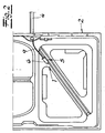
- a sliding door drive 1 is shown for the sliding door 2 of a motor vehicle, wherein the sliding door 2 is guided with the interposition of a carriage 3 on a body-side guide rail 4 and the carriage 3 by means of a drive unit 5 with drive motor 6, gear 7 and drive belt 8 is driven ,
- the carriage 3 and the drive unit 5 are fixed to the sliding door 2.
- the drive unit 5 has an electric motor 6 with a flexible shaft 9, which operates on the transmission 7.
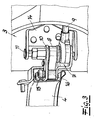
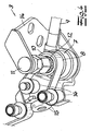
- the gear 7 is mounted about the pivot axis of the carriage 3 and has a meshing with a gear 10 worm wheel.
- the worm wheel not shown, is completely encapsulated, so that extent Pollution during operation is excluded.
- the gear 10 is engaged with the drive belt 8, which engages the gear 10 partially.
- the gear 10 is mounted on a bearing shaft 11 with the interposition of a plurality of ball bearings 12. According to the embodiment, the gear 10 is mounted on the bearing shaft 11 by means of two ball bearings 12 arranged at a predetermined distance from one another and by means of a bearing bush 13 arranged between the two ball bearings.
- the carriage 3 has a U-shaped bracket 14 for the bearing axis 11, which is secured in the two U-legs, z. B. is riveted. Further, the carriage 3 has on the guide rail 4 rolling rollers 15 and pulleys 16 for the body side connected drive belt 8.
- the drive belt 8 is formed as a toothed belt.
Landscapes
- Engineering & Computer Science (AREA)
- Mechanical Engineering (AREA)
- Power-Operated Mechanisms For Wings (AREA)
Claims (6)
- Porte coulissante d'un véhicule à moteur avec un entraînement de porte coulissante, la porte coulissante (2) étant guidée sur un rail de guidage (4) côté carrosserie par l'intermédiaire d'au moins un chariot (3) et le chariot (3) étant entraîné par un dispositif d'entraînement (5) avec moteur d'entraînement (6), engrenage (7) et courroie d'entraînement (8), le chariot (3) et le dispositif d'entraînement (5) étant fixés à la porte coulissante (2), le dispositif d'entraînement (5) présentant un moteur d'entraînement (6) p.ex. un moteur électrique avec un arbre flexible (9) agissant sur l'engrenage (7) caractérisée en ce que l'engrenage (7) est logé autour de l'axe pivotant du chariot (3), une roue à vis sans fin engrenant une roue dentée (10), la roue dentée (10) est en prise avec la courroie dentée (8) et la roue dentée (10) est logée sur un axe de palier (11) par l'intermédiaire d'un ou plusieurs roulements (12), p.ex. roulements à billes.
- Porte coulissante selon la revendication 1 caractérisée en ce que la roue dentée (10) est logée par deux roulements (12) placés à une distance donnée l'un par rapport à l'autre et par un coussinet (13) placé entre les deux roulements sur l'axe de palier (11).
- Porte coulissante selon la revendication 1 ou 2 caractérisée en ce que le chariot (3) présente un support en forme de U (14) pour l'axe de palier (11) fixé, p.ex. riveté, dans les deux branches en U.
- Porte coulissante selon l'une des revendications 1 à 3 caractérisée en ce que le chariot (3) présente des galets de roulement (15) pour le rail de guidage (4) et des galets de renvoi (16) pour la courroie d'entraînement (8) raccordée côté carrosserie.
- Porte coulissante selon l'une des revendications 1 à 4 caractérisée en ce que la courroie d'entraînement (8) est formée en tant que courroie dentée.
- Porte coulissante selon l'une des revendications 1 à 5 caractérisée en ce que la roue dentée engrenée à la roue dentée (10) est entièrement encapsulée.
Applications Claiming Priority (2)
| Application Number | Priority Date | Filing Date | Title |
|---|---|---|---|
| DE10341683 | 2003-09-08 | ||
| DE2003141683 DE10341683A1 (de) | 2003-09-08 | 2003-09-08 | Schiebetürantrieb für die Schiebetür eines Kraftfahrzeuges |
Publications (2)
| Publication Number | Publication Date |
|---|---|
| EP1512822A1 EP1512822A1 (fr) | 2005-03-09 |
| EP1512822B1 true EP1512822B1 (fr) | 2007-05-23 |
Family
ID=34129729
Family Applications (1)
| Application Number | Title | Priority Date | Filing Date |
|---|---|---|---|
| EP20040021260 Expired - Lifetime EP1512822B1 (fr) | 2003-09-08 | 2004-09-08 | Entraînement de porte coulissante pour la porte coulissante d' un véhicule automobile |
Country Status (2)
| Country | Link |
|---|---|
| EP (1) | EP1512822B1 (fr) |
| DE (2) | DE10341683A1 (fr) |
Family Cites Families (4)
| Publication number | Priority date | Publication date | Assignee | Title |
|---|---|---|---|---|
| DE29821465U1 (de) * | 1998-11-27 | 1999-12-23 | Lunke Ventra Automotive Gmbh | Schiebetür mit Mittelschienenführung |
| US6079767A (en) * | 1999-06-29 | 2000-06-27 | Daimlerchrysler Corporation | Power sliding door for a motor vehicle |
| JP3814520B2 (ja) * | 2001-11-15 | 2006-08-30 | アイシン精機株式会社 | 車両用スライドドア装置 |
| EP1380718B1 (fr) * | 2002-07-08 | 2005-04-06 | Delphi Technologies, Inc. | Dispositif pour l'actionnement automatique d'une porte coulissante de véhicule |
-
2003
- 2003-09-08 DE DE2003141683 patent/DE10341683A1/de not_active Withdrawn
-
2004
- 2004-09-08 DE DE200450003864 patent/DE502004003864D1/de not_active Expired - Lifetime
- 2004-09-08 EP EP20040021260 patent/EP1512822B1/fr not_active Expired - Lifetime
Also Published As
| Publication number | Publication date |
|---|---|
| DE502004003864D1 (de) | 2007-07-05 |
| DE10341683A1 (de) | 2005-03-31 |
| EP1512822A1 (fr) | 2005-03-09 |
Similar Documents
| Publication | Publication Date | Title |
|---|---|---|
| DE102008062763B3 (de) | Koordinatenmessgerät mit einem Antrieb für ein vertikal bewegliches Bauteil des Koordinatenmessgerätes | |
| DE102007045882A1 (de) | Riemengetriebene fremdkraftbetätigte Schiebetür mit Zahnstangengetriebe | |
| EP0775242B1 (fr) | Leve-vitre a moteur | |
| DE3633336A1 (de) | Zahnstangenlenkung, insbesondere fuer kraftfahrzeuge | |
| EP1512822B1 (fr) | Entraînement de porte coulissante pour la porte coulissante d' un véhicule automobile | |
| DE4008061A1 (de) | Vorrichtung zum bewegen verschiebbarer teile | |
| DE29713290U1 (de) | Rollenbandförderanlage | |
| EP0636559B1 (fr) | Transporteur à bande courbe | |
| DE102004027064A1 (de) | Zugmitteltrieb für eine Brennkraftmaschine | |
| DE19525020A1 (de) | Antriebseinrichtung für translatorisch verstellbare Bauteile in Kraftfahrzeugen | |
| DE3136890C2 (de) | Motorbetätigter Fensterheber | |
| DE3816864A1 (de) | Spannvorrichtung fuer einen kettentrieb | |
| DE4422489A1 (de) | Fensterheber für ein Kraftfahrzeug | |
| DE102007049911A1 (de) | Spann- und Führungsschiene für Kettentriebe | |
| DE102004013207A1 (de) | Spann- oder Gleitschiene für Kettentriebe von Brennkraftmaschinen von Kraftfahrzeugen | |
| DE2430163A1 (de) | Wischanlage | |
| EP3068559B1 (fr) | Dispositif de traitement d'une bande sans fin possédant un corps métallique | |
| DE102007039133A1 (de) | Riemenspanner | |
| EP2036748A2 (fr) | Dispositif de commande pour commander des flux d'airs dans des véhicules | |
| DE19509871A1 (de) | Antriebseinrichtung | |
| DE10324323A1 (de) | Antriebsvorrichtung zum Verschieben der Schiebetür eines Kraftfahrzeuges | |
| DE102004027055A1 (de) | Kostenoptimierter Zugmitteltrieb | |
| DE102024116287B3 (de) | Gurtbringsystem für ein Fahrzeug und Fahrzeug mit Gurtbringsystem | |
| DE202012004830U1 (de) | Betätigungseinheit für eine Sortiervorrichtung von Stückgütern | |
| DE102004032821B4 (de) | Linearscheibenwischer, insbesondere für ein Kraftfahrzeug |
Legal Events
| Date | Code | Title | Description |
|---|---|---|---|
| PUAI | Public reference made under article 153(3) epc to a published international application that has entered the european phase |
Free format text: ORIGINAL CODE: 0009012 |
|
| AK | Designated contracting states |
Kind code of ref document: A1 Designated state(s): AT BE BG CH CY CZ DE DK EE ES FI FR GB GR HU IE IT LI LU MC NL PL PT RO SE SI SK TR |
|
| AX | Request for extension of the european patent |
Extension state: AL HR LT LV MK |
|
| 17P | Request for examination filed |
Effective date: 20050818 |
|
| AKX | Designation fees paid |
Designated state(s): DE FR IT |
|
| GRAP | Despatch of communication of intention to grant a patent |
Free format text: ORIGINAL CODE: EPIDOSNIGR1 |
|
| GRAS | Grant fee paid |
Free format text: ORIGINAL CODE: EPIDOSNIGR3 |
|
| GRAA | (expected) grant |
Free format text: ORIGINAL CODE: 0009210 |
|
| AK | Designated contracting states |
Kind code of ref document: B1 Designated state(s): DE FR IT |
|
| REF | Corresponds to: |
Ref document number: 502004003864 Country of ref document: DE Date of ref document: 20070705 Kind code of ref document: P |
|
| ET | Fr: translation filed | ||
| PLBE | No opposition filed within time limit |
Free format text: ORIGINAL CODE: 0009261 |
|
| STAA | Information on the status of an ep patent application or granted ep patent |
Free format text: STATUS: NO OPPOSITION FILED WITHIN TIME LIMIT |
|
| 26N | No opposition filed |
Effective date: 20080226 |
|
| PG25 | Lapsed in a contracting state [announced via postgrant information from national office to epo] |
Ref country code: IT Free format text: LAPSE BECAUSE OF FAILURE TO SUBMIT A TRANSLATION OF THE DESCRIPTION OR TO PAY THE FEE WITHIN THE PRESCRIBED TIME-LIMIT Effective date: 20070523 |
|
| REG | Reference to a national code |
Ref country code: FR Ref legal event code: PLFP Year of fee payment: 13 |
|
| REG | Reference to a national code |
Ref country code: FR Ref legal event code: PLFP Year of fee payment: 14 |
|
| REG | Reference to a national code |
Ref country code: FR Ref legal event code: PLFP Year of fee payment: 15 |
|
| P01 | Opt-out of the competence of the unified patent court (upc) registered |
Effective date: 20230529 |
|
| PGFP | Annual fee paid to national office [announced via postgrant information from national office to epo] |
Ref country code: FR Payment date: 20230919 Year of fee payment: 20 Ref country code: DE Payment date: 20230919 Year of fee payment: 20 |
|
| REG | Reference to a national code |
Ref country code: DE Ref legal event code: R071 Ref document number: 502004003864 Country of ref document: DE |