EP1512788A1 - Maschine zur Herstellung und /oder Behandlung einer Materialbahn - Google Patents
Maschine zur Herstellung und /oder Behandlung einer Materialbahn Download PDFInfo
- Publication number
- EP1512788A1 EP1512788A1 EP04002087A EP04002087A EP1512788A1 EP 1512788 A1 EP1512788 A1 EP 1512788A1 EP 04002087 A EP04002087 A EP 04002087A EP 04002087 A EP04002087 A EP 04002087A EP 1512788 A1 EP1512788 A1 EP 1512788A1
- Authority
- EP
- European Patent Office
- Prior art keywords
- roller
- machine according
- pressure roller
- cooling
- cooling roller
- Prior art date
- Legal status (The legal status is an assumption and is not a legal conclusion. Google has not performed a legal analysis and makes no representation as to the accuracy of the status listed.)
- Granted
Links
- 239000000463 material Substances 0.000 title claims description 29
- 238000004519 manufacturing process Methods 0.000 title description 7
- 238000005452 bending Methods 0.000 claims abstract description 9
- 238000001816 cooling Methods 0.000 claims description 99
- 238000001035 drying Methods 0.000 claims description 4
- 230000001960 triggered effect Effects 0.000 claims description 3
- 238000004804 winding Methods 0.000 description 4
- 238000000034 method Methods 0.000 description 3
- 238000003860 storage Methods 0.000 description 3
- 238000010438 heat treatment Methods 0.000 description 2
- XLYOFNOQVPJJNP-UHFFFAOYSA-N water Substances O XLYOFNOQVPJJNP-UHFFFAOYSA-N 0.000 description 2
- 230000006978 adaptation Effects 0.000 description 1
- 230000009172 bursting Effects 0.000 description 1
- 238000009833 condensation Methods 0.000 description 1
- 230000005494 condensation Effects 0.000 description 1
- 239000000498 cooling water Substances 0.000 description 1
- 238000013016 damping Methods 0.000 description 1
- 230000000694 effects Effects 0.000 description 1
- 238000001704 evaporation Methods 0.000 description 1
- 230000008020 evaporation Effects 0.000 description 1
- 238000009413 insulation Methods 0.000 description 1
- 238000005096 rolling process Methods 0.000 description 1
- 238000009423 ventilation Methods 0.000 description 1
Images


Classifications
-
- D—TEXTILES; PAPER
- D21—PAPER-MAKING; PRODUCTION OF CELLULOSE
- D21G—CALENDERS; ACCESSORIES FOR PAPER-MAKING MACHINES
- D21G1/00—Calenders; Smoothing apparatus
-
- D—TEXTILES; PAPER
- D21—PAPER-MAKING; PRODUCTION OF CELLULOSE
- D21F—PAPER-MAKING MACHINES; METHODS OF PRODUCING PAPER THEREON
- D21F5/00—Dryer section of machines for making continuous webs of paper
Definitions
- the invention relates to a machine for the production and / or treatment a material web, in particular paper or board web, with at least one cooling roller, over which the material web is guided.
- a chill roll is required to maintain the temperature of a reduce the paper web coming out of the dryer section that it can be rolled up without the risk of bursting of the Wickels exists. If a web is wound too hot and shrink the individual layers then to the extent to which the winding itself from the outside cooling to the inside, the resulting relative movements lead to Cracks in the web, which cause the winding is not processed can be. Especially at higher operating speeds, with which modern paper machines are operated by the current Material web and the rotating chill roll an air film or so called air boundary layer between the cooling roller and the material web moved in. The retracted air boundary layer can now but the cooling capacity significantly reduce the chill roll. To the performance of the chill roll To be able to exploit fully, must therefore be prevented as possible Air is drawn between the chill roll and the web.
- the invention is based on the object, an improved machine of to create the aforementioned type, in which the problems mentioned above are eliminated.
- a possible collection of a Air boundary layer in the inlet gusset between the cooling roller and material web be reduced to a minimum in order to maximize the optimum To achieve heat transfer between the web and the cooling roller.
- This object is achieved in that the on the Chill roll accumulating material web in the area of the casserole by a pressure roller whose deflection at least substantially the Deflection of the cooling roller corresponds, can be pressed against the cooling roller.
- the deflection of the pressure roller preferably corresponds to the with the chill roller common crest line at least substantially the deflection of the chill roll.
- the deflection lines of the two rolls are thus in the nip direction brought to coincidence, with the deflection of the chill roll of course from their own weight and the operating forces acting on them (Train etc.) results. Due to this training, the collection of a Air boundary layer between the chill roll and the web on a Minimum reduces and thus the heat transfer from the web increased to the cooling roller.
- the deflection of the pressure roller is preferably adjustable, so that an easy adaptation to the respective natural deflection of the Chill roll is possible. Under a natural deflection of the chill roll here is the actual resulting in practical use To understand deflection of this chill roll.
- Machine is the pressure roller gummed.
- the pressure roller with defined, in particular adjustable force against the cooling roller pressed.
- the pressure roller can be stored in particular on levers and on this Lever against the cooling roller be pressed.
- the pressure roller pneumatically and / or hydraulically pressed against the cooling roller.
- pressure rollers acting on the levers may be provided be to press the pressure roller against the cooling roller.
- both the cooling roller and the Pressure roller may be driven in each case.
- only the Chill roll or only the pressure roller to be driven. in principle Such designs are also conceivable in which neither of these two Rolling is aborted.
- the pressure roller must be as small as possible to accommodate the space required to minimize, and as possible vibration-free and as possible without deflection due to its own weight and pressure work.
- the pressure roller is preferably viewed in the direction of the roller axis segmented.
- a segmented pressure roller a plurality of rotatable successive in the direction of the roll axis Roll body include.
- it includes a fixed Axis on which the rotatable roller bodies are placed and on the latter are rotatably mounted.
- the pressure roller can now be built so that they are not in the Natural frequency range of high speeds falls. She has an ideal little one Type, as only the axis natural frequency below the operating frequency lies. The roll segments are due to their short bearing distance in the safe area above the operating frequency. This is achieved that the rotating components of the pressure roller not in bending natural vibrations can not, because they are not due to their natural frequency have to drive. When the roller is raised by the natural frequency driven through the axle.
- the axle can be pre-bent so that the roller deflection due to the dead weight and the pressure force due to the pre-bend can be lifted.
- Machine has the pressure roller along the roll axis multi-layered flexible roll shell.
- the flexible roll shell stored on a fixed axis several times.
- a segmented roller with fixed Axis can thus in particular also a roller with a on the used entire roll surface extending flexible roll body which is stored several times on a fixed axis.
- the fixed axis can for example be pre-bent again.
- the cooling roller with associated pressure roller for example, following a drying section and / or before a Winding be provided.
- Machine can run the pressure roller as a cambered roller be. Is the deflection of the chill roll always constant, so can the namely so-called pinch effect namely achieve by doing that the pressure roller cambered accordingly.
- the pressure roller is designed as a bending compensating roll.
- Bend compensation roller instead of a fixed cambered pressure roller is For example, in such a case conceivable that the deflection the cooling roller operationally changes.
- Machine is the pressure roller provided with a set arc rotatable so that the deflection lines of this pressure roller and the cooling roller can be brought to cover. Do you want the deflection lines bring the chill roll and the pressure roll to coincide, So you can also proceed as follows: You turn the pressure roller with their set bow until the bending lines of both rolls to match.
- the pivoting away of the pressure roller and, if necessary, increasing the temperature of the cooling roller can in particular by a respective Web break can be triggered.
- the pressure roller can only be applied again to the cooling roller or pressed against this, if the material web listed and the temperature of the chill roll back to the lower operating temperature brought is.
- the pressure roller is pivoted away from the cooling roller and the temperature of the chill roll is increased beyond the operating temperature.
- the pressure roller is then re-applied to the chill roll, if the web listed and the chill roll to the lower operating temperature is returned. This will ensure that on the one hand, the cooling roll when performing the web no condensation water on the surface and on the other the web Do not cool together with the chill roll after feeding got to.
- the preferably correspondingly pivotable pressure roller can for example, one behind a calender stack or a calender section be assigned arranged cooling roller.
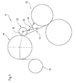
- FIG. 1 shows a schematic partial representation of a machine 10 for the production and / or treatment of a material web 12, in which it is in particular may be a paper or board web.
- the machine 10 comprises at least one cooling roller 14, via which the Material web 12 is guided to, for example, before winding in a reeling device 16 to be cooled accordingly.
- a Pressure roller 22 i. a roll of predetermined or specifiable curvature, pressed against the cooling roller 14.
- the curvature or Deflection of this pressure roller 22 selected so that they at least in Substantially corresponds to the natural deflection of the cooling roller 14.
- the deflection of the pressure roller 22 corresponds to the with the cooling roller 14 common crest line at least substantially the deflection of the cooling roller 14th
- the deflection of the pressure roller 22 can be adjusted in particular be, thereby easily adapting to the respective deflection the cooling roller 14 is made possible.
- the pressure roller 22 may also be rubberized.
- the pressure roller 22 is on levers 24 stored and pressed by these levers 24 against the cooling roller 14. You can, for example, pneumatically and / or hydraulically against the Cooling roller be pressed. In the present case, for example, on the Lever 24 acting pressure cylinder 26 is provided to the pressure roller 22 to press against the cooling roller 14.
- both the cooling roller 14 and the pressure roller 22 each be driven. However, it can only be the chill roll 14 or only the pressure roller 22 to be driven. Basically also conceivable such embodiments, in which none of these two rolls is driven.
- the pressure roller 22 should minimize the space required build small and vibration free as possible without bending work due to its own weight and pressure.
- the pressure roller 22 in the reproduced in the figure 2 Segmented embodiment viewed in the direction of the roll axis.
- the segmented pressure roller comprises 22 several successive in the direction of the roll axis rotatable roller bodies or segments 28 fixed to a fixed one Axis 30 and placed on this by means of a respective storage 32nd are rotatably mounted.
- a segmented roller has the following advantages, among others with itself:
- the roller has an ideal small design, since only the axial natural frequency is below the operating frequency, and the natural frequencies of the roll body or segments are due to their short bearing distance in the safe area above the operating frequency.
- the rotating components The pressure roller so can not get into bending natural vibration because they do not have to drive through their natural frequency.
- booting the Pressure roller is driven through the natural frequency of the axle, However, this due to their high mass, a very high internal damping has.
- the fixed axis 30 can be seen be pre-bent.
- pre-bending for example, the deflection the roller can be lifted by its own weight and pressure.
- the fixed axis 30 is at its two ends via a respective one Bearing 36 mounted on a stand, frame and / or the like.
- a pressure roller with a on the used entire roll surface extending flexible roll body which is stored several times on a fixed axis.
- FIG. 3 shows, in a schematic partial representation, another exemplary example Embodiment of the machine 10 according to the invention.
- this embodiment has at least substantially again the same structure as that of Figure 1, wherein corresponding to each other Parts are assigned the same reference numerals.
- the pressure roller 22 is only then back to the cooling roller 14th can be applied or pressed against them when the material web 12 listed and the temperature of the cooling roller 14 back to the lower Operating temperature is brought.
- the preferably correspondingly pivotable pressure roller 22 can for example, one behind a calender stack or calender section be assigned arranged cooling roller 14. Is for example a Janus calender with two calander stacks or with two in a calander stack arranged calender sections provided, so can behind each calender stack or after each calender section one each Chill roll 14 may be arranged, which is a preferably pivotable Pressure roller 22 is assigned.
- each with such a cooling roller 14 with associated pressure roller 22 is arranged.
- the cooling rollers 14 serve again in this case, the paper as far as possible to cool down and the evaporation of the paper web too minimize.
- To eliminate the air gap between a respective Chill roller 14 and the material or paper web 12 is the material web 12 via the respective pressure roller 22 against the respective cooling roller 14th pressed.
- the cooling rolls 14 are at a flow temperature of 32 ° C (or possibly lower), so that Set a surface temperature of the respective cooling roller 14, the below the dew point indicated above.
- the associated pressure roller 22 is always in this phase against the pressed respective chill roll 14.
- the resulting on the surface of the cooling roller 14 condensate is taken by the material or paper web 12.
- the edge area (tenons, faces and mantle edge area to e.g. mm into the paper web) is isolated so that the surface temperature 20 K higher than the cooled surface of the chill roll 14. Should This insulation will not be sufficient, the front sides of the chill roll ventilated with warm air from the calender ventilation.
- the time is available to prepare the Aufzhouvorgangs is needed. For example, this time is between 4 to 5 min, giving an average heating gradient of at least 3.25 K / min.
- the cooling roller 14 with the entire cooling circuit cooled again to the production temperature of, for example 32 ° C. (Signal "move web"). This is the time for this process Brubreitfahren and closing the calender available. This time For example, it is about 2 minutes, which is an average cooling gradient of 6.5 K / min corresponds.
- the cooling unit must therefore be cooled from, for example, 45 to 32 ° C do not apply the cooling capacity to cool the paper web, since the respective pressure roller 22 during this process, the paper not presses on the respective cooling roller 18 and thus the paper web no has direct contact with the cooling roller. So there is no energy from Paper on the chill roll 14 via.
Landscapes
- Paper (AREA)
- Supply, Installation And Extraction Of Printed Sheets Or Plates (AREA)
- Treatments For Attaching Organic Compounds To Fibrous Goods (AREA)
Abstract
Description
- Figur 1
- eine schematische Teildarstellung einer Maschine zur Herstellung und/oder Behandlung einer Materialbahn mit einer Kühlwalze, über die die Materialbahn geführt und an die die Materialbahn mittels einer Andruckwalze andrückbar ist,
- Figur 2
- eine schematische Seitenansicht der in der Figur 1 dargestellten Andruckwalze und
- Figur 3
- eine schematische Teildarstellung einer weiteren Ausführungsform der Maschine, bei der die mit einem eingestellten Bogen versehene Andruckwalze so drehbar ist, dass die Durchbiegungslinien dieser Andruckwalze und der Kühlwalze zur Deckung bringbar sind.
- 10
- Maschine zur Herstellung und/oder Behandlung einer Materialbahn
- 12
- Materialbahn
- 14
- Kühlwalze
- 16
- Aufwickelvorrichtung
- 18
- Trockenpartie
- 20
- Auflaufstelle
- 22
- Andruckwalze
- 24
- Hebel
- 26
- Andruckzylinder
- 28
- Walzenkörper, -segment
- 30
- feststehende Achse
- 32
- Lagerung
- 34
- Gummibezug
- 36
- Lagerung
- 38
- Bogenhöhe
- 40
- Pfeil
Claims (28)
- Maschine (10) zur Herstellung und/oder Behandlung einer Materialbahn (12), insbesondere Papier- oder Kartonbahn, mit wenigstens einer Kühlwalze (14), über die die Materialbahn (12) geführt ist,
dadurch gekennzeichnet, dass die auf die Kühlwalze (14) auflaufende Materialbahn (12) im Bereich der Auflaufstelle (20) durch eine Andruckwalze (22), deren Durchbiegung zumindest im wesentlichen der Durchbiegung der Kühlwalze (14) entspricht, an die Kühlwalze (14) andrückbar ist. - Maschine nach Anspruch 1,
dadurch gekennzeichnet, dass die Durchbiegung der Andruckwalze (22) auf der mit der Kühlwalze (14) gemeinsamen Scheitellinie zumindest im wesentlichen der Durchbiegung der Kühlwalze (14) entspricht. - Maschine nach Anspruch 1 oder 2,
dadurch gekennzeichnet, dass die Durchbiegung der Andruckwalze (22) einstellbar ist. - Maschine nach einem der vorhergehenden Ansprüche,
dadurch gekennzeichnet, dass die Andruckwalze (22) gummiert ist. - Maschine nach einem der vorhergehenden Ansprüche,
dadurch gekennzeichnet, dass die Andruckwalze (22) mit definierter, insbesondere einstellbarer Kraft gegen die Kühlwalze (14) drückbar ist. - Maschine nach einem der vorhergehenden Ansprüche,
dadurch gekennzeichnet, dass die Andruckwalze (22) auf Hebeln (24) gelagert und über diese Hebel gegen die Kühlwalze (14) drückbar ist. - Maschine nach einem der vorhergehenden Ansprüche,
dadurch gekennzeichnet, dass die Andruckwalze (22) pneumatisch und/oder hydraulisch gegen die Kühlwalze (14) drückbar ist. - Maschine nach einem der vorhergehenden Ansprüche,
dadurch gekennzeichnet, dass auf die Hebel (24) wirkende Andruckzylinder (26) vorgesehen sind, um die Andruckwalze (22) gegen die Kühlwalze (14) zu drücken. - Maschine nach einem der vorhergehenden Ansprüche,
dadurch gekennzeichnet, dass die Kühlwalze (14) und/oder die Andruckwalze (22) jeweils angetrieben ist. - Maschine nach einem der Ansprüche 1 bis 8,
dadurch gekennzeichnet, dass weder die Kühlwalze (14) noch die Andruckwalze (22) angetrieben ist. - Maschine nach einem der vorhergehenden Ansprüche,
dadurch gekennzeichnet, dass die Andruckwalze (22) in Richtung der Walzenachse betrachtet segmentiert ist. - Maschine nach Anspruch 11,
dadurch gekennzeichnet, dass die segmentierte Andruckwalze (22) mehrere in Richtung der Walzenachse aufeinander folgende drehbare Walzenkörper (28) umfasst. - Maschine nach Anspruch 12,
dadurch gekennzeichnet, dass die segmentiere Andruckwalze (22) eine feststehende Achse (30) umfasst, auf die die drehbaren Walzenkörper (28) aufgesetzt und auf der diese drehbar gelagert sind. - Maschine nach Anspruch 13,
dadurch gekennzeichnet, dass die feststehende Achse (30) vorgebogen ist. - Maschine nach einem der Ansprüche 1 bis 10,
dadurch gekennzeichnet, dass die Andruckwalze (22) einen entlang der Walzenachse mehrfach gelagerten flexiblen Walzenmantel besitzt. - Maschine nach Anspruch 15,
dadurch gekennzeichnet, dass der flexible Walzenmantel auf einer feststehenden Achse (30) mehrfach gelagert ist. - Maschine nach Anspruch 16,
dadurch gekennzeichnet, dass die feststehende Achse (30) vorgebogen ist. - Maschine nach einem der vorhergehenden Ansprüche,
dadurch gekennzeichnet, dass die Kühlwalze (14) mit zugeordneter Andruckwalze (22) im Anschluss an eine Trockenpartie (18) vorgesehen ist. - Maschine nach einem der vorhergehenden Ansprüche,
dadurch gekennzeichnet, dass die Andruckwalze (22) als bombierte Walze ausgeführt ist. - Maschine nach einem der vorhergehenden Ansprüche,
dadurch gekennzeichnet, dass die Andruckwalze (22) als Biegeausgleichswalze ausgeführt ist. - Maschine nach einem der vorhergehenden Ansprüche,
dadurch gekennzeichnet, dass die mit einem eingestellten Bogen versehene Andruckwalze (22) so drehbar ist, dass die Durchbiegungslinien dieser Andruckwalze (22) und der Kühlwalze (14) zur Deckung bringbar sind. - Maschine nach einem der vorhergehenden Ansprüche,
dadurch gekennzeichnet, dass die Andruckwalze (22) vor einem jeweiligen Neuaufführen der Materialbahn (12) auf die Kühlwalze (14) von der Kühlwalze (14) wegschwenkbar ist. - Maschine nach Anspruch 22,
dadurch gekennzeichnet, dass vor einem jeweiligen Neuaufführen der Materialbahn (12) auf die Kühlwalze (14) überdies die Temperatur der Kühlwalze (14) erhöhbar ist. - Maschine nach Anspruch 23,
dadurch gekennzeichnet, dass die Temperatur der Kühlwalze (14) gleichzeitig mit dem Wegschwenken der Andruckwalze (22) erhöhbar ist. - Maschine nach einem der vorhergehenden Ansprüche,
dadurch gekennzeichnet, dass das Wegschwenken der Andruckwalze (22) und gegebenenfalls das Erhöhen der Temperatur der Kühlwalze (14) durch einen jeweiligen Bahnabriss auslösbar ist. - Maschine nach einem der vorhergehenden Ansprüche,
dadurch gekennzeichnet, dass die Andruckwalze (22) erst dann wieder an die Kühlwalze (14) anlegbar bzw. gegen diese andrückbar ist, wenn die Materialbahn (12) aufgeführt und die Temperatur der Kühlwalze (14) wieder auf die niedrigere Betriebstemperatur gebracht ist. - Maschine nach einem der vorhergehenden Ansprüche,
dadurch gekennzeichnet, dass die vorzugsweise verschwenkbare Andruckwalze (22) einer hinter einem Kalanderstack oder einem Kalanderabschnitt angeordneten Kühlwalze (14) zugeordnet ist. - Maschine nach Anspruch 27,
dadurch gekennzeichnet, dass ein Janus-Kalander mit zwei Kalanderstacks oder mit zwei in einem Kalanderstack angeordneten Kalanderabschnitten vorgesehen und hinter jedem Kalanderstack bzw. nach jedem Kalanderabschnitt jeweils eine Kühlwalze (14) angeordnet ist, der eine vorzugsweise verschwenkbare Andruckwalze (22) zugeordnet ist.
Applications Claiming Priority (2)
| Application Number | Priority Date | Filing Date | Title |
|---|---|---|---|
| DE10341118 | 2003-09-05 | ||
| DE10341118A DE10341118A1 (de) | 2003-09-05 | 2003-09-05 | Maschine zur Herstellung und/oder Behandlung einer Materialbahn |
Publications (2)
| Publication Number | Publication Date |
|---|---|
| EP1512788A1 true EP1512788A1 (de) | 2005-03-09 |
| EP1512788B1 EP1512788B1 (de) | 2007-11-14 |
Family
ID=34129670
Family Applications (1)
| Application Number | Title | Priority Date | Filing Date |
|---|---|---|---|
| EP04002087A Expired - Lifetime EP1512788B1 (de) | 2003-09-05 | 2004-01-30 | Maschine zur Herstellung und /oder Behandlung einer Materialbahn |
Country Status (3)
| Country | Link |
|---|---|
| EP (1) | EP1512788B1 (de) |
| AT (1) | ATE378468T1 (de) |
| DE (2) | DE10341118A1 (de) |
Cited By (1)
| Publication number | Priority date | Publication date | Assignee | Title |
|---|---|---|---|---|
| DE102007011020A1 (de) | 2007-03-07 | 2008-09-11 | Voith Patent Gmbh | Bahnkühlung |
Citations (1)
| Publication number | Priority date | Publication date | Assignee | Title |
|---|---|---|---|---|
| DE19826063A1 (de) * | 1998-06-12 | 1999-12-23 | Voith Sulzer Papiertech Patent | Kühleinrichtung für eine Materialbahn |
-
2003
- 2003-09-05 DE DE10341118A patent/DE10341118A1/de not_active Withdrawn
-
2004
- 2004-01-30 AT AT04002087T patent/ATE378468T1/de active
- 2004-01-30 DE DE502004005475T patent/DE502004005475D1/de not_active Expired - Lifetime
- 2004-01-30 EP EP04002087A patent/EP1512788B1/de not_active Expired - Lifetime
Patent Citations (1)
| Publication number | Priority date | Publication date | Assignee | Title |
|---|---|---|---|---|
| DE19826063A1 (de) * | 1998-06-12 | 1999-12-23 | Voith Sulzer Papiertech Patent | Kühleinrichtung für eine Materialbahn |
Cited By (1)
| Publication number | Priority date | Publication date | Assignee | Title |
|---|---|---|---|---|
| DE102007011020A1 (de) | 2007-03-07 | 2008-09-11 | Voith Patent Gmbh | Bahnkühlung |
Also Published As
| Publication number | Publication date |
|---|---|
| EP1512788B1 (de) | 2007-11-14 |
| DE502004005475D1 (de) | 2007-12-27 |
| DE10341118A1 (de) | 2005-03-31 |
| ATE378468T1 (de) | 2007-11-15 |
Similar Documents
| Publication | Publication Date | Title |
|---|---|---|
| DE69508422T2 (de) | Wickelmaschine mit angehobener wickellaufschiene | |
| DE4035986C2 (de) | Kalander für den On-line-Anschluß an eine Papiermaschine | |
| DE69916798T2 (de) | Vorrichtung und verfahren zum kontinuierlichen aufwickeln von bahnmaterial | |
| DE102009046053A1 (de) | Verfahren und Vorrichtung zum Öffnen eines Nips | |
| EP0997415B1 (de) | Wickelmaschine | |
| EP1512788B1 (de) | Maschine zur Herstellung und /oder Behandlung einer Materialbahn | |
| EP4004281B1 (de) | Schuhpresse | |
| EP4004280B1 (de) | Presseneinheit | |
| EP1156155A2 (de) | Trockenpartie | |
| EP0652992A1 (de) | Presse einer papiermaschine für dünne papiere. | |
| EP1335066B1 (de) | Verfahren und Vorrichtung zur Herstellung und Behandlung einer Papierbahn | |
| DE202016000260U1 (de) | Pressenvorrichtung | |
| DE112007002325T5 (de) | Schnellöffnen eines Walzensatzes eines Mehrwalzenkalanders | |
| AT10750U1 (de) | Kalandrierungsverfahren und mehrwalzenkalander zur produktion einer faserbahn entweder mit einer glänzenden oder einer matten oberfläche | |
| EP1586697B1 (de) | Papiermaschine | |
| EP1586698A1 (de) | Trockenanordnung | |
| EP1331306B1 (de) | Walze mit einer Antriebseinheit | |
| EP1739228B1 (de) | Maschine zur Herstellung einer Faserstoffbahn | |
| DE9011461U1 (de) | Umlenkwalze zur Verwendung vorzugsweise in einer Ein-Sieb-Trockengruppe | |
| WO2003071028A1 (de) | Glättvorrichtung | |
| DE20319984U1 (de) | Mehrwalzenkalander | |
| DE8915517U1 (de) | Einseitige Wellpappenmaschine | |
| DE10137063A1 (de) | Verfahren und Wickelmaschine zum kontinuierlichen Aufwickeln einer Materialbahn | |
| DE4026774A1 (de) | Mehrwalzen-glaettwerk | |
| AT505568B1 (de) | Einstellung des abstands eines saugkastens von einer gegenwalze |
Legal Events
| Date | Code | Title | Description |
|---|---|---|---|
| PUAI | Public reference made under article 153(3) epc to a published international application that has entered the european phase |
Free format text: ORIGINAL CODE: 0009012 |
|
| AK | Designated contracting states |
Kind code of ref document: A1 Designated state(s): AT BE BG CH CY CZ DE DK EE ES FI FR GB GR HU IE IT LI LU MC NL PT RO SE SI SK TR |
|
| AX | Request for extension of the european patent |
Extension state: AL LT LV MK |
|
| 17P | Request for examination filed |
Effective date: 20050425 |
|
| AKX | Designation fees paid |
Designated state(s): AT DE FI SE |
|
| RAP1 | Party data changed (applicant data changed or rights of an application transferred) |
Owner name: VOITH PATENT GMBH |
|
| GRAP | Despatch of communication of intention to grant a patent |
Free format text: ORIGINAL CODE: EPIDOSNIGR1 |
|
| GRAS | Grant fee paid |
Free format text: ORIGINAL CODE: EPIDOSNIGR3 |
|
| GRAA | (expected) grant |
Free format text: ORIGINAL CODE: 0009210 |
|
| AK | Designated contracting states |
Kind code of ref document: B1 Designated state(s): AT DE FI SE |
|
| REG | Reference to a national code |
Ref country code: SE Ref legal event code: TRGR |
|
| REF | Corresponds to: |
Ref document number: 502004005475 Country of ref document: DE Date of ref document: 20071227 Kind code of ref document: P |
|
| PLBE | No opposition filed within time limit |
Free format text: ORIGINAL CODE: 0009261 |
|
| STAA | Information on the status of an ep patent application or granted ep patent |
Free format text: STATUS: NO OPPOSITION FILED WITHIN TIME LIMIT |
|
| 26N | No opposition filed |
Effective date: 20080815 |
|
| PGFP | Annual fee paid to national office [announced via postgrant information from national office to epo] |
Ref country code: SE Payment date: 20110113 Year of fee payment: 8 |
|
| PGFP | Annual fee paid to national office [announced via postgrant information from national office to epo] |
Ref country code: DE Payment date: 20120123 Year of fee payment: 9 |
|
| PGFP | Annual fee paid to national office [announced via postgrant information from national office to epo] |
Ref country code: FI Payment date: 20120313 Year of fee payment: 9 |
|
| REG | Reference to a national code |
Ref country code: SE Ref legal event code: EUG |
|
| PG25 | Lapsed in a contracting state [announced via postgrant information from national office to epo] |
Ref country code: SE Free format text: LAPSE BECAUSE OF NON-PAYMENT OF DUE FEES Effective date: 20120131 |
|
| PGFP | Annual fee paid to national office [announced via postgrant information from national office to epo] |
Ref country code: AT Payment date: 20120313 Year of fee payment: 9 |
|
| REG | Reference to a national code |
Ref country code: AT Ref legal event code: MM01 Ref document number: 378468 Country of ref document: AT Kind code of ref document: T Effective date: 20130131 |
|
| PG25 | Lapsed in a contracting state [announced via postgrant information from national office to epo] |
Ref country code: FI Free format text: LAPSE BECAUSE OF NON-PAYMENT OF DUE FEES Effective date: 20130130 Ref country code: AT Free format text: LAPSE BECAUSE OF NON-PAYMENT OF DUE FEES Effective date: 20130131 Ref country code: DE Free format text: LAPSE BECAUSE OF NON-PAYMENT OF DUE FEES Effective date: 20130801 |
|
| REG | Reference to a national code |
Ref country code: DE Ref legal event code: R119 Ref document number: 502004005475 Country of ref document: DE Effective date: 20130801 |