EP1512600B1 - Valve de frein de stationnement à commande manuelle pour frein de stationnement a ressort accumulateur d'un rémorque - Google Patents
Valve de frein de stationnement à commande manuelle pour frein de stationnement a ressort accumulateur d'un rémorque Download PDFInfo
- Publication number
- EP1512600B1 EP1512600B1 EP04019797A EP04019797A EP1512600B1 EP 1512600 B1 EP1512600 B1 EP 1512600B1 EP 04019797 A EP04019797 A EP 04019797A EP 04019797 A EP04019797 A EP 04019797A EP 1512600 B1 EP1512600 B1 EP 1512600B1
- Authority
- EP
- European Patent Office
- Prior art keywords
- housing
- stroke
- parking valve
- slider
- parking
- Prior art date
- Legal status (The legal status is an assumption and is not a legal conclusion. Google has not performed a legal analysis and makes no representation as to the accuracy of the status listed.)
- Expired - Lifetime
Links
- 230000010196 hermaphroditism Effects 0.000 claims description 2
- 238000013022 venting Methods 0.000 abstract description 2
- 230000000694 effects Effects 0.000 description 9
- 230000013011 mating Effects 0.000 description 5
- 238000006073 displacement reaction Methods 0.000 description 4
- 238000007789 sealing Methods 0.000 description 4
- 230000035939 shock Effects 0.000 description 4
- 239000011324 bead Substances 0.000 description 3
- 239000000428 dust Substances 0.000 description 3
- 230000009471 action Effects 0.000 description 2
- 230000004323 axial length Effects 0.000 description 2
- 230000008859 change Effects 0.000 description 2
- 230000006870 function Effects 0.000 description 2
- 239000002184 metal Substances 0.000 description 2
- 238000010008 shearing Methods 0.000 description 2
- 230000007704 transition Effects 0.000 description 2
- 238000004891 communication Methods 0.000 description 1
- 230000001419 dependent effect Effects 0.000 description 1
- 230000000994 depressogenic effect Effects 0.000 description 1
- 238000005553 drilling Methods 0.000 description 1
- 239000013013 elastic material Substances 0.000 description 1
- 238000000605 extraction Methods 0.000 description 1
- 238000003780 insertion Methods 0.000 description 1
- 230000037431 insertion Effects 0.000 description 1
- 230000003993 interaction Effects 0.000 description 1
- 239000007788 liquid Substances 0.000 description 1
- 238000012545 processing Methods 0.000 description 1
- 230000008719 thickening Effects 0.000 description 1
- 238000012549 training Methods 0.000 description 1
Images



Classifications
-
- B—PERFORMING OPERATIONS; TRANSPORTING
- B60—VEHICLES IN GENERAL
- B60T—VEHICLE BRAKE CONTROL SYSTEMS OR PARTS THEREOF; BRAKE CONTROL SYSTEMS OR PARTS THEREOF, IN GENERAL; ARRANGEMENT OF BRAKING ELEMENTS ON VEHICLES IN GENERAL; PORTABLE DEVICES FOR PREVENTING UNWANTED MOVEMENT OF VEHICLES; VEHICLE MODIFICATIONS TO FACILITATE COOLING OF BRAKES
- B60T15/00—Construction arrangement, or operation of valves incorporated in power brake systems and not covered by groups B60T11/00 or B60T13/00
- B60T15/02—Application and release valves
- B60T15/04—Driver's valves
- B60T15/041—Driver's valves controlling auxiliary pressure brakes, e.g. parking or emergency brakes
-
- B—PERFORMING OPERATIONS; TRANSPORTING
- B60—VEHICLES IN GENERAL
- B60T—VEHICLE BRAKE CONTROL SYSTEMS OR PARTS THEREOF; BRAKE CONTROL SYSTEMS OR PARTS THEREOF, IN GENERAL; ARRANGEMENT OF BRAKING ELEMENTS ON VEHICLES IN GENERAL; PORTABLE DEVICES FOR PREVENTING UNWANTED MOVEMENT OF VEHICLES; VEHICLE MODIFICATIONS TO FACILITATE COOLING OF BRAKES
- B60T13/00—Transmitting braking action from initiating means to ultimate brake actuator with power assistance or drive; Brake systems incorporating such transmitting means, e.g. air-pressure brake systems
- B60T13/10—Transmitting braking action from initiating means to ultimate brake actuator with power assistance or drive; Brake systems incorporating such transmitting means, e.g. air-pressure brake systems with fluid assistance, drive, or release
- B60T13/24—Transmitting braking action from initiating means to ultimate brake actuator with power assistance or drive; Brake systems incorporating such transmitting means, e.g. air-pressure brake systems with fluid assistance, drive, or release the fluid being gaseous
- B60T13/26—Compressed-air systems
- B60T13/38—Brakes applied by springs or weights and released by compressed air
- B60T13/385—Control arrangements therefor
-
- B—PERFORMING OPERATIONS; TRANSPORTING
- B60—VEHICLES IN GENERAL
- B60T—VEHICLE BRAKE CONTROL SYSTEMS OR PARTS THEREOF; BRAKE CONTROL SYSTEMS OR PARTS THEREOF, IN GENERAL; ARRANGEMENT OF BRAKING ELEMENTS ON VEHICLES IN GENERAL; PORTABLE DEVICES FOR PREVENTING UNWANTED MOVEMENT OF VEHICLES; VEHICLE MODIFICATIONS TO FACILITATE COOLING OF BRAKES
- B60T17/00—Component parts, details, or accessories of power brake systems not covered by groups B60T8/00, B60T13/00 or B60T15/00, or presenting other characteristic features
- B60T17/18—Safety devices; Monitoring
- B60T17/22—Devices for monitoring or checking brake systems; Signal devices
Definitions
- the invention relates to a parking valve for the manual operation of a spring-loaded parking brake of a trailer, with a housing having two connections for a leading to the release chamber of the spring brake cylinder release line and a line for supply air and a vent port, one in the housing sliding and sealing over a total stroke between two limited by stops limit end positions, protruding from the housing slide, which carries relative to the terminals arranged seals, and with a force threshold to be overcome during manual operation.
- a parking valve can be designed as a singular valve with housing, slide and corresponding connections and used within a spring brake system of a trailer.
- the parking valve may also be part of a structural unit, which additionally comprises a release valve and / or at least the emergency brake device of a trailer brake valve.
- the parking valve and the release valve are constructed in a very similar manner, ie they have as essential components a housing with a bore in which a seal provided with slide over a total stroke between two end positions is displaced.
- the parking valve is used to change between parking position and driving position. In this case, the parking position in which the spring brake is energized, the withdrawn end position of the slider assigned while ventilated in the retracted end position corresponding to the position driving the release chamber of the spring brake cylinder and thus the spring brake is released, unless there are other operating conditions.
- a parking valve of the type described above is from the DE 198 53 718 A1 known.
- a slide between two end positions over a total stroke is displaceable. A part of the slide is led out of the housing, so that the manual operation is possible.
- the housing of the parking valve several connections are realized.
- the slide has seals and constrictions to provide the desired flow connections in the two end positions. Zwitter einen may arise between these end positions, in which the region of a connection of the relevant seal is only partially covered, so that a clear flow guidance is not present.
- the friction to be overcome during displacement of the slide over the total stroke is essentially produced by two seals which slide in the bore of the housing when the slide is displaced.
- the known parking valve may be provided in one or all end positions or positions with a force threshold. It may be a spring-loaded ball detent, which is overcome by the operation.
- a locking device In the parking position and a locking device can be provided.
- This force threshold or locking device unfolds its effect only in one or both end positions of the total stroke, so that there makes the force threshold to be overcome locally noticeable.
- the stroke between the two end positions is free of a force threshold.
- the invention has for its object to provide a parking valve of the type described above, which provides the user with increased operating safety in the manual operation available. In addition, should be avoided Zwitterwolfen while driving.
- the parking valve is initially formed as it is known in the prior art, that is, the various connections are realized on the housing side by these are arranged distributed radially and / or axially over the housing of the parking valve. From a connection leads a release line to the release chamber of the spring brake cylinder. There is also provided a vent port, which either leads directly to the atmosphere, but can also serve to connect a line with which a vent hole arranged elsewhere can be reached. Between the slide and the housing stop pairs are provided which limit the two end positions and position, so that the slider is displaceable over the total stroke formed between the stop pairs between its two end positions back and forth.
- the slide has circumferential seals, usually in the form of inserted in grooves O-rings, which are realized on rib-shaped circumferential beads of the slider, so that result between these beads connecting line sections.
- the arrangement and dimensioning of the seals is matched to the arrangement of the connections.
- the force threshold is arranged mislaid in a partial stroke, that is, it no longer exerts its effect on the point End positions, but at least outside an end position over a partial stroke, so that, as it forms a threshold area, which must be overcome in the manual operation. This should result in leaving at least one of the two end positions initially a slight displaceability of the slider. Subsequently, the partial stroke should be effective, over the course of which is to overcome an increased friction by the force threshold. Thus, the user is forced to spend to overcome the Colourhubs an increased force, which is noticeable in marked contrast to the previously used comparatively lower displacement force. This then reliably and reproducibly almost inevitably reaches the other end position, so that the risk of manual incorrect operations is at least reduced.
- the force threshold or the force threshold area is provided by the interaction of a friction member and a cooperating, extending in the direction of the total stroke of the slider over a partial stroke counter surface. During the passage of this partial lift increased friction occurs.
- the mating surface is positioned relative to the friction member so that at least one of the two end positions remains free of the force threshold. In particular, this is the end position, which is associated with the inserted end position of the slider.
- the friction member may advantageously be formed as an inserted into a groove O-ring.
- O-ring is a low-cost item and requires for its attachment and placement only a small effort in the processing of the parts of the parking valve.
- the friction member for example in the form of a slotted resilient metal ring or in another way. It is only important that the contact between the friction member and the counter surface, the relatively increased, easily noticeable by the user increased friction occurs.
- the two possibilities When the friction member is arranged on the slider, the counter surface is arranged on the housing side. If the friction member is arranged on the housing side, the counter surface is realized in the housing.
- An inserted into a groove O-ring as a friction member can additionally serve to provide a sealing effect against the ingress of dust and / or liquid into the interior of the housing.
- the mating surface is provided on one or both ends with run-on slopes, ie with inclined surfaces that facilitate entry of the O-ring relative to the mating surface, without shearing effects on the friction member made of elastic material or with resilient behavior occur.
- the occupied by the contact under increased friction between the friction member and mating surface with the force threshold partial lift can be advantageously positioned relative to the total stroke between the two end positions that the partial stroke is traversed during withdrawal of the slide.
- the reached when pressing the slider into the housing end position thus remains free of increased friction. It may be provided following this end position, a relatively short part stroke held over which the slider is initially slightly displaced when pulling out. Only then does the partial stroke with the increased friction, which is thus noticeable in clear contrast by the user. With the reaching of the end position after pulling out the slide, the increased friction can be maintained, since this position is normally assigned to the loading state of the parking brake, ie the vented release chamber.
- the partial stroke may have an extension in the direction of the total stroke of the slider, which corresponds to approximately half of the total stroke or more.
- no local force threshold but a force threshold area with increased friction is sought.
- the occupied by the contact under increased friction between the friction member and mating surface with the force threshold or the force threshold range should be positioned so relative to the total stroke between the two end positions that hermaphrodites of the parking valve are included or covered so that such Zwitterwolfen not unintentionally while driving can be taken by acting shocks and vibrations.
- the resulting difference between total stroke and partial stroke under increased friction differential stroke which can be overcome relatively easily, then always ends at the beginning of the partial stroke with the increased friction, so that hybrid positions are avoided.
- Fig. 1 shows a parking valve 1 with its housing 2, flanged to a housing block 3, which forms a central part of an assembled unit.
- the housing block 3 may be formed in its interior as shown. But it may also be a trailer brake valve or just an emergency brake.
- the housing block 3 has a connection 4, from which a line 5 leads to a reservoir 6 for compressed air on the trailer.
- the housing block 3 also has a connection 7, from which a control line 8 leads to a combined spring brake cylinder 9.
- the control line 8 is connected to the brake chamber 10 of the service brake part of the spring brake cylinder 9.
- a release line 12 leads to a release chamber 13 of the spring storage part of the spring brake cylinder 9.
- the spring storage part of the spring brake cylinder. 9 is also formed in a known manner and has a memory spring 14, are attracted to the spring brake with the vented release chamber 13, so the trailer is held, for example, in stalled parking position.
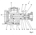
- the parking valve 1 has in its housing 2 a bore 15 in which a slide 16 is guided sliding and sealing.
- the slider 16 has spaced apart beads, in the region in grooves seals 17 and 18 are arranged. Between the seals 17 and 18, the slider 16 has a constriction 19, which serves to establish an air connection.
- the slider 16 also carries a friction member 20 which, as shown, is formed as an O-ring. However, the friction member 20 may also be formed as a slotted metal ring or otherwise.
- the friction member 20 is associated with a counter surface 21 which is tuned in diameter, length and position to the arrangement of the friction member 20.
- the friction member 20 is located in the in Fig.
- the slide 16 has an extension 23 which is led out of the housing 2 of the parking valve 1 and ends in an operating knob 24, the manual actuation of the Parking valve 1 is used.
- a conical inclined surface 25 is formed or provided, which forms a run-on slope for the friction member 20 when pulling out of the housing.
- the actuating head 24 forms with the end face of the housing 2 a stop 26 or a pair of stops, which limits the manual insertion of the slider 16 in the housing 2.
- an end position of the slider 16 is fixed in the housing 2, from which the possible stroke of the slider 16 relative to the housing 2 begins.
- the other end position is achieved in the pulled-out state of the slider 16 from the housing 2 and is in Fig. 2 shown (parking position).
- a stop 27 which is formed at a step at the transition of the central part of the slider 16 to its extension 23.
- the stop 27 is associated with a counter-stop 28 on the housing 2.
- two terminals 29 and 30 are further realized.
- a channel 31 or at least a line is connected, which is permanently in communication with the reservoir 6.
- the release line 12 is connected, which leads to the release chamber 13. This can be done in a singular parking valve 1 in a direct manner, in an assembled valve unit, as in Fig. 1 represented over the housing block 3 and its terminal 11th
- the terminals 29 and 30 are arranged on the housing side axially and at a distance and in coordination with the axial length of the constriction 18 and the position of the seals 17 and 18.
- a vent port 32 is further provided, which leads to the atmosphere.
- the housing 2 of the parking valve 1 is hermetically sealed with a cover 33.
- the maneuvering valve 34 which is also manually operated, is used for Rangier thoroughlyen, thus enabling the cancellation of the braking effect of the parked trailer in one end position and the hard braking of the trailer in the other end position.
- the maneuvering valve 34 is basically similar or identical to the parking valve 1 and connected accordingly. All that is missing is the friction member 20 on the slide.
- the housing 35 of the maneuvering valve 34 is formed in accordance with the housing 2 of the parking valve 1, in which case only the use of the venting port 32 is missing and in its place the supply line 36 is connected.
- the basic structure, the operation and the occurring mode of action of the maneuvering valve 34 are known in the prior art. Since the present invention relates to the parking valve 1, its mode of action will be described below:
- the slider 16 of the parking valve 1 is located in the in Fig. 1 illustrated depressed position in the position ride, this end position is limited by the stops 26.
- the friction member 20 is located at some axial distance from the counter surface 21 and the inclined surface 25, so that when pulling out of the slider 16 from the in Fig. 1 illustrated position of the slider 16 first passes through a partial stroke, in which the friction of the slider 16 to be overcome is determined solely by the sliding friction of the seals 17 and 18 with the bore 15.
- the slider 16 can be moved relatively easily over this partial stroke.
- the dimensioning of the partial stroke in the axial direction is dimensioned such that the seal 17 does not reach the Verschneidungsbohrung of the terminal 30 with the bore 15 during the partial stroke.
- the friction member 20 comes into contact with the inclined surface 25, so that the friction member 20 without shearing the z. B. made of rubber O-rings in the area of the counter surface 21 occurs and is compressed. This achieves the beginning of a force threshold.
- a force threshold results which continues over a force threshold region as long as the friction member 20 is in frictional contact with the counter surface 21.
- this partial stroke extends under increased friction up to the end position (parking), according to Fig. 2 is reached.
- the seal 17 has safely passed over the intersection of the terminal 30 in the housing 2 and again provided sealing effect with the bore 15 so that now the release line 12 head side and lid side vented through the vent port 32 and thus the spring brake is tightened.
- the trailer is stalled and is in parking position.
- the slider 16 may be in Fig. 2 shown withdrawn parking position not leave automatically, but is dependent on a meaningful manual operation.
- the parking valve is manually operated, ie the slider 16 in the in Fig. 1 transferred driving position shown.
- the partial stroke must be covered under increased friction, followed by the partial stroke with comparatively reduced friction. With this obvious and perceptible activity it is ensured that the in Fig. 1 shown end position is reached manually.
- the total stroke of the slider 16 is divided relative to the housing 2 in a first partial stroke 37 and a second partial stroke 38, which in Fig. 2 are indicated.
- the partial stroke 37 takes place with comparatively little friction.
- the partial stroke 38 can be covered or passed through only under increased friction, so that the force threshold thus formed extends over the axial length of the partial stroke 38.
- the partial stroke 38 ends here with the end of the second end position, which limits the total stroke.
- the embodiment of 3 and 4 is basically similar to the embodiment of the Fig. 1 and 2 , Only the geometric arrangement of the friction member 20 and the counter surface 21 and the associated stops 26, 27, 28 is made here so that the total stroke is divided into three Operahübe 37, 38, 39.
- the partial stroke 38 has the increased friction, while the partial strokes 37 and 39 can be passed through relatively easily. It can be seen that in this embodiment, the end position in the pulled-out state is free of increased friction.
- the arrangement and limitation of the sub-hub 38 to a central region of the total stroke helps that this force range is detected with the manual operation in one direction or another with certainty, passed through and exceeded, so that reliably reaches the other end position in the manual operation become.
- an inclined surface 40 can be realized, which fulfills a corresponding function as the inclined surface 25.
- the actuating head 24 extends here like a sleeve over an extension of the housing 2 and works with a seal 41 together, so that in this respect a dust tightness is achieved. This helps to prevent the ingress of dust into the interior of the parking valve and thus not to change the increased friction over the sectionhub 38.
- FIGS. 5 and 6 is basically similar to the embodiments of the Fig. 1 to 4 , Unlike there, however, here the friction member 20 is arranged on the side of the housing 2, while the counter surface 21 is formed by a thickening on the extension 23 of the slider 16.
- the total stroke is also divided here into the partial strokes 37 and 38, wherein the partial stroke 37 with the relatively lower friction, the inserted end position ( Fig. 5 ) or begins there, while the pulled out end position (parking) in Fig. 6 is reached and limits the partial stroke 38.
- FIGS. 7 and 8 follows the preceding embodiments.
- the friction member 20 is arranged on the side of the housing 2, while the counter surface 21 is formed on the slider 16.
- the total stroke of the slider 16 is divided relative to the housing 2 in three Operahübe 37, 38 and 39.
- the partial strokes 37 and 39 are those with comparatively little friction, while the partial stroke 38 is disposed in the middle region, excluding both end positions, and represents the force threshold or the force range.
- the elements are arranged and formed in geometric association with one another such that hybrid positions for a partial connection of the connections 29 and 30 are avoided.
- the axial extent of the stroke 38 is greater than the range at which hybrid positions could be set or occupied. This not only serves to increase the safety during manual operation, but also excludes also Zwitterwolfen due to acting shocks and vibrations while driving.
Landscapes
- Engineering & Computer Science (AREA)
- Transportation (AREA)
- Mechanical Engineering (AREA)
- Valves And Accessory Devices For Braking Systems (AREA)
- Braking Systems And Boosters (AREA)
Claims (10)
- Valve de frein de stationnement (1) pour l'actionnement manuel d'un frein de stationnement à accumulation d'une remorque, comportant un boîtier (2), qui est muni de deux raccords (29, 30) pour une conduite de desserrage (12) menant vers la chambre de desserrage (13) du cylindre de frein à accumulation (9), et une conduite (31) pour air de stockage, ainsi qu'un raccord de purge d'air (32), une coulisse (16), qui est montée dans le boîtier (2) de manière étanche et coulissante sur une course complète entre deux positions de fin de course limitées par des butées (26, 27, 28) et s'avançant hors du boîtier (2) et qui porte des garnitures d'étanchéité (17, 18) disposées par rapport aux raccords (29, 30), et comportant un seuil de force à surmonter lors de l'actionnement manuel, caractérisée en ce qu'un organe de friction (20) et une surface complémentaire (21), qui coopère avec ce dernier et couvre une course partielle (38) dans la direction de la course complète de la coulisse (16), sont prévus pour former le seuil de force et sont en contact avec un frottement plus élevé sur la course partielle (38) entre les deux positions de fin de course.
- Valve de frein de stationnement selon la revendication 1, caractérisée en ce que la surface complémentaire (21) est positionnée par rapport à l'organe de friction (20), de telle sorte qu'au moins une des deux positions de fin de course reste libre du seuil de force.
- Valve de frein de stationnement selon la revendication 1 ou 2, caractérisée en ce que l'organe de friction (20) est réalisé sous la forme d'un joint torique posé dans une rainure.
- Valve de frein de stationnement selon au moins une des revendications 1 à 3, caractérisée en ce que l'organe de friction (20) est disposé sur la coulisse (16) ou dans le boîtier (2).
- Valve de frein de stationnement selon au moins une des revendications 1 à 4, caractérisée en ce que la surface complémentaire (21) est disposée dans le boîtier (2) ou sur la coulisse (16).
- Valve de frein de stationnement selon au moins une des revendications 1 à 5, caractérisée en ce que la surface complémentaire (21), sur une extrémité ou sur les deux extrémités, est munie de rampes d'introduction (25, 40).
- Valve de frein de stationnement selon au moins une des revendications 1 à 6, caractérisée en ce que la course partielle (38), occupée par le seuil de force généré par le contact à frottement plus élevé entre l'organe de friction (20) et la surface complémentaire (21), est positionnée par rapport à la course complète entre les deux positions de fin de course, de telle sorte que la coulisse (16) parcourt la course partielle (38) pendant son déplacement vers l'extérieur.
- Valve de frein de stationnement selon au moins une des revendications 1 à 7, caractérisée en ce que la course partielle (38) est positionnée par rapport à la course complète à l'exclusion des deux positions de fin de course.
- Valve de frein de stationnement selon au moins une des revendications 1 à 8, caractérisée en ce que la course partielle (38), dans la direction de la course complète de la coulisse (16), a une dimension qui correspond sensiblement à la moitié de la course complète.
- Valve de frein de stationnement selon au moins une des revendications 1 à 9, caractérisée en ce que la course partielle (38), occupée par le seuil de force généré par le contact à frottement plus élevé entre l'organe de friction (20) et la surface complémentaire (21), est positionnée par rapport à la course complète entre les deux positions de fin de course, de telle sorte qu'elle inclut des positions réversibles de la valve de frein de stationnement (1).
Applications Claiming Priority (2)
| Application Number | Priority Date | Filing Date | Title |
|---|---|---|---|
| DE10341120 | 2003-09-07 | ||
| DE10341120A DE10341120B3 (de) | 2003-09-07 | 2003-09-07 | Parkventil für die manuelle Betätigung einer Federspeicher-Feststellbremse eines Anhängers |
Publications (2)
| Publication Number | Publication Date |
|---|---|
| EP1512600A1 EP1512600A1 (fr) | 2005-03-09 |
| EP1512600B1 true EP1512600B1 (fr) | 2008-03-05 |
Family
ID=34112149
Family Applications (1)
| Application Number | Title | Priority Date | Filing Date |
|---|---|---|---|
| EP04019797A Expired - Lifetime EP1512600B1 (fr) | 2003-09-07 | 2004-08-20 | Valve de frein de stationnement à commande manuelle pour frein de stationnement a ressort accumulateur d'un rémorque |
Country Status (3)
| Country | Link |
|---|---|
| EP (1) | EP1512600B1 (fr) |
| AT (1) | ATE388066T1 (fr) |
| DE (2) | DE10341120B3 (fr) |
Families Citing this family (2)
| Publication number | Priority date | Publication date | Assignee | Title |
|---|---|---|---|---|
| DE102015118290A1 (de) * | 2015-10-27 | 2017-04-27 | Knorr-Bremse Systeme für Nutzfahrzeuge GmbH | Elektro-pneumatische Feststellbremseinrichtung mit redundanter pneumatischer Steuerung |
| DE102018209479A1 (de) | 2018-06-13 | 2019-12-19 | Knorr-Bremse Systeme für Nutzfahrzeuge GmbH | Bedienungssicheres Parkventil |
Family Cites Families (2)
| Publication number | Priority date | Publication date | Assignee | Title |
|---|---|---|---|---|
| DE4226839A1 (de) * | 1991-11-26 | 1993-05-27 | Knorr Bremse Ag | Parkventil fuer anhaengerbremsanlagen mit federspeicher |
| DE19853718C2 (de) * | 1998-11-20 | 2001-05-23 | Knorr Bremse Systeme | Park- und Rangierventil für Anghängefahrzeuge mit einer Federspeicher-Feststellbremse |
-
2003
- 2003-09-07 DE DE10341120A patent/DE10341120B3/de not_active Expired - Lifetime
-
2004
- 2004-08-20 AT AT04019797T patent/ATE388066T1/de not_active IP Right Cessation
- 2004-08-20 EP EP04019797A patent/EP1512600B1/fr not_active Expired - Lifetime
- 2004-08-20 DE DE502004006388T patent/DE502004006388D1/de not_active Expired - Lifetime
Also Published As
| Publication number | Publication date |
|---|---|
| DE10341120B3 (de) | 2005-03-03 |
| ATE388066T1 (de) | 2008-03-15 |
| DE502004006388D1 (de) | 2008-04-17 |
| EP1512600A1 (fr) | 2005-03-09 |
Similar Documents
| Publication | Publication Date | Title |
|---|---|---|
| EP2382520B1 (fr) | Soupape de régulation de pression proportionnelle et son utilisation pour connection hydraulique | |
| DE3874544T2 (de) | Druckdichte steckkupplung. | |
| EP1250547B1 (fr) | Dispositif de raccord d'une conduite de fluide | |
| DE3626882C2 (de) | Schnell lösbares, aufnehmendes Kupplungsstück | |
| DE3433787C2 (fr) | ||
| DE19707041A1 (de) | Schnellverbindevorrichtung | |
| DE2138103A1 (de) | Steckkupplung fuer rohr- und schlauchleitungen | |
| DE69807179T2 (de) | Unter Druck zusammensteckbare Schnellverbindungskupplung | |
| DE102008044819A1 (de) | Hydraulisches Element | |
| DE102008059438A1 (de) | Zylinder, insbesondere Geberzylinder einer hydraulischen Betätigungsvorrichtung für eine Kupplung | |
| EP1636521B1 (fr) | Dispositif de raccordement pour un tuyau ou un element similaire | |
| EP3513111B1 (fr) | Coupleur hydraulique | |
| DE2623934C3 (de) | Steckkupplung zum Verbinden von Gasleitungen | |
| DE2624013C2 (de) | Rohr- oder Schlauchleitungskupplung | |
| DE3639528A1 (de) | Steckkupplung | |
| EP1512600B1 (fr) | Valve de frein de stationnement à commande manuelle pour frein de stationnement a ressort accumulateur d'un rémorque | |
| DE60012901T2 (de) | Kolben- zylinder- vorrichtung mit mittel zur verriegelung der kolbenstange | |
| DE3607975C2 (de) | Buchsenteil einer Rohr- oder Schlauchleitungskupplung | |
| DE3877901T2 (de) | Gegen den leitungsdruck verbindbare rohrkupplung. | |
| EP0051201A1 (fr) | Accouplement pour systèmes hydrauliques | |
| DE3444855C1 (de) | Auch bei unter Druck stehendem Stecker kuppelbare Rohrabreisskupplung fuer insbes. Hydraulikleitungen | |
| DE4300004C2 (de) | Anschlußarmatur für Rohre | |
| EP1361325A1 (fr) | Actionneur pour fermetures des vehicules | |
| DE69715022T2 (de) | Ventileinrichtung | |
| DE2914208A1 (de) | Gleitschutzregelungseinrichtung |
Legal Events
| Date | Code | Title | Description |
|---|---|---|---|
| PUAI | Public reference made under article 153(3) epc to a published international application that has entered the european phase |
Free format text: ORIGINAL CODE: 0009012 |
|
| AK | Designated contracting states |
Kind code of ref document: A1 Designated state(s): AT BE BG CH CY CZ DE DK EE ES FI FR GB GR HU IE IT LI LU MC NL PL PT RO SE SI SK TR |
|
| AX | Request for extension of the european patent |
Extension state: AL HR LT LV MK |
|
| 17P | Request for examination filed |
Effective date: 20050226 |
|
| AKX | Designation fees paid |
Designated state(s): AT BE BG CH CY CZ DE DK EE ES FI FR GB GR HU IE IT LI LU MC NL PL PT RO SE SI SK TR |
|
| GRAP | Despatch of communication of intention to grant a patent |
Free format text: ORIGINAL CODE: EPIDOSNIGR1 |
|
| GRAS | Grant fee paid |
Free format text: ORIGINAL CODE: EPIDOSNIGR3 |
|
| GRAA | (expected) grant |
Free format text: ORIGINAL CODE: 0009210 |
|
| AK | Designated contracting states |
Kind code of ref document: B1 Designated state(s): AT BE BG CH CY CZ DE DK EE ES FI FR GB GR HU IE IT LI LU MC NL PL PT RO SE SI SK TR |
|
| REG | Reference to a national code |
Ref country code: GB Ref legal event code: FG4D Free format text: NOT ENGLISH |
|
| REG | Reference to a national code |
Ref country code: CH Ref legal event code: EP |
|
| REG | Reference to a national code |
Ref country code: IE Ref legal event code: FG4D Free format text: LANGUAGE OF EP DOCUMENT: GERMAN |
|
| REF | Corresponds to: |
Ref document number: 502004006388 Country of ref document: DE Date of ref document: 20080417 Kind code of ref document: P |
|
| GBT | Gb: translation of ep patent filed (gb section 77(6)(a)/1977) |
Effective date: 20080429 |
|
| PG25 | Lapsed in a contracting state [announced via postgrant information from national office to epo] |
Ref country code: ES Free format text: LAPSE BECAUSE OF FAILURE TO SUBMIT A TRANSLATION OF THE DESCRIPTION OR TO PAY THE FEE WITHIN THE PRESCRIBED TIME-LIMIT Effective date: 20080616 Ref country code: FI Free format text: LAPSE BECAUSE OF FAILURE TO SUBMIT A TRANSLATION OF THE DESCRIPTION OR TO PAY THE FEE WITHIN THE PRESCRIBED TIME-LIMIT Effective date: 20080305 |
|
| NLV1 | Nl: lapsed or annulled due to failure to fulfill the requirements of art. 29p and 29m of the patents act | ||
| PG25 | Lapsed in a contracting state [announced via postgrant information from national office to epo] |
Ref country code: PL Free format text: LAPSE BECAUSE OF FAILURE TO SUBMIT A TRANSLATION OF THE DESCRIPTION OR TO PAY THE FEE WITHIN THE PRESCRIBED TIME-LIMIT Effective date: 20080305 Ref country code: SI Free format text: LAPSE BECAUSE OF FAILURE TO SUBMIT A TRANSLATION OF THE DESCRIPTION OR TO PAY THE FEE WITHIN THE PRESCRIBED TIME-LIMIT Effective date: 20080305 |
|
| REG | Reference to a national code |
Ref country code: IE Ref legal event code: FD4D |
|
| PG25 | Lapsed in a contracting state [announced via postgrant information from national office to epo] |
Ref country code: CZ Free format text: LAPSE BECAUSE OF FAILURE TO SUBMIT A TRANSLATION OF THE DESCRIPTION OR TO PAY THE FEE WITHIN THE PRESCRIBED TIME-LIMIT Effective date: 20080305 Ref country code: NL Free format text: LAPSE BECAUSE OF FAILURE TO SUBMIT A TRANSLATION OF THE DESCRIPTION OR TO PAY THE FEE WITHIN THE PRESCRIBED TIME-LIMIT Effective date: 20080305 Ref country code: SK Free format text: LAPSE BECAUSE OF FAILURE TO SUBMIT A TRANSLATION OF THE DESCRIPTION OR TO PAY THE FEE WITHIN THE PRESCRIBED TIME-LIMIT Effective date: 20080305 Ref country code: PT Free format text: LAPSE BECAUSE OF FAILURE TO SUBMIT A TRANSLATION OF THE DESCRIPTION OR TO PAY THE FEE WITHIN THE PRESCRIBED TIME-LIMIT Effective date: 20080805 Ref country code: SE Free format text: LAPSE BECAUSE OF FAILURE TO SUBMIT A TRANSLATION OF THE DESCRIPTION OR TO PAY THE FEE WITHIN THE PRESCRIBED TIME-LIMIT Effective date: 20080605 |
|
| PG25 | Lapsed in a contracting state [announced via postgrant information from national office to epo] |
Ref country code: RO Free format text: LAPSE BECAUSE OF FAILURE TO SUBMIT A TRANSLATION OF THE DESCRIPTION OR TO PAY THE FEE WITHIN THE PRESCRIBED TIME-LIMIT Effective date: 20080305 |
|
| PLBI | Opposition filed |
Free format text: ORIGINAL CODE: 0009260 |
|
| EN | Fr: translation not filed | ||
| PLAX | Notice of opposition and request to file observation + time limit sent |
Free format text: ORIGINAL CODE: EPIDOSNOBS2 |
|
| 26 | Opposition filed |
Opponent name: KNORR-BREMSE SYSTEME FUER NUTZFAHRZEUGE GMBH Effective date: 20081205 |
|
| PG25 | Lapsed in a contracting state [announced via postgrant information from national office to epo] |
Ref country code: IE Free format text: LAPSE BECAUSE OF FAILURE TO SUBMIT A TRANSLATION OF THE DESCRIPTION OR TO PAY THE FEE WITHIN THE PRESCRIBED TIME-LIMIT Effective date: 20080305 Ref country code: DK Free format text: LAPSE BECAUSE OF FAILURE TO SUBMIT A TRANSLATION OF THE DESCRIPTION OR TO PAY THE FEE WITHIN THE PRESCRIBED TIME-LIMIT Effective date: 20080305 |
|
| PLBB | Reply of patent proprietor to notice(s) of opposition received |
Free format text: ORIGINAL CODE: EPIDOSNOBS3 |
|
| PG25 | Lapsed in a contracting state [announced via postgrant information from national office to epo] |
Ref country code: MC Free format text: LAPSE BECAUSE OF NON-PAYMENT OF DUE FEES Effective date: 20080831 |
|
| REG | Reference to a national code |
Ref country code: CH Ref legal event code: PL |
|
| PG25 | Lapsed in a contracting state [announced via postgrant information from national office to epo] |
Ref country code: EE Free format text: LAPSE BECAUSE OF FAILURE TO SUBMIT A TRANSLATION OF THE DESCRIPTION OR TO PAY THE FEE WITHIN THE PRESCRIBED TIME-LIMIT Effective date: 20080305 Ref country code: FR Free format text: LAPSE BECAUSE OF FAILURE TO SUBMIT A TRANSLATION OF THE DESCRIPTION OR TO PAY THE FEE WITHIN THE PRESCRIBED TIME-LIMIT Effective date: 20081226 Ref country code: BG Free format text: LAPSE BECAUSE OF FAILURE TO SUBMIT A TRANSLATION OF THE DESCRIPTION OR TO PAY THE FEE WITHIN THE PRESCRIBED TIME-LIMIT Effective date: 20080605 |
|
| PG25 | Lapsed in a contracting state [announced via postgrant information from national office to epo] |
Ref country code: CH Free format text: LAPSE BECAUSE OF NON-PAYMENT OF DUE FEES Effective date: 20080831 Ref country code: LI Free format text: LAPSE BECAUSE OF NON-PAYMENT OF DUE FEES Effective date: 20080831 |
|
| PG25 | Lapsed in a contracting state [announced via postgrant information from national office to epo] |
Ref country code: BE Free format text: LAPSE BECAUSE OF NON-PAYMENT OF DUE FEES Effective date: 20080831 |
|
| PG25 | Lapsed in a contracting state [announced via postgrant information from national office to epo] |
Ref country code: IT Free format text: LAPSE BECAUSE OF FAILURE TO SUBMIT A TRANSLATION OF THE DESCRIPTION OR TO PAY THE FEE WITHIN THE PRESCRIBED TIME-LIMIT Effective date: 20080305 |
|
| PG25 | Lapsed in a contracting state [announced via postgrant information from national office to epo] |
Ref country code: CY Free format text: LAPSE BECAUSE OF FAILURE TO SUBMIT A TRANSLATION OF THE DESCRIPTION OR TO PAY THE FEE WITHIN THE PRESCRIBED TIME-LIMIT Effective date: 20080305 |
|
| PG25 | Lapsed in a contracting state [announced via postgrant information from national office to epo] |
Ref country code: AT Free format text: LAPSE BECAUSE OF NON-PAYMENT OF DUE FEES Effective date: 20080820 |
|
| PLCK | Communication despatched that opposition was rejected |
Free format text: ORIGINAL CODE: EPIDOSNREJ1 |
|
| PG25 | Lapsed in a contracting state [announced via postgrant information from national office to epo] |
Ref country code: LU Free format text: LAPSE BECAUSE OF NON-PAYMENT OF DUE FEES Effective date: 20080820 Ref country code: HU Free format text: LAPSE BECAUSE OF FAILURE TO SUBMIT A TRANSLATION OF THE DESCRIPTION OR TO PAY THE FEE WITHIN THE PRESCRIBED TIME-LIMIT Effective date: 20080906 |
|
| APBM | Appeal reference recorded |
Free format text: ORIGINAL CODE: EPIDOSNREFNO |
|
| APBP | Date of receipt of notice of appeal recorded |
Free format text: ORIGINAL CODE: EPIDOSNNOA2O |
|
| APAH | Appeal reference modified |
Free format text: ORIGINAL CODE: EPIDOSCREFNO |
|
| PG25 | Lapsed in a contracting state [announced via postgrant information from national office to epo] |
Ref country code: TR Free format text: LAPSE BECAUSE OF FAILURE TO SUBMIT A TRANSLATION OF THE DESCRIPTION OR TO PAY THE FEE WITHIN THE PRESCRIBED TIME-LIMIT Effective date: 20080305 |
|
| APBQ | Date of receipt of statement of grounds of appeal recorded |
Free format text: ORIGINAL CODE: EPIDOSNNOA3O |
|
| PG25 | Lapsed in a contracting state [announced via postgrant information from national office to epo] |
Ref country code: GR Free format text: LAPSE BECAUSE OF FAILURE TO SUBMIT A TRANSLATION OF THE DESCRIPTION OR TO PAY THE FEE WITHIN THE PRESCRIBED TIME-LIMIT Effective date: 20080606 |
|
| APBU | Appeal procedure closed |
Free format text: ORIGINAL CODE: EPIDOSNNOA9O |
|
| PLBN | Opposition rejected |
Free format text: ORIGINAL CODE: 0009273 |
|
| STAA | Information on the status of an ep patent application or granted ep patent |
Free format text: STATUS: OPPOSITION REJECTED |
|
| 27O | Opposition rejected |
Effective date: 20130913 |
|
| REG | Reference to a national code |
Ref country code: DE Ref legal event code: R100 Ref document number: 502004006388 Country of ref document: DE Effective date: 20130913 |
|
| REG | Reference to a national code |
Ref country code: DE Ref legal event code: R082 Ref document number: 502004006388 Country of ref document: DE Representative=s name: REHBERG HUEPPE + PARTNER PATENTANWAELTE PARTG , DE Ref country code: DE Ref legal event code: R081 Ref document number: 502004006388 Country of ref document: DE Owner name: HALDEX BRAKE PRODUCTS AKTIEBOLAG, SE Free format text: FORMER OWNER: HALDEX BRAKE PRODUCTS GMBH, 69123 HEIDELBERG, DE |
|
| REG | Reference to a national code |
Ref country code: GB Ref legal event code: 732E Free format text: REGISTERED BETWEEN 20170112 AND 20170118 |
|
| REG | Reference to a national code |
Ref country code: DE Ref legal event code: R008 Ref document number: 502004006388 Country of ref document: DE Ref country code: DE Ref legal event code: R039 Ref document number: 502004006388 Country of ref document: DE |
|
| REG | Reference to a national code |
Ref country code: DE Ref legal event code: R040 Ref document number: 502004006388 Country of ref document: DE |
|
| PGFP | Annual fee paid to national office [announced via postgrant information from national office to epo] |
Ref country code: GB Payment date: 20230824 Year of fee payment: 20 |
|
| PGFP | Annual fee paid to national office [announced via postgrant information from national office to epo] |
Ref country code: DE Payment date: 20230713 Year of fee payment: 20 |
|
| REG | Reference to a national code |
Ref country code: DE Ref legal event code: R082 Ref document number: 502004006388 Country of ref document: DE Representative=s name: MUELLER SCHUPFNER & PARTNER PATENT- UND RECHTS, DE |
|
| REG | Reference to a national code |
Ref country code: GB Ref legal event code: 732E Free format text: REGISTERED BETWEEN 20240704 AND 20240710 |
|
| REG | Reference to a national code |
Ref country code: DE Ref legal event code: R071 Ref document number: 502004006388 Country of ref document: DE |
|
| REG | Reference to a national code |
Ref country code: GB Ref legal event code: PE20 Expiry date: 20240819 |
|
| PG25 | Lapsed in a contracting state [announced via postgrant information from national office to epo] |
Ref country code: GB Free format text: LAPSE BECAUSE OF EXPIRATION OF PROTECTION Effective date: 20240819 |
|
| PG25 | Lapsed in a contracting state [announced via postgrant information from national office to epo] |
Ref country code: GB Free format text: LAPSE BECAUSE OF EXPIRATION OF PROTECTION Effective date: 20240819 |