EP1512440A1 - Schuh- oder Fusshaltevorrichtung an einem Sportgerät - Google Patents
Schuh- oder Fusshaltevorrichtung an einem Sportgerät Download PDFInfo
- Publication number
- EP1512440A1 EP1512440A1 EP04017910A EP04017910A EP1512440A1 EP 1512440 A1 EP1512440 A1 EP 1512440A1 EP 04017910 A EP04017910 A EP 04017910A EP 04017910 A EP04017910 A EP 04017910A EP 1512440 A1 EP1512440 A1 EP 1512440A1
- Authority
- EP
- European Patent Office
- Prior art keywords
- division
- medial
- link
- lateral
- foot
- Prior art date
- Legal status (The legal status is an assumption and is not a legal conclusion. Google has not performed a legal analysis and makes no representation as to the accuracy of the status listed.)
- Granted
Links
- 230000008901 benefit Effects 0.000 description 10
- 238000012423 maintenance Methods 0.000 description 5
- 229920002994 synthetic fiber Polymers 0.000 description 3
- 239000004952 Polyamide Substances 0.000 description 2
- 230000006978 adaptation Effects 0.000 description 2
- 238000010276 construction Methods 0.000 description 2
- 239000000463 material Substances 0.000 description 2
- 229920002647 polyamide Polymers 0.000 description 2
- 229920002635 polyurethane Polymers 0.000 description 2
- 239000004814 polyurethane Substances 0.000 description 2
- 230000000717 retained effect Effects 0.000 description 2
- 241000287107 Passer Species 0.000 description 1
- 238000004026 adhesive bonding Methods 0.000 description 1
- 230000000295 complement effect Effects 0.000 description 1
- 238000013016 damping Methods 0.000 description 1
- 230000001627 detrimental effect Effects 0.000 description 1
- 230000009365 direct transmission Effects 0.000 description 1
- 230000007717 exclusion Effects 0.000 description 1
- CNQCVBJFEGMYDW-UHFFFAOYSA-N lawrencium atom Chemical compound [Lr] CNQCVBJFEGMYDW-UHFFFAOYSA-N 0.000 description 1
- 210000000878 metatarsophalangeal joint Anatomy 0.000 description 1
- 238000000034 method Methods 0.000 description 1
- 229920000728 polyester Polymers 0.000 description 1
- XLYOFNOQVPJJNP-UHFFFAOYSA-N water Substances O XLYOFNOQVPJJNP-UHFFFAOYSA-N 0.000 description 1
- 238000003466 welding Methods 0.000 description 1
- 238000004804 winding Methods 0.000 description 1
Images






Classifications
-
- A—HUMAN NECESSITIES
- A63—SPORTS; GAMES; AMUSEMENTS
- A63C—SKATES; SKIS; ROLLER SKATES; DESIGN OR LAYOUT OF COURTS, RINKS OR THE LIKE
- A63C10/00—Snowboard bindings
- A63C10/28—Snowboard bindings characterised by auxiliary devices or arrangements on the bindings
- A63C10/285—Pads as foot or binding supports, e.g. pads made of foam
-
- A—HUMAN NECESSITIES
- A63—SPORTS; GAMES; AMUSEMENTS
- A63C—SKATES; SKIS; ROLLER SKATES; DESIGN OR LAYOUT OF COURTS, RINKS OR THE LIKE
- A63C10/00—Snowboard bindings
- A63C10/02—Snowboard bindings characterised by details of the shoe holders
- A63C10/04—Shoe holders for passing over the shoe
-
- A—HUMAN NECESSITIES
- A63—SPORTS; GAMES; AMUSEMENTS
- A63C—SKATES; SKIS; ROLLER SKATES; DESIGN OR LAYOUT OF COURTS, RINKS OR THE LIKE
- A63C10/00—Snowboard bindings
- A63C10/02—Snowboard bindings characterised by details of the shoe holders
- A63C10/04—Shoe holders for passing over the shoe
- A63C10/06—Straps therefor, e.g. adjustable straps
-
- A—HUMAN NECESSITIES
- A63—SPORTS; GAMES; AMUSEMENTS
- A63C—SKATES; SKIS; ROLLER SKATES; DESIGN OR LAYOUT OF COURTS, RINKS OR THE LIKE
- A63C10/00—Snowboard bindings
- A63C10/24—Calf or heel supports, e.g. adjustable high back or heel loops
Definitions
- the invention relates to a device for maintaining a foot or a shoe on a sports apparatus, for which the maintenance of the foot or the shoe is done using at least one link.
- the invention also relates to a link intended to be part of the device.
- Such devices are used for snowboarding or snowboarding, skiing on snow or on water, snowshoe, rollerblading, or whatever.
- a link device generally comprises a lateral part and a medial part which delimit between them a zone of reception of the foot or the shoe, as well a back support member associated with at least one of the lateral and medial portions.
- the rear support element comprises a bearing face, turned towards the reception zone and intended to to receive the back of a lower leg.
- the rear support element also includes a free face opposite to the support face.
- the device further comprises at least one link that extends between lateral and medial parts, each link serving to hold the foot or the shoe in the area Home.
- the link is generally an elongated piece relatively flexible and substantially inextensible. Its flexibility allows it to adapt to the foot or the shoe. His relative Inextensibility promotes the maintenance of the foot or the shoe in the reception area.
- a front edge catch can cause a heave of heel, which is detrimental to driving precision.
- the object of the invention is to remedy these drawbacks and in particular improve the hold of the foot or shoe at the heel, and improve simultaneously maintaining the rear of the lower leg on the rear support element.
- the invention proposes a device for maintaining a foot or a shoe, the device comprising a lateral part and a medial part delimiting a reception zone foot or footwear, and a rear support element associated with at least one of the lateral and medial parts, the rear support element comprising a support surface turned towards the reception area and a free face opposite to the support face, the device comprising still a link that extends between the lateral and medial parts, the link comprising a division before and a rear division.
- the holding device according to the invention is characterized in that the front division of the link is located on the side of the bearing face of the rear support element, and that the rear division is located on the side of the free face of the rear support element.
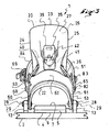
- a holding device 1 allows the temporary maintenance on a board 2 of a shoe 3.
- the holding device 1 comprises a base 4 which extends longitudinally between a rear end 5 and a front end 6.
- the base 4 has an upper face 7 designed to be facing the sole 8 of the shoe 3, and a lower face 9 provided to be above the board 2.
- the base 4 is retained on the board 2 by a means represented in the form of a disc 10, itself retained in the board 2 by screws 11.
- the base 4 is bordered laterally by a lateral flange 12 and a medial flange 13.
- Each of the flanges 12, 13 respectively form a lateral or medial part of the device 1 to define a reception zone 14 of the shoe.
- the flanges 12, 13 along the sole 8 laterally.
- he could be provided other than the flanges 12, 13 to form the lateral and medial parts.
- simple lateral and medial abutments may be suitable.
- the base 4 and the flanges 12, 13 form a single piece made by example in synthetic material.
- the flanges are parts secured to the base by any means, such as gluing, welding, screwing, nesting, or other.
- the device 1 also comprises a rear support element 20, so that the user can take back supports with the lower leg.
- the rear support member 20 comprises a curved plate 21 which extends longitudinally between an attachment end 22 and a free end 23, transversely between a lateral edge 24 and a medial edge 25, and in thickness between a bearing face 26 and a free face 27.
- the bearing face 26 is provided to receive the rear of the lower leg of the user, the rear support element 20 and the base 4 being associated accordingly.
- the rear support element 20 is associated with the flanges 12, 13, for example by means of a hinge 28.
- the latter is oriented substantially along a transverse axis 29 of the device 1.
- the articulation 28 may comprise any component such as a screw, a rivet, a washer, a nut, a pin, or other.
- the hinge 28 allows a movement of approximation of the rear support element 20 to the base 4. A benefit that arises is to facilitate storage.
- rear support element 20 could also be directly associated with the base 4. Or it could be provided that the rear support element 20 is directly attached to the machine, in this case plate 2. It is sufficient to position it on the machine so that it allows the back supports with the lower leg.
- a means for adjusting the position of the rear support element 20 is provided. relative to the base 4.
- This means is represented in the form of holes 30 formed in the side flanges 12 and medial 13. It is for example possible to move the element forward or backward rear support 20 in the direction of the length of the base 4, by disassembly and reassembly of the articulation 28. This makes it possible to adjust the device 1 to the length of a shoe.
- the holes 30 could be arranged to allow a height adjustment, in a direction of approach or distance of the base 4.
- a stop 35 limits the rotation towards the back of the eponymous support element 20.
- the stop 35 comprises a cable 36 which bypasses the element 20.
- the path of the cable 36 can be seen in FIGS. 1, 2 and 3. for example, the cable may comprise a lateral end 37 and a medial end 38.
- Each of the ends 37, 38 is secured to the lateral flange 12 or medial 13 by any medium known to those skilled in the art. The use of a crimped tip may be suitable.
- Each end 37, 38 is secured to the flange 12, 13 substantially close to the front end 6 of the base 4.
- the cable 36 follows each flange 12, 13 in away, to bypass the rear support member 20 in a position further away from the flanges.
- An adjustable shim 39 secured to the rear support element 20 on the side of the face 27, allows to adjust the angular position of the rear support element relative to the base 4.
- the cable 36 passes through two guides 40, 41 of the support element rear 20 on both sides of the wedge 39. Between the guides 40, 41, the cable 36 is held by the wedge 39. It is sufficient to move the wedge 39 closer to or away from the free end 23.
- This means may comprise a screw 42 for tightening or loosen the shim 39 relative to the rear support member 20.
- teeth complementary to the wedge 39 and the rear support element 20 allow positioning from one to the other. These teeth, not shown, are well known to those skilled in the art.
- any other structure to make the stop could be suitable.
- a first link 50 is located forward, at the level of the metatarsophalangeal joint when the foot is held.
- a second link 51 is located aft, at the level of the instep when the foot is held.
- Each of the links 50, 51 extends transversely between the flanges 12, 13.
- the second link 51 comprises a front division 52 and a rear division 53.
- the front division 52 of the link 51 is located on the side of the bearing face 26 of the rear support element 20, and the rear division 53 is located on the side of the free face 27 of the rear support element.
- the rear division 53 of the link 51 includes a foot lateral 60 and a medial foot 61 connected to each other by an arch 62.
- Each of the lateral feet 60 and medial 61 is associated respectively with the lateral flange 12 and medial 13, for example to the aid of the articulation 28 of axis 29.
- the same joint 28 serves to maintain both the rear support element 20 and the rear division 53 of the link 51.
- a benefit that arises is a simplification of construction.
- Another advantage is to confer on the rear division 53 a degree of freedom in rotation along the transverse axis 29. This facilitates the implementation of the rear division 53.
- the arch 62 is more easily plated on the free face 27 of the element rear support 20.
- the feet 60, 61 and the arch 62 form a single piece, made by example from a synthetic material.
- Rear division 53 may include polyurethane, polyester, polyamide, or other.
- the rear division 53 can be expected to give the rear division 53 a relatively small thickness, for example example between 1 and 3 millimeters. This makes it relatively flexible while leaving it substantially inextensible. An advantage that results is better adaptability to forms of a shoe or the rear support element.
- rear division can also be built from several pieces, assembled by any means known to those skilled in the art.
- the front division 52 is associated with the rear division 53. It is represented in the form of an association of three portions, which are a first attachment portion 63, a portion of cover 64 of the shoe, and a second attachment portion 65.
- the first portion 63 has an attachment end 66 and a free end 67.
- the fastening end 66 is connected to the lateral leg 60 by a side fastener.
- the latter is represented in the form of a hinge, made for example by means of a rivet 68.
- a first connecting means is provided for removably connecting the portion of cover 64 to the first portion 63, the free end 67 of the first attachment portion 63 being above the cover portion 64.
- This means includes, for example, a ratchet clamp mechanism 69 attached to the cover portion 64, at a first end 70 of the latter.
- the binding means of the cover portion 64 to the first portion 63 also comprises a series of teeth 71 shaped on the first portion 63. The teeth 71 are distributed from the free end 67 to near the articulation 68.
- the second attachment portion 65 has a fastening end 80 and a free end 81.
- the attachment end 80 is connected to the medial foot 61 by a fastener medial.
- the latter is represented in the form of a joint, made for example at using a rivet 82.
- a second connecting means is provided to adjustably connect the portion of cover 64 to the second portion 65, the free end 81 of the second attachment portion 65 being above the cover portion 64.
- This means comprises for example a screw 83 which is screwed into the cover portion 64, at a second end 84 of the latter. The screw 83 passes through one of the holes 85 drilled in the second portion 65.
- the user can make the second end 84 of the portion of cover 64 is near the medial foot 61.
- the position adjustment, the portion of coverage 64 relative to the second portion 65, is rarely changed. It is intended to take into account the clutter of the shoe.
- the two joints are substantially along a transverse axis of the device, which allows the front division 52 to uniformly cover the shoe.
- joints could be made by other means such as screws, trunnions, or other.
- front division 52 ties to the 53 rear division could be made by other means, such as a winding around a passer, or other.
- first and second portions 63, 65 preferably comprise respectively a band 86, 87 elongated made from a synthetic material, such as a polyamide or polyurethane armed or not. Each band 86, 87 extends in length respectively since the attachment end 66, 80 to the free end 67, 81 of the attachment portion 63, 65.
- the cover portion 64 in turn has an elongated shape. It is expanding length between the first 70 and second 84 ends.
- Each portion 63, 64, 65 is more or less flexible. Its curvature is variable, and it can fold to fit the foot or the shoe.
- various holes 88, 89 are arranged respectively in the lateral feet 60 and medial 61. These holes 88, 89 allow to modify the relative positions of the divisions before 52 and back 53 of the link 51. It suffices to assign a lateral 68 or medial attachment 82 to a lateral 88 or 89 medial hole selected.
- An advantage resulting from it is an improvement in the adaptation of device 1 to size or shape of a shoe. In the end it is the entirety of the link 51 which is stamped on the shoe and on the rear support element 20. This is why the games between the shoe and the base 4 or the rear support element 20 are very small, or even zero.
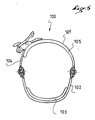
- the second example is shown in Figure 6.
- a 100 back link is shown in section similar to FIG. 5.
- the rear link 100 comprises a front division 101 and a rear division 102, the latter passing behind a rear support element 103.
- the second example uses a reduced forward division 101. This one has fewer pieces to cover the shoe. Indeed, it only presents a first attachment portion 104 and a covering portion 105, to the exclusion of any other portion. This construction is simpler and more economical.
- a holding device 120 comprises a base 121 which extends longitudinally between a rear end 122 and a front end 123.
- the base 121 is bordered laterally by a lateral flange 124 and by a medial flange 125.
- a rear support element 126 of the device 120 is associated with the base 121, by a means represented in the form of a hinge axis 127. articulation is made between an attachment end 128 of the rear support member 126 and the flanges 124, 125.
- the device 120 comprises a rear link 140, with a division before 141 and a rear division 142.
- the latter 142 comprises a lateral foot 143 and a medial foot 144 both associated with the base 121.
- the association is realized in the form of a articulation, along an axis 145, lateral feet 143 and medial 144 on lateral flanges 124 and medial 125.
- the hinge pins 127, 145 of the rear support element 126 and the rear link 140 are so here different. This adjusts the angular position of the rear support member 126 regardless of the position of the rear link 140.
- the hinge axis 127 of the support element rear 126 is closer to the base 121 that the hinge axis 145 of the rear link 140. It it follows that for the same tightening force of the link 140, the rear division 142 rotates according to an angle value greater than the rear support element 126. A benefit that follows is a greater stability of the angular position of the rear support element 126.
- the perforated portion may be lined with one or more damping cushions.
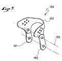
- a rear division 153 of a link includes a lateral foot 160 and a medial foot 161 connected by an arch 162.
- the lateral feet 160 and medial 161 are hinged relative to the arch 162 along a transverse axis 163.
- the relative articulation of the feet 160, 161 and the arch 162 displaces the degree of freedom by rotation of the arch upwards, in a direction away from the base.
- the invention is made from materials and according to implementation techniques known to those skilled in the art.
- each of the front and rear divisions is associated with the base.
- association can be direct or indirect.
- each division may have flexible or rigid portions.
- the portions can be articulated together in the manner of the links of a chain.
Landscapes
- Footwear And Its Accessory, Manufacturing Method And Apparatuses (AREA)
- Agricultural Machines (AREA)
Applications Claiming Priority (2)
| Application Number | Priority Date | Filing Date | Title |
|---|---|---|---|
| FR0310366A FR2859109B1 (fr) | 2003-09-02 | 2003-09-02 | Dispositif de maintien d'un pied ou d'une chaussure sur un engin de sport |
| FR0310366 | 2003-09-02 |
Publications (2)
| Publication Number | Publication Date |
|---|---|
| EP1512440A1 true EP1512440A1 (de) | 2005-03-09 |
| EP1512440B1 EP1512440B1 (de) | 2009-11-04 |
Family
ID=34130700
Family Applications (1)
| Application Number | Title | Priority Date | Filing Date |
|---|---|---|---|
| EP04017910A Expired - Lifetime EP1512440B1 (de) | 2003-09-02 | 2004-07-29 | Schuh- oder Fusshaltevorrichtung an einem Sportgerät |
Country Status (7)
| Country | Link |
|---|---|
| US (1) | US7232147B2 (de) |
| EP (1) | EP1512440B1 (de) |
| JP (1) | JP3107396U (de) |
| CN (1) | CN1597033A (de) |
| AT (1) | ATE447432T1 (de) |
| DE (1) | DE602004023905D1 (de) |
| FR (1) | FR2859109B1 (de) |
Families Citing this family (32)
| Publication number | Priority date | Publication date | Assignee | Title |
|---|---|---|---|---|
| DE10305764B4 (de) * | 2003-02-11 | 2007-04-12 | Goodwell International Ltd., Tortola | Snowboardbindung |
| US7316412B2 (en) * | 2003-09-02 | 2008-01-08 | Salomon S.A. | Device for retaining a foot or a boot on a sports apparatus |
| FR2872434B1 (fr) * | 2004-07-01 | 2006-09-15 | Skis Rossignol Sa Sa | Fixation de chaussure de sport sur planche de glisse avec chaussage/dechaussage facilite |
| ITMI20051428A1 (it) * | 2005-07-22 | 2007-01-23 | Core S R L | Fascia di trattenimento per attacchi particolarmente per tavole da neve |
| US7306241B2 (en) * | 2005-08-29 | 2007-12-11 | The Burton Corporation | Strap for snowboard boots or bindings |
| US8016315B2 (en) | 2005-09-30 | 2011-09-13 | Flow Sports, Inc. | Modular binding for sports board |
| FR2896425B1 (fr) * | 2006-01-26 | 2008-04-18 | Salomon Sa | Dispositif d'accueil d'un pied ou d'une chaussure sur un engin de sport |
| US20070182130A1 (en) * | 2006-02-06 | 2007-08-09 | Laser Brian K | Snowboard binding |
| WO2007112125A2 (en) * | 2006-03-24 | 2007-10-04 | Goodwell International, Ltd. | Locking attachment and adjustment device |
| US7571924B2 (en) * | 2006-06-14 | 2009-08-11 | Rick White | Rotatable snowboard boot binding apparatus |
| EP2108412A1 (de) * | 2006-07-07 | 2009-10-14 | The Burton Corporation | Bindung für ein Gleitbrett |
| FR2910338B1 (fr) * | 2006-12-20 | 2009-06-05 | Salomon Sa | Article comprenant un lien de retenue ou de serrage d'un pied ou d'une chaussure |
| US8469372B2 (en) | 2008-10-23 | 2013-06-25 | Bryce M. Kloster | Splitboard binding apparatus |
| US8763210B2 (en) * | 2010-01-15 | 2014-07-01 | Gv Snowshoes | Locking device for a buckle |
| FR2958556B1 (fr) * | 2010-04-12 | 2012-12-21 | Salomon Sas | Dispositif d'accueil d'un pied ou d'une chaussure sur un engin de glisse. |
| US8763209B2 (en) | 2011-08-23 | 2014-07-01 | The Burton Corporation | Ratchet buckle and strap assembly |
| FR2985915B1 (fr) * | 2012-01-25 | 2014-01-10 | Salomon Sas | Piece de reglage d'un article de sport |
| WO2013110725A1 (en) * | 2012-01-26 | 2013-08-01 | Hiturn As | Adjustment system for straps on snowboard bindings |
| US9238168B2 (en) | 2012-02-10 | 2016-01-19 | Bryce M. Kloster | Splitboard joining device |
| USD673234S1 (en) * | 2012-03-21 | 2012-12-25 | O'hara Timothy | Bi-lateral support for a snowboard binding |
| US9266010B2 (en) * | 2012-06-12 | 2016-02-23 | Tyler G. Kloster | Splitboard binding with adjustable leverage devices |
| US9254434B2 (en) | 2014-06-23 | 2016-02-09 | Tzy Shenq Enterprise Co., Ltd. | Fixation seat for ski shoe |
| US9114309B1 (en) * | 2014-06-23 | 2015-08-25 | Tzy Shenq Enterprise Co., Ltd. | Fixation seat for ski shoe |
| US9220970B1 (en) | 2014-11-14 | 2015-12-29 | The Burton Corporation | Snowboard binding and boot |
| US9149711B1 (en) | 2014-11-14 | 2015-10-06 | The Burton Corporation | Snowboard binding and boot |
| EP3218073B1 (de) | 2014-11-14 | 2021-05-19 | The Burton Corporation | Snowboard-bindung |
| US9604122B2 (en) | 2015-04-27 | 2017-03-28 | Bryce M. Kloster | Splitboard joining device |
| US10029165B2 (en) | 2015-04-27 | 2018-07-24 | Bryce M. Kloster | Splitboard joining device |
| US10105588B1 (en) * | 2017-09-26 | 2018-10-23 | Chasen Massey | Snowboard binding with adjustment memory |
| US11117042B2 (en) | 2019-05-03 | 2021-09-14 | Bryce M. Kloster | Splitboard binding |
| US11938394B2 (en) | 2021-02-22 | 2024-03-26 | Bryce M. Kloster | Splitboard joining device |
| CN115282586B (zh) * | 2022-09-01 | 2025-02-14 | 湖北翔驰运动用品有限公司 | 一种便于调整快穿固定器扎带 |
Citations (4)
| Publication number | Priority date | Publication date | Assignee | Title |
|---|---|---|---|---|
| US5713587A (en) * | 1995-08-11 | 1998-02-03 | Morrow Snowboards, Inc. | Attachment system for snowboards |
| US5771609A (en) * | 1993-10-01 | 1998-06-30 | Salomon S.A. | Snowboard boot with inner stiffening assembly |
| US6206403B1 (en) | 1998-06-26 | 2001-03-27 | Nike International, Inc. | Snowboard strap binding |
| US6276708B1 (en) * | 1998-01-20 | 2001-08-21 | Roy L. Hogstedt | Snowboard boot and binding assembly |
Family Cites Families (10)
| Publication number | Priority date | Publication date | Assignee | Title |
|---|---|---|---|---|
| US5727797A (en) * | 1996-02-06 | 1998-03-17 | Preston Binding Company | Snowboard binding assembly with adjustable forward lean backplate |
| FR2746604B1 (fr) * | 1996-03-29 | 1998-05-29 | Salomon Sa | Dispositif de retenue d'une chaussure sur une planche avec element d'appui dorsal articule |
| IT1283817B1 (it) * | 1996-08-21 | 1998-04-30 | Pida S R L | Attacco per tavola da neve |
| US6648365B1 (en) * | 1997-01-08 | 2003-11-18 | The Burton Corporation | Snowboard binding |
| DE19739223C2 (de) * | 1997-09-08 | 2002-04-25 | Reinhard Hansen | Snowboardbindung |
| FR2801514B1 (fr) * | 1999-11-25 | 2001-12-21 | Rossignol Sa | Fixation de surf |
| US6631919B1 (en) * | 2000-01-06 | 2003-10-14 | The Burton Corporation | Wing-shaped leg support for a highback |
| JP4915829B2 (ja) * | 2001-06-14 | 2012-04-11 | 株式会社カーメイト | スノーボード用ビンディング |
| US6511091B1 (en) * | 2001-08-03 | 2003-01-28 | Chorng-Chyi Su | Fixing structure for skis |
| US6889997B2 (en) * | 2003-01-31 | 2005-05-10 | Shimano Inc. | Snowboard binding |
-
2003
- 2003-09-02 FR FR0310366A patent/FR2859109B1/fr not_active Expired - Fee Related
-
2004
- 2004-07-29 EP EP04017910A patent/EP1512440B1/de not_active Expired - Lifetime
- 2004-07-29 AT AT04017910T patent/ATE447432T1/de not_active IP Right Cessation
- 2004-07-29 DE DE602004023905T patent/DE602004023905D1/de not_active Expired - Lifetime
- 2004-08-26 JP JP2004005111U patent/JP3107396U/ja not_active Expired - Lifetime
- 2004-08-31 US US10/929,367 patent/US7232147B2/en not_active Expired - Fee Related
- 2004-09-01 CN CN200410088097.2A patent/CN1597033A/zh active Pending
Patent Citations (4)
| Publication number | Priority date | Publication date | Assignee | Title |
|---|---|---|---|---|
| US5771609A (en) * | 1993-10-01 | 1998-06-30 | Salomon S.A. | Snowboard boot with inner stiffening assembly |
| US5713587A (en) * | 1995-08-11 | 1998-02-03 | Morrow Snowboards, Inc. | Attachment system for snowboards |
| US6276708B1 (en) * | 1998-01-20 | 2001-08-21 | Roy L. Hogstedt | Snowboard boot and binding assembly |
| US6206403B1 (en) | 1998-06-26 | 2001-03-27 | Nike International, Inc. | Snowboard strap binding |
Also Published As
| Publication number | Publication date |
|---|---|
| CN1597033A (zh) | 2005-03-23 |
| DE602004023905D1 (de) | 2009-12-17 |
| EP1512440B1 (de) | 2009-11-04 |
| JP3107396U (ja) | 2005-02-03 |
| US7232147B2 (en) | 2007-06-19 |
| ATE447432T1 (de) | 2009-11-15 |
| US20050046150A1 (en) | 2005-03-03 |
| FR2859109A1 (fr) | 2005-03-04 |
| FR2859109B1 (fr) | 2005-11-11 |
Similar Documents
| Publication | Publication Date | Title |
|---|---|---|
| EP1512440B1 (de) | Schuh- oder Fusshaltevorrichtung an einem Sportgerät | |
| EP1162898B1 (de) | Schuh mit einer kippgestängelasche zur versteifung von der vorderseite des schuhs, insbesondere eines snowboardstiefels | |
| EP1559454B1 (de) | Schuh- oder Fusshaltevorrichtung an einem Sportgerät | |
| EP1147791B1 (de) | Schuhbindung für Snowboard oder Rollbrett | |
| EP0812552A1 (de) | Spannvorrichtung mit Zahnriemen und Schnappverschluss | |
| EP0704174A1 (de) | Gleitsportschuh | |
| FR2820049A1 (fr) | Dispositif de retenue d'une chaussure sur un engin de sport | |
| EP0959964B1 (de) | Schuh für gleitsportarten mit einem gleitgerät geeignet zur zusammenarbeit mit einem solchen schuh | |
| FR2820048A1 (fr) | Dispositif de retenue d'une chaussure sur un engin de sport | |
| EP2374513B1 (de) | Vorrichtung zur Aufnahme eines Fußes oder eines Schuhs auf einem Gleitgerät | |
| EP1118360A1 (de) | Rückhaltevorrichtung für einen Schuh auf einem Sportgerät | |
| FR2896425A1 (fr) | Dispositif d'accueil d'un pied ou d'une chaussure sur un engin de sport | |
| EP2954797A1 (de) | Sportschuh | |
| EP1327467A1 (de) | Vorrichtung zum Befestigen eines Schuhs auf einem Sportgerät | |
| EP1433504A1 (de) | Vorrichtung zum Befestigen eines Schuhs auf einem Sportgerät | |
| EP1900399A1 (de) | Artikel, der ein Halte- oder Befestigungselement mit Magnet für einen Fuß oder Schuh umfasst | |
| EP3741436B1 (de) | Bindungsvorrichtung zur befestigung eines snowboardschuhs auf einem snowboard | |
| EP1491240B1 (de) | Fuss- oder Schuhhaltevorrichtung | |
| EP1512441B1 (de) | Schuh- oder Fusshaltevorrichtung an einem Sportgerät | |
| FR2878757A1 (fr) | Dispositif de maintien d'un pied ou d'une chaussure sur un engin de sport | |
| EP1530987B1 (de) | Snowboardbindung | |
| FR2871069A1 (fr) | Dispositif de maintien d'un pied ou d'une chaussure | |
| FR2752147A1 (fr) | Chaussure de sport | |
| EP1923105B1 (de) | Vorrichtung zur Aufnahme eines Fußes oder eines Schuhs auf einem Sportgerät | |
| FR2769239A1 (fr) | Dispositif de retenue d'une chaussure sur une planche de glisse destinee a la pratique du surf sur neige |
Legal Events
| Date | Code | Title | Description |
|---|---|---|---|
| PUAI | Public reference made under article 153(3) epc to a published international application that has entered the european phase |
Free format text: ORIGINAL CODE: 0009012 |
|
| AK | Designated contracting states |
Kind code of ref document: A1 Designated state(s): AT BE BG CH CY CZ DE DK EE ES FI FR GB GR HU IE IT LI LU MC NL PL PT RO SE SI SK TR |
|
| AX | Request for extension of the european patent |
Extension state: AL HR LT LV MK |
|
| 17P | Request for examination filed |
Effective date: 20050902 |
|
| AKX | Designation fees paid |
Designated state(s): AT CH DE FR LI |
|
| 17Q | First examination report despatched |
Effective date: 20071008 |
|
| GRAP | Despatch of communication of intention to grant a patent |
Free format text: ORIGINAL CODE: EPIDOSNIGR1 |
|
| RAP1 | Party data changed (applicant data changed or rights of an application transferred) |
Owner name: SALOMON S.A.S. |
|
| GRAS | Grant fee paid |
Free format text: ORIGINAL CODE: EPIDOSNIGR3 |
|
| GRAA | (expected) grant |
Free format text: ORIGINAL CODE: 0009210 |
|
| AK | Designated contracting states |
Kind code of ref document: B1 Designated state(s): AT CH DE FR LI |
|
| REG | Reference to a national code |
Ref country code: CH Ref legal event code: EP |
|
| REF | Corresponds to: |
Ref document number: 602004023905 Country of ref document: DE Date of ref document: 20091217 Kind code of ref document: P |
|
| PG25 | Lapsed in a contracting state [announced via postgrant information from national office to epo] |
Ref country code: AT Free format text: LAPSE BECAUSE OF FAILURE TO SUBMIT A TRANSLATION OF THE DESCRIPTION OR TO PAY THE FEE WITHIN THE PRESCRIBED TIME-LIMIT Effective date: 20091104 |
|
| PLBE | No opposition filed within time limit |
Free format text: ORIGINAL CODE: 0009261 |
|
| STAA | Information on the status of an ep patent application or granted ep patent |
Free format text: STATUS: NO OPPOSITION FILED WITHIN TIME LIMIT |
|
| 26N | No opposition filed |
Effective date: 20100805 |
|
| PGFP | Annual fee paid to national office [announced via postgrant information from national office to epo] |
Ref country code: CH Payment date: 20100714 Year of fee payment: 7 |
|
| PGFP | Annual fee paid to national office [announced via postgrant information from national office to epo] |
Ref country code: DE Payment date: 20100721 Year of fee payment: 7 Ref country code: FR Payment date: 20100805 Year of fee payment: 7 |
|
| REG | Reference to a national code |
Ref country code: CH Ref legal event code: PL |
|
| REG | Reference to a national code |
Ref country code: FR Ref legal event code: ST Effective date: 20120330 |
|
| PG25 | Lapsed in a contracting state [announced via postgrant information from national office to epo] |
Ref country code: DE Free format text: LAPSE BECAUSE OF NON-PAYMENT OF DUE FEES Effective date: 20120201 Ref country code: FR Free format text: LAPSE BECAUSE OF NON-PAYMENT OF DUE FEES Effective date: 20110801 Ref country code: LI Free format text: LAPSE BECAUSE OF NON-PAYMENT OF DUE FEES Effective date: 20110731 Ref country code: CH Free format text: LAPSE BECAUSE OF NON-PAYMENT OF DUE FEES Effective date: 20110731 |
|
| REG | Reference to a national code |
Ref country code: DE Ref legal event code: R119 Ref document number: 602004023905 Country of ref document: DE Effective date: 20120201 |