EP1512158B1 - Beleuchteter fussschalter - Google Patents
Beleuchteter fussschalter Download PDFInfo
- Publication number
- EP1512158B1 EP1512158B1 EP03734297A EP03734297A EP1512158B1 EP 1512158 B1 EP1512158 B1 EP 1512158B1 EP 03734297 A EP03734297 A EP 03734297A EP 03734297 A EP03734297 A EP 03734297A EP 1512158 B1 EP1512158 B1 EP 1512158B1
- Authority
- EP
- European Patent Office
- Prior art keywords
- foot
- pedals
- activatable
- pedal
- illuminating
- Prior art date
- Legal status (The legal status is an assumption and is not a legal conclusion. Google has not performed a legal analysis and makes no representation as to the accuracy of the status listed.)
- Expired - Lifetime
Links
- 238000001356 surgical procedure Methods 0.000 description 8
- 230000004913 activation Effects 0.000 description 5
- 239000003086 colorant Substances 0.000 description 4
- 239000000463 material Substances 0.000 description 3
- 230000004397 blinking Effects 0.000 description 2
- 230000000994 depressogenic effect Effects 0.000 description 2
- 230000007246 mechanism Effects 0.000 description 2
- 230000004048 modification Effects 0.000 description 2
- 238000012986 modification Methods 0.000 description 2
- 238000007789 sealing Methods 0.000 description 2
- 239000012780 transparent material Substances 0.000 description 2
- 230000001112 coagulating effect Effects 0.000 description 1
- 230000015271 coagulation Effects 0.000 description 1
- 238000005345 coagulation Methods 0.000 description 1
- 230000009849 deactivation Effects 0.000 description 1
- 239000011521 glass Substances 0.000 description 1
- 238000005286 illumination Methods 0.000 description 1
- 230000000472 traumatic effect Effects 0.000 description 1
- 230000000007 visual effect Effects 0.000 description 1
Images


Classifications
-
- H—ELECTRICITY
- H01—ELECTRIC ELEMENTS
- H01H—ELECTRIC SWITCHES; RELAYS; SELECTORS; EMERGENCY PROTECTIVE DEVICES
- H01H9/00—Details of switching devices, not covered by groups H01H1/00 - H01H7/00
- H01H9/18—Distinguishing marks on switches, e.g. for indicating switch location in the dark; Adaptation of switches to receive distinguishing marks
- H01H9/182—Illumination of the symbols or distinguishing marks
-
- H—ELECTRICITY
- H01—ELECTRIC ELEMENTS
- H01H—ELECTRIC SWITCHES; RELAYS; SELECTORS; EMERGENCY PROTECTIVE DEVICES
- H01H3/00—Mechanisms for operating contacts
- H01H3/02—Operating parts, i.e. for operating driving mechanism by a mechanical force external to the switch
- H01H3/14—Operating parts, i.e. for operating driving mechanism by a mechanical force external to the switch adapted for operation by a part of the human body other than the hand, e.g. by foot
-
- A—HUMAN NECESSITIES
- A61—MEDICAL OR VETERINARY SCIENCE; HYGIENE
- A61B—DIAGNOSIS; SURGERY; IDENTIFICATION
- A61B18/00—Surgical instruments, devices or methods for transferring non-mechanical forms of energy to or from the body
- A61B18/04—Surgical instruments, devices or methods for transferring non-mechanical forms of energy to or from the body by heating
- A61B18/12—Surgical instruments, devices or methods for transferring non-mechanical forms of energy to or from the body by heating by passing a current through the tissue to be heated, e.g. high-frequency current
-
- A—HUMAN NECESSITIES
- A61—MEDICAL OR VETERINARY SCIENCE; HYGIENE
- A61B—DIAGNOSIS; SURGERY; IDENTIFICATION
- A61B17/00—Surgical instruments, devices or methods
- A61B2017/00973—Surgical instruments, devices or methods pedal-operated
-
- H—ELECTRICITY
- H01—ELECTRIC ELEMENTS
- H01H—ELECTRIC SWITCHES; RELAYS; SELECTORS; EMERGENCY PROTECTIVE DEVICES
- H01H9/00—Details of switching devices, not covered by groups H01H1/00 - H01H7/00
- H01H9/18—Distinguishing marks on switches, e.g. for indicating switch location in the dark; Adaptation of switches to receive distinguishing marks
- H01H9/181—Distinguishing marks on switches, e.g. for indicating switch location in the dark; Adaptation of switches to receive distinguishing marks using a programmable display, e.g. LED or LCD
Definitions
- the present disclosure relates to a foot-activated control switch and, more particularly, to an illuminated foot-activated control switch for use during a surgical procedure and, even more particularly, to an illuminated foot-activated control switch for use in a darkened operating room during a surgical procedure.
- control mechanisms or control units were typically hand-held and included a plurality of switches which were depressed by the operator in order to actuate and/or perform the various functions available in the multi-function device.
- a hand-held control unit requires that the operator interrupt the on-going medical/surgical procedure in order to actuate the various functions of the multi-functional device as needed.
- a hand-held control unit requires that one hand of the operator be free in order to manipulate the control unit and actuate one or more switches. As may be appreciated, it is undesirable and often difficult for the operator to have one hand free to manipulate and control hand-actuated switches.
- foot-operated control system having a variety of engageable devices such as buttons, pedals or joysticks which may be manipulated by the operator's feet thereby leaving the operator's hands free to perform other tasks during a surgical procedure.
- engageable devices such as buttons, pedals or joysticks
- foot-operated control systems have been suitable for a variety of different apparatii, such control systems have generally been limited to the types of surgical procedures in which the foot operated control system can be utilized.
- Various considerations must be taken into account when utilizing a foot-operated system including the size of the system, its mobility, the positioning of the actuation devices within the system, and the visibility of the foot-operated control system in a darkened operating room during a surgical procedure.
- the actuation devices of the system i. e. , the pedals
- the pedals are generally appropriately sized and spaced for suitable actuation by a foot without the inadvertent actuation of other functions of the system.
- the operating rooms are typically dark.
- the operator should move his/her foot off of the foot-operated control system or if the foot-operated control system should be inadvertently moved, it is important for the operator to quickly locate the control system and properly place his/her foot on the appropriate actuation pedal as needed. Should the operator errantly place his/her foot on the incorrect or undesired actuation pedal, the operator may accidentally actuate the incorrect function on the multi-function device which may prove traumatic.
- US 5,626,575 discloses an electrosurgical foot switch controller comprising a cut mode switch and a coagulation mode switch, according to the preamble of claim 1.
- US 5,635,777 discloses a foot operated control apparatus having a visual display having indicating lamps.
- the foot-activated control system of the present invention is operably coupled to an electrosurgical instrument in order to selectively actuate one of a number of selectable functions of the electrosurgical instrument.
- the control system includes a housing selectively positionable relative to an operating theater with the housing being coupled to an electrosurgical energy source. At least one foot- activatable pedal is operatively engaged with the housing, which includes indicia identifying the function of the pedal.
- the control system also includes means for illuminating at least a portion of the pedal which, in turn illuminates the indicia.
- the control system includes a pair of foot-activatable pedals operatively engaged with the housing; a first of the pair of foot- activatable pedals controlling a first function of the electrosurgical instrument and a second of the pair of foot-activatable pedals controlling a second function of the electrosurgical instrument. Means are included to illuminate each of the pair of foot- activatable pedals.
- the illuminating means associated with a particular pedal blinks upon actuation of the respective foot-activatable pedal.
- the control system includes first means for illuminating the first of the pair of foot-activatable pedals and second means for illuminating the second of the pair of foot-activatable pedals.
- the first illuminating means includes a first color selected from a group consisting of red, yellow, green, blue and white and the second illuminating means includes a second, different, color selected from the group consisting of red, yellow, green, blue and white. It is envisioned that any combination of contrasting, readily discernible colors may be utilized to accomplish this purpose.
- the foot-activatable pedals include an arm portion.
- the indicia may be formed by a plurality of light-emitting diodes disposed atop each of the arm portions.
- each of the foot- activatable pedals includes a foot rest formed at one end thereof and each of the foot rests includes a plurality of light-emitting diodes affixed about an outer periphery thereof.
- the indicia are formed in an upper surface of a respective foot-activatable pedal wherein the illuminating means will cause the indicia to illuminate from within each foot-activatable pedal.
- the indicia are dimensioned as a groove formed in an upper surface of a respective foot-activatable pedal and the groove includes a transparent or translucent material disposed therein.
- each of the first and second foot-activatable pedals includes a foot rest formed at a distal end thereof with a foot pad disposed on an upper surface of the foot rest.
- the foot rest includes a groove which surrounds the foot pad formed in the upper surface thereof.
- the groove can be, provided with a transparent or a translucent material disposed therein which"glows"upon activation of the illuminating means.
- the illuminated foot-activated control switch as shown herein is described as actuating an electrosurgical instrument which can perform many different functions, e.g., cutting (i.e., referred to as"CUT"in the figures), coagulating (i.e., referred to as"COAG”in the figures) and sealing (i.e., "SEAL” in the figures). While only certain functions are shown in the figures it is within the scope of the present disclosure that any electrosurgical instrument can be operatively coupled to the illuminated foot-activated control switch and be actuated by a corresponding control switch.
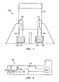
- Foot switch 100 includes a housing 102 and first and second foot activatable pedals 104 and 106, respectively, which are each pivotably coupled to housing 102 at a proximal end via a pivot pin 108.
- Each foot pedal 104 and 106 is electrically coupled to light emitting diode (LED) 110 and 112, respectively, which is, in turn electrically coupled to a power source 115.
- Each foot pedal 104 and 106 includes a foot rest 114 and 116, respectively, formed at one end thereof and each foot rest 114 and 116 has a corresponding foot pad 117 and 118 disposed on an upper surface thereof. As best shown in FIG.
- first pedal 104 includes the term "CUT"thereon and the upper surface of second pedal 106 includes the term "COAG"thereon.
- each of the terms, i. e., "CUT"and”COAG” is inscribed atop a facing surface of the respective foot pedal such that, when illuminated, a surgeon can easily and readily discern a particular pedal prior to and/or during activation.
- LED's 110 and 112 are mounted to housing 102, preferably at a point proximal to and above the foot pedals 104 and 106. In this manner, foot pedals 104 and 106 and their corresponding indicia"CUT"and”COAG"are illuminated by LED's 110 and 112 respectively. Accordingly, while performing a surgical procedure in a darkened operating room, each foot pedal 104 and 106 and the respective indicia"CUT"and”COAG" displayed thereon is illuminated such that an operator can quickly and readily identify which foot pedal 104 and 106 he/she wishes to actuate in order to perform a desired function of the electrosurgical instrument.
- LEDs 110 and 112 are illuminated prior to activation such that each pedal 104 and 106 is readily discernible. However, it is contemplated that LED 112 can also illuminate each pedal upon actuation, intensify each pedal upon actuation, blink repeatedly upon actuation or audibly sound upon actuation.
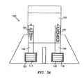
- FIG. 3A an embodiment of the foot switch 100 is shown wherein the terms"CUT"and"COAG"are formed from a plurality of LEDs 120.
- Each foot rest 114 and 116 also includes a plurality of LEDs 122 outlining pads 117 and 118.
- FIG. 3B an alternative illuminated foot switch 100 is shown in which the upper surface of foot rests 114 and 116 are each provided with the term "CUT"and”SEAL", respectively.
- the terms"CUT"and”SEAL” are formed from a plurality of LEDs 140 respectively. In this manner, when the operator looks down at the foot pedal, e. g. , 104, the foot rest identifies the feature available on the electrosurgical instrument.
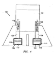
- FIG. 4 shows another embodiment of the foot switch 100 wherein the terms"CUT" and"COAG”are made up of either a translucent material (i. e. , plastic) or a transparent material (i. e. , glass or clear plastic) which glows upon illumination.
- Each foot rest 114 and 116 is provided with a channel 124 encircling pads 117 and 118 also having a translucent or transparent material disposed therein. In this manner, the light source 110, 112 illuminates both the indicia and the corresponding foot pedal 104 and 106.
- a separate light source can be disposed within each individual pedal 104 and 106 to cause the indicia"CUT"and"COAG" (as well as channel 124) to illuminate from within. Again, the operator can readily discern which pedal to depress in order to actuate the desired function of the electrosurgical instrument.
- each foot pad 117 and 118 includes a plurality of LEDs 126.
- Each foot pedal 104 and 106 is illuminated by a corresponding LED 110 and 112, respectively, mounted to housing 102 and each foot pad 117 and 118 is illuminated by LEDs 126.
- LEDs 110, 112 and 126 can be electrically coupled to an electrical switch (not shown) such that when foot pedals 104 and 106 are depressed, LEDs 110, 112 and 126 blink (see FIG. 6 ), indicating to the operator or to the operating room staff that the multi-functional instrument is activated.
- any of the above described embodiments can be provided with an electrical switch, connected between the foot pedals and the corresponding LEDs, which will cause the LEDs to blink upon actuation of a respective foot activatable pedal.
- the LEDs can be coupled to an audible switch which rings or chirps upon activation and/or deactivation of a foot pedal 104, 106.
- the LEDs are all the same color, however, it is contemplated that the LEDs may be different colors in order to aid the operator in distinguishing one foot pedal from the next.
- LED 110 can be one of either red, yellow, green, blue or white while LED 112 is another of either red, yellow, green, blue or white.
- the colors contrast one another for facile recognition among pedals. In this manner, each foot pedal 104 and 106 is illuminated in a different color thereby further differentiating foot pedal 104 from foot pedal 106.
- LEDs 120 and 122 of each foot pedal 104 and 106 can include differently colored LEDs.
- LEDs 126 which form foot pads 117 and 118, can include differently colored LEDs respectively.
- each of the above described embodiments relates to a foot-activated control switch having two foot-activatable pedals
- any number of foot-activatable pedals can be provided wherein each foot-activatable pedal actuates a different function of the electrosurgical instrument.
- all of the LEDs may be constantly illuminated, i. e. , while a foot pedal is being actuated or while the foot pedal is idle.
- LEDs can commence blinking upon activation or non-activated LEDs can go out upon the actuation of a corresponding, i. e. ,”selected,"foot pedal.
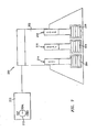
- FIG. 7 shows another of the presently disclosed illuminated foot switch 200 which includes housing 202 and a first, second and third foot pedal 204,206 and 208, respectively.
- Each pedal 204,206 and 208 is pivotably coupled to housing 202 about a proximal end and is provided with indicia"CUT","SEAL"and"COAG” inscribed thereon, respectively.
- Foot switch 200 is provided with LEDs 212,214 and 216 which are designed to illuminate a corresponding pedal 204,206 and 208, respectively.
- Each pedal 204,206 and 208 together with its corresponding LEDs 214,216 and 218 is coupled to an electrosurgical generator 210 which includes a"selector"212 for selectively setting generator 210 to either"CUT",”SEAL"or”COAG.”
- a corresponding LED 216 turns on, thus illuminating the corresponding pedal 206.
- this allows the surgeon to readily depress the corresponding pedal to activate the sealing function of an electrosurgical instrument.
- the foot switch 200 may include a screen-like display (not shown) atop the foot pedals 204,206 and 208 which illuminates and forms the particular functions selected by the surgeon, for example, the electrosurgical generator 210 may include three or four selectable functions and the foot switch may have two pedals. When the surgeon selects two functions on the generator 210, the foot switch displays/illuminates these functions. As can be appreciated, this allows the same foot switch 200 to be used with any combination of functions.
Landscapes
- Surgical Instruments (AREA)
- Switch Cases, Indication, And Locking (AREA)
- Laser Surgery Devices (AREA)
Claims (4)
- Steuersystem (100) für ein elektrochirurgisches Instrument, das Steuersystem mit:einem Gehäuse (102), das gezielt relativ zu einem Operationssaal positionierbar ist, wobei das Gehäuse mit einer elektrochirurgischen Energiequelle gekoppelt ist;wobei das Steuersystem gekennzeichnet ist durchein Paar fußaktivierbarer Pedalen (104, 106) die betriebsfähig mit dem Gehäuse in Eingriff sind, wobei eine erste des Paars fußaktivierbarer Pedalen zum Steuern einer ersten Funktion des elektrochirurgischen Instruments ist und eine zweite des Paars fußaktivierbarer Pedalen zum Steuern einer zweiten Funktion des elektrochirurgischen Instruments ist, die Pedalen jeweils Markierungen (120) aufweisen, die die Funktion des Pedals kennzeichnen, und jede der Pedalen einen Armabschnitt (104, 106) mit den Markierungen aufweist, die die Funktion des fußaktivierbaren Pedals kennzeichnen; undein Mittel (110, 112) zum Beleuchten von mindestens einem Abschnitt von jedem Pedal, um die Markierungen zu beleuchten, miteinem ersten Mittel zum Beleuchten der Markierungen des ersten fußaktivierbaren Pedals; undeinem zweiten Mittel zum Beleuchten der Markierungen des zweiten fußaktivierbaren Pedals;wobei jedes der Fußpedale an einem seiner Enden angeordnet eine Fußablage aufweist;wobei:(1) jede der Fußablagen eine Vielzahl von lichtausstrahlenden Dioden aufweist, die um ihren äußeren Umfang angeordnet sind, oder(2) die Fußablagen ein Fußpad (117, 118) aufweisen, das auf einer ihrer oberen Fläche angeordnet ist, wobei die Fußpads eine Vielzahl von lichtausstrahlenden Dioden (122) aufweisen, die an jedem der Fußpads angebracht sind, sodass jedes der Fußpads getrennt beleuchtet wird.
- Steuersystem nach einem der vorstehenden Ansprüche, bei dem das Mittel zum Beleuchten bei Betätigung von einem des ersten und zweiten fußaktivierbaren Pedals blinkt.
- Steuersystem nach einem der vorstehenden Ansprüche, bei dem das erste Mittel zum Beleuchten eine erste aus rot, gelb, grün, blau und weiß ausgewählte Farbe aufweist; und wobei das zweite Mittel zum Beleuchten eine zweite Farbe, die sich von der ersten Farbe unterscheidet und aus rot, gelb, grün, blau und weiß ausgewählt ist, aufweist.
- Steuersystem nach Alternative (2) in Anspruch 1, bei dem das erste und zweite fußaktivierbare Pedal des Weiteren jeweils eine Nut aufweisen, die das in der oberen Fläche der Fußablage ausgebildete Fußpad umgibt.
Applications Claiming Priority (3)
| Application Number | Priority Date | Filing Date | Title |
|---|---|---|---|
| US38865802P | 2002-06-11 | 2002-06-11 | |
| PCT/US2003/017126 WO2003105169A1 (en) | 2002-06-11 | 2003-05-29 | Illuminated foot-switch |
| US388658P | 2010-10-01 |
Publications (2)
| Publication Number | Publication Date |
|---|---|
| EP1512158A1 EP1512158A1 (de) | 2005-03-09 |
| EP1512158B1 true EP1512158B1 (de) | 2012-11-21 |
Family
ID=29736509
Family Applications (1)
| Application Number | Title | Priority Date | Filing Date |
|---|---|---|---|
| EP03734297A Expired - Lifetime EP1512158B1 (de) | 2002-06-11 | 2003-05-29 | Beleuchteter fussschalter |
Country Status (6)
| Country | Link |
|---|---|
| US (2) | US7259340B2 (de) |
| EP (1) | EP1512158B1 (de) |
| JP (1) | JP4391414B2 (de) |
| AU (1) | AU2003238839B2 (de) |
| CA (1) | CA2489092C (de) |
| WO (1) | WO2003105169A1 (de) |
Families Citing this family (30)
| Publication number | Priority date | Publication date | Assignee | Title |
|---|---|---|---|---|
| US7259340B2 (en) * | 2002-06-11 | 2007-08-21 | Sherwood Services Ag | Illuminated foot-switch |
| CA2803828C (en) | 2005-03-31 | 2015-11-24 | Alcon, Inc. | Footswitch operable to control a surgical system |
| US7619171B2 (en) * | 2005-06-30 | 2009-11-17 | Alcon, Inc. | Multifunction surgical footswitch |
| US8465473B2 (en) | 2007-03-28 | 2013-06-18 | Novartis Ag | Surgical footswitch with movable shroud |
| ES2593857T3 (es) * | 2008-03-13 | 2016-12-13 | Liebel-Flarsheim Company Llc | Controlador activado con el pie para sistema de formación de imágenes |
| EP2265196B9 (de) | 2008-03-31 | 2013-10-02 | Applied Medical Resources Corporation | Elektrochirurgisches System mit Mitteln zur Messung der Permittivität und der Leitfähigkeit von Gewebe |
| WO2010030788A2 (en) * | 2008-09-10 | 2010-03-18 | Mora Assad F | Foot actuated switch |
| JP5486979B2 (ja) * | 2010-03-26 | 2014-05-07 | 株式会社長田中央研究所 | 歯科治療ユニット |
| EP2898846B1 (de) | 2010-10-01 | 2018-01-31 | Applied Medical Resources Corporation | Elektrochirurgisches System mit einem Radiofrequenzverstärker und mit Mitteln zur Anpassung an den Elektrodenabstand |
| WO2014043551A1 (en) * | 2012-09-13 | 2014-03-20 | Upper King Llc | Compact modular visual effects device |
| JP6130233B2 (ja) * | 2013-06-05 | 2017-05-17 | 株式会社日立製作所 | フットスイッチ装置 |
| KR102537276B1 (ko) | 2014-05-16 | 2023-05-26 | 어플라이드 메디컬 리소시스 코포레이션 | 전기수술용 시스템 |
| JP6735272B2 (ja) | 2014-05-30 | 2020-08-05 | アプライド メディカル リソーシーズ コーポレイション | 電気外科的密封・切開システム |
| CA2968314C (en) * | 2014-11-21 | 2023-03-14 | Faculty Physicians And Surgeons Of Loma Linda University School Of Medicine | Illuminated protective covering |
| US10527277B2 (en) | 2014-11-21 | 2020-01-07 | Faculty Physicians And Surgeons Of Loma Linda University School Of Medicine | UV light illuminated surgical covering apparatus and method |
| US10060616B2 (en) * | 2014-11-21 | 2018-08-28 | Faculty Physicians And Surgeons Of Loma Linda University School Of Medicine | Illuminated protective covering for foot pedals |
| ES3014244T3 (en) | 2014-12-23 | 2025-04-21 | Applied Med Resources | Bipolar electrosurgical sealer and divider |
| USD748259S1 (en) | 2014-12-29 | 2016-01-26 | Applied Medical Resources Corporation | Electrosurgical instrument |
| US10573286B2 (en) | 2017-01-11 | 2020-02-25 | M-Wave Music Products, Llc | Music effect pedal |
| JP7443064B2 (ja) | 2017-04-28 | 2024-03-05 | ストライカー・コーポレイション | コンソールベースの外科システムのマッピングを示すシステム及び方法 |
| DE102017113393A1 (de) * | 2017-06-19 | 2018-12-20 | Fresenius Medical Care Deutschland Gmbh | Steuervorrichtung für Blutbehandlungsvorrichtung und Blutbehandlungsvorrichtung |
| EP3585462A1 (de) | 2018-01-25 | 2020-01-01 | Biogastrex LLC | Insufflationssystem |
| EP3846717B1 (de) | 2018-09-05 | 2024-12-18 | Applied Medical Resources Corporation | Steuerungssystem für elektrochirurgischen generator |
| WO2020086840A1 (en) * | 2018-10-24 | 2020-04-30 | Faculty Physicians And Surgeons Of Loma Linda University School Of Medicine | Uv light illuminated surgical covering apparatus and method |
| EP4268759B1 (de) | 2018-10-29 | 2025-01-01 | Stryker Corporation | System zur durchführung von wirbelsäulenoperationen und aufrechterhaltung eines flüssigkeitsvolumens an einer operationsstelle |
| CA3120182A1 (en) | 2018-11-16 | 2020-05-22 | Applied Medical Resources Corporation | Electrosurgical system |
| DE102019125490A1 (de) * | 2019-09-23 | 2021-03-25 | Karl Storz Se & Co. Kg | Fußschalter für medizinische Geräte |
| JP2021112434A (ja) * | 2020-01-20 | 2021-08-05 | キヤノンメディカルシステムズ株式会社 | フットスイッチ装置及びフットスイッチ装置を備えたx線診断装置 |
| CN112754644A (zh) * | 2020-12-31 | 2021-05-07 | 杭州堃博生物科技有限公司 | 一种射频消融仪的控制方法及其系统 |
| WO2025098797A1 (en) * | 2023-11-09 | 2025-05-15 | Olympus Winter & Ibe Gmbh | Electrosurgical system, electrosurgical footswitch, and method of operating the same |
Family Cites Families (34)
| Publication number | Priority date | Publication date | Assignee | Title |
|---|---|---|---|---|
| JPS6021053Y2 (ja) | 1980-12-02 | 1985-06-24 | 株式会社モリタ製作所 | 歯科治療装置用フ−トコントロ−ラ− |
| US5180925A (en) * | 1991-02-22 | 1993-01-19 | Outboard Marine Corporation | Remote switching system for an electric trolling motor |
| US5166513A (en) | 1991-05-06 | 1992-11-24 | Coherent, Inc. | Dual actuation photoelectric foot switch |
| DE9107297U1 (de) * | 1991-06-13 | 1991-08-29 | Preh-Werke GmbH & Co. KG, 97616 Bad Neustadt | Fußsteller für einen Bodenstaubsauger |
| US5712460A (en) | 1994-07-19 | 1998-01-27 | Linvatec Corporation | Multi-function surgical device control system |
| US5626575A (en) | 1995-04-28 | 1997-05-06 | Conmed Corporation | Power level control apparatus for electrosurgical generators |
| US5883615A (en) | 1995-09-29 | 1999-03-16 | Liebel-Flarsheim Company | Foot-operated control system for a multi-function |
| US5635777A (en) * | 1995-12-28 | 1997-06-03 | Andrew Telymonde | Foot operated control apparatus |
| US6179829B1 (en) | 1997-08-28 | 2001-01-30 | Bausch & Lomb Surgical, Inc. | Foot controller for microsurgical system |
| US5983749A (en) | 1997-09-12 | 1999-11-16 | Allergan Sales, Inc. | Dual position foot pedal for ophthalmic surgery apparatus |
| DE19743524C1 (de) | 1997-10-01 | 1998-10-22 | Siemens Ag | Fußschalter für medizinische Diagnostikeinrichtungen |
| US5934904A (en) | 1997-10-14 | 1999-08-10 | Kreativ, Inc. | Dental instrument and processes |
| US5863112A (en) * | 1998-04-23 | 1999-01-26 | Didato; Thomas | Emergency brake illuminator |
| JP3644258B2 (ja) * | 1998-06-25 | 2005-04-27 | オムロン株式会社 | スイッチ |
| US6508801B1 (en) * | 1998-08-27 | 2003-01-21 | S. Lee Fineberg | Method, composition and apparatus for rapid and accurate pediatric resuscitation and emergency medical treatment |
| US6176853B1 (en) | 1998-11-05 | 2001-01-23 | Scieran Technologies, Inc. | Foot switch to proportionally control a medical cutting device |
| GB2350722B (en) * | 1999-05-29 | 2002-10-02 | Gamesman Ltd | Improvements relating to push button switch assemblies |
| US6452123B1 (en) | 2000-06-27 | 2002-09-17 | Advanced Medical Optics | Surgical foot pedal control including ribbon switch arrangement |
| JP4359381B2 (ja) | 2000-06-30 | 2009-11-04 | 株式会社ニデック | 眼科用装置 |
| BR0113825A (pt) | 2000-10-17 | 2003-06-03 | Alcon Inc | Sistema de microcirurgia, método para mapear funções cirúrgicas de um sistema de microcirurgia |
| DE10057589C1 (de) | 2000-11-21 | 2002-07-11 | Erbe Elektromedizin | Fußschalter |
| DE10114333B4 (de) | 2001-03-23 | 2006-02-16 | Ferton Holding S.A. | Fußschalter |
| US6894236B2 (en) * | 2001-05-25 | 2005-05-17 | James L. Chappuis | Universal surgical power tool foot pedal apparatus |
| US7012203B2 (en) | 2001-09-07 | 2006-03-14 | Carl Zeiss Surgical Gmbh | Foot switch pedal controller for a surgical instrument |
| US6674030B2 (en) | 2001-09-19 | 2004-01-06 | Advanced Medical Optics | Intelligent surgical footpedal with low noise, low resistance vibration feedback |
| US7470277B2 (en) | 2001-10-16 | 2008-12-30 | Alcon, Inc. | Simultaneous proportional control of surgical parameters in a microsurgical system |
| US6639332B2 (en) | 2001-12-19 | 2003-10-28 | Bausch & Lomb Incorporated | Foot controller with ophthalmic surgery interlock circuit and method |
| US6689975B2 (en) | 2001-12-19 | 2004-02-10 | Bausch & Lomb Incorporated | Foot controller including multiple switch arrangement with heel operated, door-type switch actuator |
| US7259340B2 (en) * | 2002-06-11 | 2007-08-21 | Sherwood Services Ag | Illuminated foot-switch |
| US6962581B2 (en) | 2002-12-03 | 2005-11-08 | Alcon, Inc. | Foot controller for microsurgical system |
| CA2543613A1 (en) | 2003-10-28 | 2005-05-12 | Uab Research Foundation | Electrosurgical control system |
| US7122751B1 (en) * | 2004-01-16 | 2006-10-17 | Cobalt Flux | Switch apparatus |
| US7094231B1 (en) | 2004-01-22 | 2006-08-22 | Ellman Alan G | Dual-mode electrosurgical instrument |
| US6969811B1 (en) * | 2004-08-31 | 2005-11-29 | Li-Chun Lai | Foot switch structure of extension cord receptacle |
-
2003
- 2003-05-29 US US10/516,865 patent/US7259340B2/en not_active Expired - Lifetime
- 2003-05-29 JP JP2004512152A patent/JP4391414B2/ja not_active Expired - Fee Related
- 2003-05-29 WO PCT/US2003/017126 patent/WO2003105169A1/en not_active Ceased
- 2003-05-29 EP EP03734297A patent/EP1512158B1/de not_active Expired - Lifetime
- 2003-05-29 CA CA2489092A patent/CA2489092C/en not_active Expired - Fee Related
- 2003-05-29 AU AU2003238839A patent/AU2003238839B2/en not_active Ceased
-
2007
- 2007-05-30 US US11/807,634 patent/US7557317B2/en not_active Expired - Fee Related
Also Published As
| Publication number | Publication date |
|---|---|
| EP1512158A1 (de) | 2005-03-09 |
| JP2005529659A (ja) | 2005-10-06 |
| US7259340B2 (en) | 2007-08-21 |
| CA2489092C (en) | 2012-07-24 |
| US7557317B2 (en) | 2009-07-07 |
| US20070227868A1 (en) | 2007-10-04 |
| CA2489092A1 (en) | 2003-12-18 |
| WO2003105169A1 (en) | 2003-12-18 |
| US20060090990A1 (en) | 2006-05-04 |
| AU2003238839A1 (en) | 2003-12-22 |
| JP4391414B2 (ja) | 2009-12-24 |
| AU2003238839B2 (en) | 2008-04-03 |
Similar Documents
| Publication | Publication Date | Title |
|---|---|---|
| US7557317B2 (en) | Illuminated foot-switch | |
| US20230390005A1 (en) | System and method for indicating mapping of console-based surgical systems | |
| EP1478878B1 (de) | Ergonomische steuerungen eines chirurgischen beleuchtungssystems | |
| US20090012516A1 (en) | Electrosurgical system | |
| US8465473B2 (en) | Surgical footswitch with movable shroud | |
| US20100268221A1 (en) | Signal device for electrosurgical instruments, adaptor for connecting an electrosurgical instrument | |
| US20150076211A1 (en) | Surgical instrument controls with illuminated feedback | |
| US20080312649A1 (en) | Illuminated instrument buttons | |
| US11759187B2 (en) | Footswitch for medical devices | |
| JPH06197932A (ja) | 人間または動物の医療処理装置用制御装置 | |
| US20060170700A1 (en) | Control interface |
Legal Events
| Date | Code | Title | Description |
|---|---|---|---|
| PUAI | Public reference made under article 153(3) epc to a published international application that has entered the european phase |
Free format text: ORIGINAL CODE: 0009012 |
|
| 17P | Request for examination filed |
Effective date: 20041210 |
|
| AK | Designated contracting states |
Kind code of ref document: A1 Designated state(s): AT BE BG CH CY CZ DE DK EE ES FI FR GB GR HU IE IT LI LU MC NL PT RO SE SI SK TR |
|
| AX | Request for extension of the european patent |
Extension state: AL LT LV MK |
|
| RAP1 | Party data changed (applicant data changed or rights of an application transferred) |
Owner name: SHERWOOD SERVICES AG |
|
| DAX | Request for extension of the european patent (deleted) | ||
| RBV | Designated contracting states (corrected) |
Designated state(s): DE ES FR GB IE IT |
|
| RAP1 | Party data changed (applicant data changed or rights of an application transferred) |
Owner name: COVIDIEN AG |
|
| 17Q | First examination report despatched |
Effective date: 20101112 |
|
| GRAP | Despatch of communication of intention to grant a patent |
Free format text: ORIGINAL CODE: EPIDOSNIGR1 |
|
| GRAS | Grant fee paid |
Free format text: ORIGINAL CODE: EPIDOSNIGR3 |
|
| GRAA | (expected) grant |
Free format text: ORIGINAL CODE: 0009210 |
|
| AK | Designated contracting states |
Kind code of ref document: B1 Designated state(s): DE ES FR GB IE IT |
|
| REG | Reference to a national code |
Ref country code: GB Ref legal event code: FG4D |
|
| REG | Reference to a national code |
Ref country code: IE Ref legal event code: FG4D |
|
| REG | Reference to a national code |
Ref country code: DE Ref legal event code: R096 Ref document number: 60342649 Country of ref document: DE Effective date: 20130117 |
|
| PG25 | Lapsed in a contracting state [announced via postgrant information from national office to epo] |
Ref country code: ES Free format text: LAPSE BECAUSE OF FAILURE TO SUBMIT A TRANSLATION OF THE DESCRIPTION OR TO PAY THE FEE WITHIN THE PRESCRIBED TIME-LIMIT Effective date: 20130304 |
|
| PG25 | Lapsed in a contracting state [announced via postgrant information from national office to epo] |
Ref country code: IT Free format text: LAPSE BECAUSE OF FAILURE TO SUBMIT A TRANSLATION OF THE DESCRIPTION OR TO PAY THE FEE WITHIN THE PRESCRIBED TIME-LIMIT Effective date: 20121121 |
|
| PLBE | No opposition filed within time limit |
Free format text: ORIGINAL CODE: 0009261 |
|
| STAA | Information on the status of an ep patent application or granted ep patent |
Free format text: STATUS: NO OPPOSITION FILED WITHIN TIME LIMIT |
|
| 26N | No opposition filed |
Effective date: 20130822 |
|
| REG | Reference to a national code |
Ref country code: DE Ref legal event code: R097 Ref document number: 60342649 Country of ref document: DE Effective date: 20130822 |
|
| PGFP | Annual fee paid to national office [announced via postgrant information from national office to epo] |
Ref country code: IE Payment date: 20140527 Year of fee payment: 12 Ref country code: GB Payment date: 20140527 Year of fee payment: 12 |
|
| PGFP | Annual fee paid to national office [announced via postgrant information from national office to epo] |
Ref country code: DE Payment date: 20140529 Year of fee payment: 12 Ref country code: FR Payment date: 20140519 Year of fee payment: 12 |
|
| REG | Reference to a national code |
Ref country code: DE Ref legal event code: R119 Ref document number: 60342649 Country of ref document: DE |
|
| GBPC | Gb: european patent ceased through non-payment of renewal fee |
Effective date: 20150529 |
|
| REG | Reference to a national code |
Ref country code: IE Ref legal event code: MM4A |
|
| REG | Reference to a national code |
Ref country code: FR Ref legal event code: ST Effective date: 20160129 |
|
| PG25 | Lapsed in a contracting state [announced via postgrant information from national office to epo] |
Ref country code: GB Free format text: LAPSE BECAUSE OF NON-PAYMENT OF DUE FEES Effective date: 20150529 Ref country code: DE Free format text: LAPSE BECAUSE OF NON-PAYMENT OF DUE FEES Effective date: 20151201 Ref country code: IE Free format text: LAPSE BECAUSE OF NON-PAYMENT OF DUE FEES Effective date: 20150529 |
|
| PG25 | Lapsed in a contracting state [announced via postgrant information from national office to epo] |
Ref country code: FR Free format text: LAPSE BECAUSE OF NON-PAYMENT OF DUE FEES Effective date: 20150601 |