EP1511906B1 - Element de construction en bois et jeu d'elements pour la construction de murs de batiments a l'aide d'elements de construction en bois - Google Patents
Element de construction en bois et jeu d'elements pour la construction de murs de batiments a l'aide d'elements de construction en bois Download PDFInfo
- Publication number
- EP1511906B1 EP1511906B1 EP03755898A EP03755898A EP1511906B1 EP 1511906 B1 EP1511906 B1 EP 1511906B1 EP 03755898 A EP03755898 A EP 03755898A EP 03755898 A EP03755898 A EP 03755898A EP 1511906 B1 EP1511906 B1 EP 1511906B1
- Authority
- EP
- European Patent Office
- Prior art keywords
- exterior
- plates
- edges
- plate
- horizontal
- Prior art date
- Legal status (The legal status is an assumption and is not a legal conclusion. Google has not performed a legal analysis and makes no representation as to the accuracy of the status listed.)
- Expired - Lifetime
Links
Images


Classifications
-
- E—FIXED CONSTRUCTIONS
- E04—BUILDING
- E04C—STRUCTURAL ELEMENTS; BUILDING MATERIALS
- E04C2/00—Building elements of relatively thin form for the construction of parts of buildings, e.g. sheet materials, slabs, or panels
- E04C2/30—Building elements of relatively thin form for the construction of parts of buildings, e.g. sheet materials, slabs, or panels characterised by the shape or structure
- E04C2/34—Building elements of relatively thin form for the construction of parts of buildings, e.g. sheet materials, slabs, or panels characterised by the shape or structure composed of two or more spaced sheet-like parts
Definitions
- the invention relates to a timber component for producing planar structures, in particular for the construction of erected building walls, with approximately the same rectangular, approximately parallel plates, which are kept separate from each other by intermediate elements including rod-like elongated supports and cover a subdivided into chambers cavity between them which supports with respect to their rod length to each other and to the side edges of the plates approximately parallel and longitudinal edges of the plates are approximately vertically aligned and spaced apart in the cavity, and provided with means for forming positive connections between abutting longitudinal sides of adjacent, intended upright superimposed wooden components with vertically aligned plate surfaces and Hochstimfact.
- Wood construction elements of the type mentioned are available on the market and have also become known, for example, from EP 0 744 507 A and WO 97 39 204 A.
- the known timber construction elements can only be used for limited applications and do not meet particularly high demands on stability, thermal insulation, moisture insulation, durability against bacterial and other microbiological attacks and weather, simplicity and reliability of manufacture and handling, and design and appearance of finished structures.
- a building juxtaposed timber components according to the prior art can not otherwise form-fit with each other form as by means of above or below offset longitudinally arranged timber components. Lack of immediate connection to lateral joints between the timber components neither stability nor insulation are readily ensured.
- WO 02 25 029 A component for use in skeleton constructions of building walls mainly made of wood or wood-based materials has become known.
- This device has three rod-like elongated supports with a substantially rectilinear Center profile of elongated support walls and with laterally adjacent edge profiles of elongated edge sides.
- the columns are to be aligned vertically with respect to their length of the structure and to be arranged at equal distances from each other with a certain spacing.
- cross bars which keep the supports in a row approximately parallel to each other and at equal distances from each other and protrude laterally beyond the row of supports so far that they equal outstanding transverse rods abutting the same adjacent components terminal supports of a component of terminal supports of the adjacent components with equal distances of the particular Rastemnenses keep away.
- Such a cross bar may consist of a rectangular board, which is connected flush with each one of the edge sides of the three supports. With such components supporting frameworks can be constructed in the manner of truss, which is then filled with sealing material and boarded with boards.
- the serving as a cross bar on the board can form on the finished structure first, one-sided shuttering of the bearing truss formed by the supports.
- One of the first, one-sided shuttering opposite second formwork on the other side of the supporting framework can be attached to the building only after filling the truss with sealing material.
- the length of the columns and the vertical extent of the structure of the vertical edges of serving as a cross bar and formwork board is about the same.
- the supports are arranged vertically offset relative to the board on the building so that on the one hand protrude the upper ends of the supports on the upper longitudinal edge of the board and on the other hand along the lower edge of the board on the inside of a non-divided by columns remains, free edge strip remains on which the free upper ends of supports of a below adjacent same component can lean.
- the cohesion of these components is achieved at least temporarily on the building. Thereafter, a further solidification of the structure by placing a board opposite the second formwork is required.
- a wooden construction element for building erected building walls which essentially comprises two mutually parallel wall stacks of wood and transversely arranged spacers in the form of transverse webs without additional supporting function.
- Each of these wall stacks has sole supporting function and consists essentially of a support plate in the form of a thicker pile of boards and from a thinner wall plate in the form of a facade panel attached to the outside of the support plate.
- the support plates and the wall plates have approximately the same plate surfaces and the wall plates are arranged diagonally offset from the support plates such that there are two perpendicular abutting Patritzen- or spring profiles and rectangular abutting Matritzen- or groove profiles as in the wall element according to the invention.
- An overlap of support plates and wall panels of adjacent components should serve to seal the space between the wall stacks as completely as possible.
- a supporting structure of columns is not provided. Rather, the greatest possible accessibility of the space between the wall stacks is sought so that insulation material can be easily introduced by pouring or blowing.
- building walls of wood components with wall stacks of the known type without supporting scaffold withstand only very low loads.
- the invention is based on the technical object to overcome the difficulties encountered in the prior art.
- the achievement of this object is essentially to recognize in a timber component with the features indicated in the attached claim 1.
- the supports substantially rectilinear center profile and laterally adjacent edge profiles of elongated edge sides have to be directly fixedly connected at their edge sides with approximately the same rectangular, approximately parallel to each other aligned support plates between form the support plates approximately at right angles to aligned support walls with flat surfaces that divide the cavity between the support plates in chambers, have a length approximately equal to the edges of the support plates and end faces end faces that terminate flush with limited by longitudinal edges of the support plates Lssensstim lake.
- dovetail profiles having approximately diametrically opposed grooves, preferably corresponding dovetail grooves engage the inner surfaces of the support plates and thus form a simple form-fitting tongue and groove connection or a double positive dovetail connection.
- the plate surfaces are approximately equal to the plate surfaces of the support plates or slightly smaller, each of two longitudinal edges limited longitudinal end surfaces and limited by two edges Hochstim vom the wall plates approximately parallel to the longitudinal edges bounded by longitudinal edges and surfaces of High edges limited high end faces of the support plates are aligned.
- the wall panels are to be arranged offset to the support plates in directions of the longitudinal edges and the edges, with opposite, over longitudinal faces of the support plates protruding longitudinal edges of the wall panels and opposite, over edges and delimiting high end faces of the support plates protruding High edges of the wall panels form the flanks of two approximately perpendicular to each other to Matrizen- or groove profiles and where longitudinal edges and edges of the support plates on the one hand and by remote longitudinal edges and edges of the wall panels on the other hand limited exposed longitudinal edges and high edges of the support plates, the flanks of two approximately at right angles to each other directed Patrizen- or spring profiles approximately reverse equal to form the die or groove profiles.
- wood components according to the invention can be similar to the known wood components according to DE 101 10 798 A1.
- a particular advantage of the timber component according to the invention with supporting columns in solid composite with load-bearing walls compared with the known prior art is considerably increased stability, durability and freedom of design finished structures despite relatively little effort.
- the claim 2 dimensions which have proven particularly useful in practice.
- the essential features of the embodiment of the timber component according to the invention are given as a corner element for the connection of corners meeting one another wall parts.
- the claims 4 and 5 relate to features advantageous material design of support plates and columns.
- the claims 6 to 10 contain the information on timber construction apparently completely new combinations of features for the purpose of generating inventively recognized as advantageous conditions concerning the vapor diffusion to building walls of timber construction elements.
- claims 6 to 10 relate to the inventive features of particularly advantageous means for connecting timber components of the type according to one of claims 1 to 10 in a building.
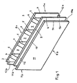
- the wooden construction element according to FIGS. 1 to 6 has a rectangular inner support plate 1 and an approximately coextensive outer support plate 2.
- Four identical, rod-like elongated profile cylindrical shaped supports 5 have a profile with approximately rectangular cross-section and have flat, elongated rectangular edge sides, which are firmly connected to the abutting support plates 1, 2. It comes a spring and groove connection or a dovetail connection between supports and support plates are used. The details of such a connection can be seen in FIGS. 7 to 10.
- the four supports 5 of the timber component according to Figures 1 to 6 are arranged in a row in the direction along the support plates 1, 2 with equal distances of a certain pitch from each other. They extend approximately perpendicular to Leksstim lake 3 between longitudinal edges 3 of the support plates 1, 2 and approximately parallel to lateral high end faces 4 between the vertical edges 4 of the support plates 1, 2 and have at their ends in each case a Endstim configuration 6.
- the length of the support plates between their lateral edges or Hochstim lake 4 is four times the said grid and the two outer columns in the said series are each removed by half a grid from the edges or Hochstim lake.
- the supports 5 have a length approximately equal to the width or height of the support plates. Their end faces 6 are flush with the adjacent longitudinal end faces 3 of the support plates.
- the supports are arranged at equal intervals of a certain grid distance from each other.
- a grid size of the size between 150 mm and 350 mm, preferably a pitch of 250 mm has proven particularly useful.
- the first and the last support in the row of the support plates 1, 2 arranged between the supports 5 have distances from the nearest lateral edges 4 of the support plates, which complement each other to full pitch. Under these circumstances, vertical loads are uniformly absorbed by the vertically oriented support plates 1, 2 and supports 5 and derived on foundations when wood components according to the invention of Figure 1, properly upright and above each other in a building are connected together and if so superposed columns vertically aligned with each other and lower on upper end faces 6 abut.
- Elongated rectangular surfaces of the supports 5 and the inner surfaces of the support plates 1, 2 divide the cavity between the support plates in elongated cuboid chambers 7 and laterally in two Halbkammem, which together with the same Hatbkarnmern laterally adjacent timber construction elements in a composite complete chambers equal to the Chambers 7 are determined to form.
- the chambers 7 in a structure of superimposed components as well as the supports abut each other vertically aligned and are easily accessible from above. They can be filled with heat-insulating material, in particular in the form of foams, fibers, flakes, chips, granules or the like, preferably with rockwool. Cloth, foil or other sheet material may be used to seal the filled chambers.
- the right high side 9a of a timber component and the left high side 9b of another wood component subsequently arranged in the same row meet as intended.
- the upper longitudinal side 8a of a lower timber component abut on the lower longitudinal side 8b of a subsequently arranged in an upper row wooden construction element.
- the timber construction elements according to the invention can be arranged one above the other with aligned high-end faces 9a, 9b or offset in the longitudinal direction relative to one another when the lengths of the support plates 1, 2 and the distances between the supports 5 have uniform locking dimensions.
- an inner wall plate 11 and on the outer surface of the outer support plate 2, an outer wall plate 12 is attached on the outer surface of the inner support plate 1.
- the surfaces of the wall panels are approximately equal to or slightly smaller in outer dimensions than the surfaces of the support panels.
- the wall plate 11 has an approximately same protruding longitudinal edge 11a or an approximately same protruding high edge 11b on.
- the inner wall plate 11 covers the inner support plate 1 except for a free longitudinal edge 1a and a free high edge 1 b.
- An approximately same free permanent longitudinal edge or an approximately same free permanent high edge are located on the not visible in Figure 1 outer surface of the outer support plate 11.
- the wall plates 11, 12 are thus offset in the two directions of longitudinal edges and edges on the support plates. 1 , 2 arranged.
- the free longitudinal edges and high edges on the support plates are thus about the same width as, or slightly wider than the longitudinal edges or edges of the same support plates protruding longitudinal edges or high edges of the wall panels.
- the longitudinal edges and high edges of the support plates protruding longitudinal edges and high edges of the wall panels form the lateral edges of two approximately at right angles to each other directed groove profiles fit into the spring profiles formed by the free longitudinal edges or high edges of the support plates flanks. Wooden components with the same tongue and groove profiles can therefore be placed side by side and, when placed upright, one above the other.
- the bearing parts made of natural wood or processed wood material should be arranged according to the invention as possible with standing Holzfasem such that, for example, the Holzfasem are aligned in the support plates approximately parallel to their edges and in the supports of Endstim settings Endstim configuration.
- support plates are advantageous Rauhspundbretter with standing fibers, as supports advantageous standing timber used.
- the wall panels 11, 12 are not intended primarily for receiving vertical loads but for protection against influences normal to their surfaces and / or otherwise for active or passive environmental design. According to their aesthetic and technical purpose accordingly, the wall panels may be designed differently from the support panels in terms of material and structure. If the wall panels are slightly smaller than the support plates, joints between Llvesstim vom and Hochstim lake of wall panels on top of each other and juxtaposed timber components arise in the composite of a building. Such joints can according to the invention for venting cavities between the support plate and attached wall plate as shown for example in Figure 13 and / or for receiving rubber-elastic sealing strands as shown for example in Figure 12 and / or serve for receiving plastic sealing material or installation or decorative material.
- the wall panels defining an inner side and an outer side of the timber component with their outer surfaces may also be different according to the invention in terms of material, structure, quality and appearance.
- the intended purpose in the composite of a building an interior facing wall plate may have the outer surface of a viewing wall, for example, meets the requirements of the industry You can also for attachment of domestic installations and of a example with Kontertattung arranged wall of plaster and cardboard in the composite or the like Wall material be particularly suitable and made of a material that affects the climate of an interior advantageous.
- the intended in the composite of a building an outdoor space or the environment facing wall plate can be inventively designed so that it protects against harmful weather conditions such as sun, rain and snow and wind itself and serves as an outer wall or for attaching an additional protective layer, for example, for fixing lime plaster or shingles or the like.
- a wall composed of wood components according to the invention is intended to separate an interior space from an exterior space, that the interior encloses sources of humidity such as humans and animals breathing and that the outdoor space tends to dissipate moisture despite adverse weather conditions.
- sources of humidity such as humans and animals breathing
- outdoor space tends to dissipate moisture despite adverse weather conditions.
- Such conditions usually exist on the outer walls of buildings for living and works.
- a wood component intended for the formation of such walls is diffusion-tight on its inside rather than on its outside, that is, a vapor barrier exists in the composite of inner support plate 1 and inner wall plate 11 which prevents diffusion protects moisture from the interior of a building in the divided into chambers 7 cavity of the timber component and that in the composite of outer support plate 2 and outer wall plate 12, the diffusion of moisture from said cavity is promoted in an outdoor space or in the environment.
- an effective vapor barrier in a diffusion-proof glue layer exist that connects the two plates together.
- the composite of outer support plate 2 with outer wall plate 12 of Figure 1 contains no special diffusion barrier layer but according to the invention for gas and vapor permeable components.
- the vapor barrier layer between inner support plate 1 and inner wall plate 11 is not only in a diffusion-tight glue layer 15 but additionally in a vapor barrier plate or foil 16, preferably in English as "Oriented Strand Board" or abbreviated OSB Plate is called rigid plate.
- the outer support plate 2 has slits 17 which are aligned with their longitudinal edges 3 and parallel to their edges 4, preferably in the form of two saw cuts in the region of each chamber 7. These slots do not affect the required stability of the support plate if and as far as they do not cross cut across wood fibers of the plate. On the other hand, they are permeable to gases and vapors and serve to vent the chambers 7 and the insulating material located therein.
- the outer wall plate 12 connected to the outer support plate in the area above the slots on a cavity which is shown in Figures 4 and 6 as a rectangular opening 18 but also as shown in Figure 13 to be covered and a hidden, permeable to gases and vapors connection to the outside may have.
- a weatherproof covering of the slots 17 in the region of the opening 18 in a directed partially permeable Dämmschutz für 19 preferably in the form of a layer material or vapor release material, which is impermeable on the one hand impermeable to water but on the other hand permeable to vapor and tear.
- Dämmschutz füren are known in the construction industry.
- Dämmschutz für is attached at least along its edge to the outer surface of the outer support plate by gluing and / or pressing by means of the overlying wall plate and / or by means of nails, Klammem or the like.
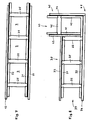
- Figure 7 of the drawings shows a wooden construction element of the type according to Figures 1 to 6 with support plates 21 and 22 and with supports 25.
- the supports have at their edges dovetail profiles, the support plates correspondingly shaped dovetail grooves, in which the dovetail profiles of the supports are inserted. So there is a multiple positive connection between columns and support plates.
- the same parts are shown in Figure 7 as in Figures 1 to 6 with the same reference numerals.
- the wood construction element according to the invention according to FIG. 8 is intended for joining wall parts which meet one another in corners and consists essentially of two limbs of different length, which meet at right angles in a corner.
- a longer leg 30 has a series of three supports 35, an inner support plate 31, an outer support plate 32, an inner wall plate 33 and an outer wall plate 34, which are basically connected to each other as well as the supports, support plates and wall panels of the timber component of FIG 7.
- a shorter leg 40 consists mainly in a support 45, an inner support plate 41, an outer support plate 42, an inner wall plate 43 and an outer wall plate 44, the connection of which also corresponds to the connection of corresponding plates and supports of Figure 7.
- the row of the three pillars 35 is oriented approximately perpendicular to the support and wall plates of the shorter leg 40 or perpendicular to a virtual series of pillars 45 of the shorter leg 40, which virtual row with more than one pillar in the direction perpendicular to the transverse extension of the pillar 45 can be realized from edge to edge profile.
- the inner support plate 31 and inner wall plate 33 of the longer leg 30 terminate immediately adjacent to a last post 35 in the longer leg row on the outer surface of the inner wall plate 43 of the shorter leg 40.
- the outer support plate 32 and outer wall plate 34 of the longer one Legs 30 extend beyond a high side of the shorter leg 40 to an outer corner 48 where they meet the outer support plate 42 and the outer wall plate 44 of the shorter leg 40, respectively.
- the inner support plate 41 and the inner wall plate 43 of the outer leg 40 terminate on the inner surface of the outer support plate 32 immediately adjacent to the last support 35 of the longer leg 30 in the row.
- the longer leg 30 has an open end 39 with protruding high edges of the wall panels 33, 34 and the shorter legs 40 an open end 49 with free high edges of the support plates 41, 42. At these open ends corresponding timber components of the type shown in Figure 7 can be inserted.
- a complete kit for the construction of buildings with multiple corners, however, according to the invention contains even more wood components for the formation of corners, their longer legs at their open ends as the shorter leg 40 of Figure 8 and their shorter legs at their open ends as the longer leg after Figure 8 are formed.
- a complete kit can also contain wooden components for forming corners, the legs of which each have a row of supports extended or shortened by one or two supports and a corresponding one Have increased or decreased length, and make it possible to arrange stacked wooden components offset from each other.
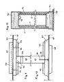
- FIGS. 9 and 10 show in particular details of two embodiments of the support plates, columns and wall panels of wood components according to the invention.
- a support 55 of the type shown in FIGS. 7 and 8 with dovetail profiles is inserted on its edge sides into a dovetail groove 56 of a support plate which according to the invention consists of a base plate 51 and plate parts 52 stacked above it. In each case, two plate parts 52 form the mutually opposite side flanks of the dovetail groove 56.
- FIG. 9 also shows an insulating protective layer 57 and a wall plate 58.
- the wall plate has an inner cavity 59 which conceals slots 54 in the support plate 51, 52 and is hidden from the environment in a compound permeable to gases and vapors.
- In at least one of the end faces of the support 55 is a depression, preferably a semi-circular cross-section milled recess 53 for receiving in wall structures approximately horizontally extending supply lines for water, gas, electricity and the like.
- the embodiment of the wood construction element according to the invention according to FIG. 10 has a support 65 with rectangular edge profiles, which are stuck in the same way in grooves of the type of a groove 66.
- the groove 66 is formed between side edges of plate members 62, which are layered together with a base plate 61 to a multi-part support plate.
- a schematically illustrated nail 64 indicates that the support 65 may be secured to the support plate 61, 62 by a row of such nails extending perpendicular to the plane of the page.
- the support 65 may still be glued to the support plate 61, 62.
- a vapor barrier layer 67 and a wall plate 68 should cover the nail heads.
- An inventive kit for the construction of structures has string-like foundations, preferably threshold timbers, and string-shaped cornices, preferably Simshölzer on.
- the threshold timber or Sims woods may be made of glulam, for example.
- Figure 11 of the drawings shows the cross-section of a threshold timber 71 and a sycamore 72 in schematic connection with the support plates 1 and 2 and with the wall plates 11 and 12 of a timber component according to Figures 1 to 6.
- the threshold wood 71 rests on a mortar bed or strip foundation 70 firm ground and has the profile of a male or spring, which engages in the groove on the lower longitudinal end face of a timber component and the support plates 1, 2 at whose lower Lijnsstim lake supported.
- the timber has the profile of a die or groove, which is slipped over exposed longitudinal edges of the support plates 1, 2 at the upper longitudinal end side of the timber component.
- threshold timber and timber mainly vertical forces and opposing forces are introduced into the wooden construction elements. They also serve, to a limited extent, to absorb shear forces and localize the timber components.
- a milled recess 73 at the upper edge of support walls serves to receive horizontally extending supply lines.
- a longitudinal stop surface 81 of support plates of a lower timber component is intended to abut a respective longitudinal longitudinal surface 82 of support plates of an upper timber component in the assembly of an upright structure.
- Longitudinal end faces 83 and 84 of wall plates of the lower and / or upper timber component fastened on the support plates are likewise intended to lie opposite one another.
- a sealing groove preferably in the form of a round groove 86, into which a preferably round, rubber-elastic sealing strip 85 is inserted, is located in the longitudinal stop face 81.
- the opposite Leksstim preparation 82 has a flatter sealing groove with a larger overall cross-section, preferably a circular segment-shaped sealing groove 87, in which a protruding from the circular groove 86 part of the sealing strip 85 takes place when it is squeezed in the abutment of Leksstim vom 81 and 82.
- a rubber-elastic sealing strip may be preferably inserted a flat sealing strip 89 which fills a gap between the Leksstimftownen the wall panels.
- the round groove 86 and the sealing groove 87 as well as the sealing strip 85 and the Didtunsband 89 may be continued on a respective Hochstim simulation the support plate or wall plate and there serve to seal edgewise butt joints between juxtaposed timber components.
- a latch 90 connects an upper support wall 91 of the uprights of an upper timber member to a lower support wall 92 of the pillars of a lower timber member on which the upper timber member is mounted.
- the support walls abut against each other at the butt joint 93.
- the thrust walls of the two supports of the timber components adjacent to the high-step surfaces 4, 14 are mainly interconnected by bolts.
- the bars are located on the Hochstim lake facing outer surfaces of the supporting walls, which are accessible to tools. .
- 14 adjacent first and last support are located approximately centrally between the edge sides of the supports each at least two arranged in series screw holes preferably in the form of holes with threaded sleeves for machine screws.
- 14 shows an upper screw hole 94 with inserted threaded sleeve 95 in the upper support wall 91 and a lower screw hole 97 with inserted threaded sleeve 98 in the lower support wall 92.
- the threaded sleeves each end in perforated plates 96 and 99, each on an inner surface the support walls 91 and 92 are nailed to the back of the bolt 90.
- FIGS. 15 to 18 the lower end of the bolt 90 and the washer 105 are shown on an enlarged scale.
- the bar In the region of the closed end of the slot 104, the bar has on its surface a milled-in groove 107 of shallow depth up to about 3 mm.
- the disc hole 106 In this Quemut fits the rectangular washer 105, the disc hole 106 should be disposed above the slot 104 such that the shaft of the screw 102 can be inserted through and screwed into the threaded sleeve 98.
- the transverse groove 107 forms at the end facing the bolt end a collision edge 108 which is a thrust edge of the washer 105
- the screw 102 is only partially screwed into the threaded sleeve 98 and enough space between the screw head and the outer surface of the support wall 92 remains, the Latch be inserted from above between the washer on the one hand and the outer surface of the support wall.
- the washer locks the bolt 90 positively against any tensile force towards the upper end of the bolt.
- the washer thus acts together with the transverse groove as a locking disc.
- the latch 90 has the same dovetail profile throughout its length. He is as shown in Figures 13 and 14 in depressions with equivalent effective cross-sectional profile, namely inserted into dovetail grooves 111 and 112 on the outer surfaces of the upper support wall 91 and the lower support wall 92 and so locks the adjacent timber elements against shear forces, the could otherwise lead to dislocations in the direction of the L Lucassstimfact.
- the introduction of the bolt into the dovetail grooves 111 and 112 open to the end faces 6 is facilitated by tapering at least one of the lower ends of the bolt 90 shown in FIGS. 14 and 15, in which the slot 104 is located.
- a taper in the thickness of the locking end is shown in Figure 14, a taper of the lateral dimensions in Figure 15 can be seen.
- the fastening foot 120 shown in FIGS. 19 and 20 serves for anchoring wooden components of the bottom row of a wall structure in the ground.
- the mounting foot is substantially in the form of an elbow 121 having a bottom plate 122 for mounting on a floor sill 126 by means of bolts or ground dowels and a support plate 123 for attachment to the support wall of supports 5.
- the support plate 123 can basically be attached directly to a support wall by screws.
- a connecting piece 125 in the form of a bar with a dovetail-shaped cross section is fastened by riveting, screwing or welding.
- This connecting piece can be inserted into one of the dovetail grooves 111 and 112 provided in the outer surface of retaining walls 91 and 92, respectively, for receiving bolts, and there in the manner shown in FIGS. 13 to 18 as a bolt with the corresponding one Support wall to be bolted.
- the bottom plate 122 are screw holes in the form of holes 124 for receiving wood screws or ground dowels that connect to the ground, in particular sleepers 126 produce.
- the thresholds may take the form of threshold beams 71 on which the bottom plate is to be secured by wood screws.
Landscapes
- Engineering & Computer Science (AREA)
- Architecture (AREA)
- Civil Engineering (AREA)
- Structural Engineering (AREA)
- Load-Bearing And Curtain Walls (AREA)
- Finishing Walls (AREA)
- Panels For Use In Building Construction (AREA)
- Rod-Shaped Construction Members (AREA)
- Building Environments (AREA)
Claims (15)
- Élément de construction en bois destiné à la fabrication d'édifices de grande étendue, notamment à la construction de murs de bâtiments verticaux, avec des plaques (1, 2, 11, 12 ; 21, 22 ; 31-34 ; 41-44 ; 51, 52, 58 ; 61, 62 ; 58, 68) rectangulaires de surface sensiblement identique et disposées sensiblement parallèlement les unes aux autres, maintenues séparément les unes des autres par des éléments intermédiaires et recouvrant entre elles un espace creux, lesquels éléments intermédiaires présentent de longs contreforts semblables à des barres (5, 25, 35, 45, 55, 65, 91, 92) qui, relativement à leur longueur, sont orientés sensiblement parallèlement les uns aux autres ainsi que par rapport aux bords hauts latéraux (4) des plaques et sensiblement verticalement par rapport aux bords longs (3) de ces plaques, et répartis au sein de l'espace creux à un certain intervalle les uns des autres, et avec des systèmes de formation de connexions mécaniques entre les côtés frontaux longs (8a, 8b), retombant l'un sur l'autre, des éléments de bois voisins, ordonnés verticalement les uns sur les autres conformément à l'usage, avec les faces des plaques ainsi que les côtés frontaux hauts (9a, 9b) orientés verticalement,- les contreforts (5, 25, 35, 45, 55, 65, 91, 92) présentant essentiellement un profil central rectiligne ainsi que des profils de bord latéraux voisins de longs côtés, reliés au niveau de leurs côtés de manière fixe et directe avec des plaques-supports (1, 2 ; 21, 22 ; 31, 32 ; 41, 42 ; 51, 52 ; 61, 62) rectangulaires de surface sensiblement identique et disposées sensiblement parallèlement les unes aux autres, formant entre les plaques-supports des parois d'appui à surface plane alignées par rapport à elles à angle plus ou moins droit et qui subdivisent l'espace creux entre les plaques-supports dans les chambres (7), contreforts d'une longueur sensiblement identique à celle des bords hauts (4) des plaques-supports et présentant à leurs extrémités des faces frontales terminales (6), et- les contreforts (5 ; 25 ; 35) - ordonnés entre ces deux mêmes plaques-supports (1, 2 ; 21, 22 ; 31, 32 ; 41, 42), reliés directement à elles et orientés sensiblement parallèlement les uns aux autres ainsi que par rapport aux bords hauts (4) des plaques-supports - étant ordonnés les uns par rapport aux autres selon des intervalles identiques d'une certaine distance, et un premier intervalle entre un premier contrefort (5 ; 25 ; 35) et les bords hauts (4) suivants des plaques-supports (1, 2 ; 31, 32) directement reliées à ce premier contrefort venant compléter à pleine distance un second intervalle entre un dernier contrefort (5 ; 45) et les bords hauts suivants des plaques-supports (1, 2 ; 21, 22 ; 41, 42) directement reliées à ce dernier contrefort,
characterisé en ce que
les faces frontales terminales (6) sont bordées au même niveau par des faces frontales longues (3) délimitées par les bords longs (3) des plaques-supports,- des plaques murales (11, 12 ; 33, 34, 43, 44) étant fixées aux faces extérieures des plaques-supports, plaques murales dont la surface est sensiblement équivalente à celle des plaques-supports ou légèrement inférieure, les faces frontales longues (13) délimitées par deux bords longs (13) et les faces frontales hautes (14) des plaques murales délimités par deux bords hauts (14) étant orientées sensiblement parallèlement aux faces frontales longues (3) délimitées par des bords longs (3) ainsi qu'aux faces frontales hautes (4) des plaques-supports délimitées par des bords hauts (4),- les plaques murales étant décalées par rapport aux plaques-support en direction des bords longs (3, 13) et des bords hauts (4, 14), les bords longs (11a, 12a) des plaques murales, dressés en opposition et dépassant les faces frontales longues (3) des plaques-supports ainsi que les bords hauts (11b, 12b) des plaques murales, dressés en opposition et dépassant les bords hauts ainsi que les faces frontales hautes (4) - délimitées par ces bords - des plaques-supports, constituant les côtés de deux profils de matrice ou de rainure à orienter l'un par rapport à l'autre selon un angle plus ou moins droit, les bords longs (1a) et les bords hauts (1b) des plaques-supports - découverts et délimités d'une part par les bords longs et hauts des plaques-support et d'autre part par les bords longs et hauts des plaques murales qui en sont détachés - constituant les côtés de deux profils de patrice ou de languette à orienter l'un par rapport à l'autre selon un angle plus ou moins droit et presque inversement identiques aux profils de matrice ou de rainure, et- les contreforts (55) présentant le long de leurs côtés des profils de languette, de préférence des profils en queue d'hirondelle, lesquels s'insèrent au niveau de la face interne des plaques-supports (21, 22 ; 31, 32 ; 41, 42) dans des rainures opposées, de préférence des rainures en queue d'hirondelle (56) correspondantes, et constituant ainsi un système mécanique simple d'assemblage rainure-languette ou encore un système mécanique double d'assemblage en queue d'hirondelle. - Élément de construction en bois conforme à la revendication 1 et destiné à la construction de panneaux muraux plats, caractérisé en ce qu'il présente deux plaques-supports orientées sensiblement parallèlement l'une par rapport à l'autre, maintenues séparément l'une de l'autre par des contreforts (5, 25, 35) - quatre de préférence - éloignés les uns des autres par un intervalle égal à la distance déterminée et alignés en rang, et en ce que la distance déterminée est comprise entre 150 mm et 350 mm, et s'élève de préférence à 250 mm.
- Élément de construction en bois conforme à la revendication 1 ou 2 et destiné à l'assemblage de panneaux muraux se rejoignant au niveau de leur angle, caractérisé en ce que- il présente deux plaques-supports (32, 42) externes orientées l'une par rapport à l'autre à angle droit ainsi que deux plaques-supports (31, 41) internes orientées l'une par rapport à l'autre à angle droit et des contreforts (35, 45), soutenant chacun l'une des plaques-supports externes ainsi que l'une des plaques-supports internes sensiblement parallèlement l'une à l'autre de chaque côté d'un espace creux situé entre elles deux, et en ce que des plaques murales externes ou internes (34, 44 ; 33, 43) sont fixées aux faces externes des deux plaques-supports externes (32, 42) ainsi qu'aux faces externes des deux plaques-supports internes (31, 41), chacune étant en conséquence orientée verticalement par rapport à l'autre,- l'un des deux bords hauts des deux plaques-supports externes (32, 42) ainsi que des deux plaques murales (34, 44) y étant rattachées retombent systématiquement l'un sur l'autre au niveau d'un angle externe et en ce que les autres bords hauts des deux plaques-supports externes forment systématiquement, avec l'un des bords hauts, se dressant en opposition, de la plaque-support interne orientée parallèlement, l'un des deux côtés frontaux hauts découverts (39, 49) destinés au raccordement des éléments de construction latéraux voisins en bois,- l'une des faces frontales hautes de l'une des plaques-supports internes (41) et de préférence également de la plaque murale interne (43) fixée à cette plaque-support rejoint la face interne de la plaque-support externe (32) normalement orientée par rapport à elle, et en ce que l'une des deux faces frontales hautes de l'autre plaque-support interne (31) et de préférence également de la plaque murale (33) fixée à cette autre plaque-support interne est disposée à côté de et parallèlement à la face externe de l'une des plaques-supports internes (41), qu'elle touche de préférence la plaque murale (43) fixée à ladite face externe et qu'elle y forme un angle interne,- chacune des deux autres faces frontales hautes de chaque plaque murale est, au niveau des deux côtés frontaux hauts (39, 49) de l'élément de construction en bois, décalée par rapport aux faces frontales hautes correspondantes des plaques-support destinées à former un profil de matrice ou de rainure au niveau de l'un des côtés frontaux hauts (39) et un profil de patrice ou de languette au niveau de l'autre côté frontal haut (49),- l'une des plaques-supports internes (31) et l'une des plaques-supports externes (32) sont maintenues séparément grâce à des contreforts (35), 3 de préférence et alignés en rang, et en ce que l'autre plaque-support interne (41) et maintenue séparément par rapport à l'autre plaque-support externe (42) par l'intermédiaire d'au moins un contrefort (45), et- un premier intervalle d'un premier contrefort (35), situé entre l'une des plaques-supports (31, 32) interne et externe des bords hauts voisins de cette plaque-support au niveau de son côté frontal haut (39) découvert, vient compléter à pleine distance un second intervalle d'un dernier contrefort (45) situé entre les autres plaques-supports (41, 42) interne et externe des bords hauts voisins de ces autres plaques-supports au niveau de leur côté frontal haut (49) découvert.
- Élément de construction en bois conforme aux revendications 1 à 3, caractérisé en ce que les plaques-supports sont assemblées à partir d'au moins deux couches de plaques (51, 52 ; 61, 62), dont est composée la couche de plaque interne (52 ; 62) dans les parties de plaques situées entre les côtés des contreforts, parties formant les côtés de rainures en queue d'hirondelle (56) ou de rainures rectangulaires ou en forme de coin (66).
- Élément de construction en bois conforme à l'une des revendications 1 à 4, caractérisé en ce qu'au moins les plaques-supports et/ou les contreforts sont fabriqués à partir de bois formant un seul bloc ou de morceaux de bois issus du collage ou de la coupe, par exemple à partir de bois de coeur, de plaques de pin marin, de bois lamellé collé ou de sorte similaire, en ce que les plaques-supports sont de préférence essentiellement composées de planches bouvetées et les contreforts essentiellement composés de bois debout, et en ce que les fibres de bois sont chacune orientées, au moins dans les plaques-support, de bord long en bord long sensiblement parallèlement aux bords hauts des plaques-supports et/ou dans les contreforts, de la face frontale terminale située à l'une des extrémités à la face frontale terminale située à l'autre extrémité des contreforts.
- Élément de construction en bois conforme à l'une des revendications 1 à 5, caractérisé en ce que la plaque-support interne (1) associée à la plaque murale interne (11) est formée de manière à être davantage étanche à la diffusion que la plaque-support externe (2) associée à la plaque murale externe (12), et ce afin de séparer un espace interne d'un espace externe, avec la plaque-support interne (1), tournée vers l'espace interne, et la plaque murale interne (11), ainsi qu'avec la plaque-support externe (2), tournée vers l'espace externe, et la plaque murale externe (12).
- Élément de construction en bois conforme à la revendication 6 destiné à séparer un espace interne d'un espace externe, avec le côté interne tourné vers l'espace interne et le côté externe tourné vers l'espace externe, caractérisé en ce qu'il présente, au niveau de son côté interne associé à la plaque-support interne ainsi qu'à la plaque murale interne, une couche de barrage de diffusion spécifique ou une barrière-vapeur agissant contre la diffusion de l'humidité, par exemple une plaque ou un film de barrage de vapeur (16) et/ou une couche d'adhésif ou de colle (15), étanche à la diffusion et agissant comme barrière-vapeur, entre la plaque-support et la plaque murale.
- Élément de construction en bois conforme aux revendications 6 ou 7, caractérisé en ce qu'au niveau de ses côtés externes la plaque-support externe (2) présente des orifices, de préférence des fentes (17) orientées normalement par rapport aux bords longs (3) et parallèlement aux bords hauts (4), et en ce qu'une plaque murale externe (12) fixée à la plaque-support externe présente au niveau de la zone située au-dessus des orifices ou des fentes des cavités (18) perméables au gaz ainsi qu'à la vapeur et reliées au côté externe en laissant passer la vapeur.
- Élément de construction en bois conforme aux revendications 7 ou 8, caractérisé en ce qu'une couche de protection isolante (19) orientée, partiellement perméable et/ou partiellement perméable pour certains fluides dans certains états d'agrégats, est disposée entre la plaque-support externe (2) et la plaque murale externe (12), notamment dans la zone de la fente (17), et se présente de préférence sous la forme d'un matériau stratifié étanche, mais perméable à la vapeur d'eau et de grande étendue, et particulièrement sous la forme d'un matériau de détente de vapeur, utilisé dans l'industrie du bâtiment, flexible, résistant à la déchirure et imperméable.
- Élément de construction en bois conforme à la revendication 9, caractérisé en ce que les orifices situés dans la plaque-support externe (2) sont des entailles en forme de fentes et faites à la scie, en ce que la couche de protection isolante (19) présente un revêtement spécifique en polyester résistant à la déchirure ou un matériau de type similaire, et en ce que la couche de protection isolante est au moins fixée le long de ses bords avec la face externe de la plaque-support externe (2) par collage et/ou pressage, au moyen de la plaque murale externe (12) posée dessus et/ou de clous, agrafes ou matériaux similaires.
- Élément de construction en bois conforme à l'une des revendications 1 à 10, caractérisé en ce qu'au moins le premier contrefort et le dernier contrefort voisins des faces frontales hautes (4, 14), orientés vers leurs faces frontales terminales supérieure et inférieure (6), présentent des enfoncements ouverts destinés à accueillir des barres (90) et en ce que les enfoncements s'étendent dans l'une des deux faces des parois d'appui (91, 92), de préférence en position plus ou moins centrale, entre les côtés des contreforts (5) et avec les bords longs longeant ces côtés sensiblement parallèlement.
- Élément de construction en bois conforme à la revendication 11, caractérisé en ce que les enfoncements présents dans les rainures en queue d'hirondelle (111, 112) subsistent, lesquels se trouvent chacun dans l'une des deux faces des parois d'appui (91, 92) entre les plaques-supports (1, 2), et sont orientés sensiblement parallèlement aux plaques-supports, et en ce que les rainures en queue d'hirondelle destinées à accueillir les barres (90) et composées de préférence de métal sont formées avec un profil transversal agissant pour l'essentiel de manière sensiblement opposée.
- Élément de construction en bois conforme à l'une des revendications 1 à 12, caractérisé en ce que- des barres vissables (90), de préférence en métal, sont prévues au niveau des parois d'appui (91, 92) des contreforts (5),- chaque barre (90) destinée à relier les contreforts (5) se rejoignant les uns les autres, contreforts des éléments de construction en bois disposés les uns sur les autres et voisins, est formée de deux extrémités de barre et, à l'intérieur de chacune de ces extrémités, d'au moins un trou de vis (103, 104) accueillant une vis (101, 102) destinée à fixer l'extrémité de la barre à l'une des faces de la paroi d'appui (91, 92) du contrefort correspondant, et en ce que- l'une des extrémités de barre dépasse la face frontale terminale suivante (6) du contrefort sur la face duquel est fixée l'autre extrémité de barre.
- Élément de construction en bois conforme à la revendication 13, caractérisé en ce que- au niveau d'au moins l'une des extrémités de barre, une margelle (108) tournée vers l'autre extrémité de barre est présente, en position transversale par rapport à un axe longitudinal de la barre (90), de préférence sous la forme d'une rainure transversale (107),- le trou de vis est composé au niveau de l'une des extrémités de barre d'une fente ouverte (104), se terminant en direction de l'autre extrémité de barre à l'arrière de la margelle, et- une rondelle de base ou de blocage (105) présentant un bord coulissant ainsi qu'un orifice (106), de préférence une rondelle (105) rectangulaire, adaptée à une rainure transversale (107) de la surface de la barre, est disposée au niveau de la margelle, laquelle rondelle est maintenue sur le bord coulissant touchant la margelle (108) de la même extrémité grâce à une vis (102) passant à travers l'orifice de la rondelle (106) ainsi que le trou de vis ou la fente (104) de l'une des extrémités de barre.
- Élément de construction en bois conforme à la revendication 13 ou 14, caractérisé en ce qu'au moins le premier et le dernier contreforts (5) voisins des faces frontales hautes (4, 14) présentent en position plus ou moins centrale, entre leurs propres côtés, chacun au moins deux trous de vis alignés, de préférence des forages (94, 97) avec les douilles taraudées (95, 98) de vis machine mises en place, destinées à fixer une barre (90) au moyen de vis (101, 102) et se terminant de préférence dans des tôles perforées (96, 99) sur les faces des contreforts (91, 92) à l'arrière des rainures en queue d'hirondelle, et en ce que les trous à vis sont orientés de manière sensiblement normale par rapport aux faces des parois d'appui et par rapport aux faces frontales terminales (6) suivantes selon des intervalles qui, mis bout à bout, couvrent un espace sensiblement aussi long que l'intervalle entre deux trous à vis dans la barre (90) reliant les contreforts (91, 92) de deux éléments de construction en bois voisins.
Applications Claiming Priority (3)
| Application Number | Priority Date | Filing Date | Title |
|---|---|---|---|
| DE10224903 | 2002-06-04 | ||
| DE10224903A DE10224903A1 (de) | 2002-06-04 | 2002-06-04 | Holzbauelement |
| PCT/DE2003/001642 WO2003102325A2 (fr) | 2002-06-04 | 2003-05-20 | Element de construction en bois et jeu d'elements pour la construction de murs de batiments a l'aide d'elements de construction en bois |
Publications (2)
| Publication Number | Publication Date |
|---|---|
| EP1511906A2 EP1511906A2 (fr) | 2005-03-09 |
| EP1511906B1 true EP1511906B1 (fr) | 2006-08-02 |
Family
ID=29594277
Family Applications (1)
| Application Number | Title | Priority Date | Filing Date |
|---|---|---|---|
| EP03755898A Expired - Lifetime EP1511906B1 (fr) | 2002-06-04 | 2003-05-20 | Element de construction en bois et jeu d'elements pour la construction de murs de batiments a l'aide d'elements de construction en bois |
Country Status (4)
| Country | Link |
|---|---|
| EP (1) | EP1511906B1 (fr) |
| AT (1) | ATE335109T1 (fr) |
| DE (3) | DE10224903A1 (fr) |
| WO (1) | WO2003102325A2 (fr) |
Cited By (2)
| Publication number | Priority date | Publication date | Assignee | Title |
|---|---|---|---|---|
| WO2009101203A1 (fr) | 2008-02-14 | 2009-08-20 | Patrick Van Horenbeeck | Structure composite de construction modulaire |
| FR3126721A1 (fr) * | 2021-09-07 | 2023-03-10 | Fabrice Bouillaud | Brique emboîtable en bois, de grandes dimensions mais légère,destinée à la fabrication de murs ou parois pour la constructiond’enceintes, de bâtiments tels que maisons, entrepôts et hangars oupour la réalisation de piscines. |
Families Citing this family (18)
| Publication number | Priority date | Publication date | Assignee | Title |
|---|---|---|---|---|
| GB2418680A (en) * | 2004-10-03 | 2006-04-05 | Clive S Foster | Unit for building wall skeleton |
| WO2007068267A1 (fr) * | 2005-12-13 | 2007-06-21 | Ludwig Junker Sägewerk und Holzhandel GmbH | Element de construction en bois pour construire des parois de batiments |
| LT5383B (lt) * | 2006-01-27 | 2006-11-27 | Sergej Saveljev | MEDIENOS GAMINYS IR JO GAMYBOS BuDAS |
| FR2903438B1 (fr) * | 2006-07-07 | 2008-09-05 | Matfor Soc Par Actions Simplifiee | Element de cloison |
| DE102006050757A1 (de) * | 2006-10-27 | 2008-04-30 | Metten Stein + Design Gmbh & Co. Kg | Mauersystem |
| FR2920450B1 (fr) * | 2007-08-28 | 2013-11-29 | Alpha Creation Production | Elements prefabriques de construction en bois et systeme constructif mettant en oeuvre lesdits elements |
| FR2930793B1 (fr) * | 2008-05-05 | 2010-06-18 | Patrick Alonso | Systeme constructif en bois a double barriere d'etancheite |
| LV14137B (lv) * | 2008-10-22 | 2010-09-20 | Silins Janis | Dubultas sienas koka bloki un sienas celtniecības paņēmiens |
| FR3030594B1 (fr) * | 2014-12-17 | 2019-08-23 | Alain Romero | Ensemble d'elements et procede pour la construction d'un edifice |
| EP3081711A1 (fr) * | 2015-04-17 | 2016-10-19 | Herault, Romain | Elément de construction |
| DE102015122919A1 (de) | 2015-12-29 | 2017-06-29 | Thomas Damm | Holzmauerstein |
| RU173883U1 (ru) * | 2016-04-08 | 2017-09-18 | Надежда Михайловна Белякова | Строительный элемент |
| RU2626074C1 (ru) * | 2016-05-04 | 2017-07-21 | Виктор Иванович Ярыч | Комплект строительных блоков для сооружения несущих стен и перегородок зданий |
| EP3255218B1 (fr) * | 2016-06-07 | 2019-11-13 | Roland Schmidt | Element de construction et construction obtenue a partir dudit element de construction |
| AT520334B1 (de) * | 2017-09-14 | 2019-03-15 | Luxhome Gmbh | Mauerstein |
| CN109779142B (zh) * | 2019-03-15 | 2021-04-27 | 武汉天堃建筑装饰工程有限公司 | 一种应用于装配式建筑的可拆卸墙板 |
| CN110593399A (zh) * | 2019-09-19 | 2019-12-20 | 浙江永裕竹业股份有限公司 | 一种竹板材装配式房屋 |
| DE102020000225A1 (de) | 2020-01-16 | 2021-07-22 | Heinrich Wagener | Bausatz zum Aufbau von Kabinen- und Küchenwänden auf Schiffen |
Family Cites Families (16)
| Publication number | Priority date | Publication date | Assignee | Title |
|---|---|---|---|---|
| CH200583A (de) * | 1937-09-10 | 1938-10-31 | Jakob Calderara | Flaches, hohles Bauelement. |
| US2880470A (en) * | 1954-03-26 | 1959-04-07 | Pickersgill Eleanor | Structure blocks |
| DE1933089A1 (de) * | 1969-06-30 | 1971-01-21 | Karl Speidel | Methode zur kraftschluessigen Verbindung prismatischer Zug- oder Druckstaebe im Holzbau |
| DE2215597A1 (de) * | 1972-03-30 | 1973-10-04 | Juergens Walter | Bauelement |
| DE8326241U1 (de) * | 1983-07-19 | 1984-02-09 | Gonon, Eugen Christoph, 8226 Schleitheim | Baustein |
| FR2575778B1 (fr) * | 1985-01-04 | 1988-07-15 | Guillot Roger | Element de construction prefabrique et procede pour la realisation d'un mur isotherme |
| FR2590943B1 (fr) * | 1985-11-29 | 1988-07-15 | Augeron Tcol | Dispositif d'assemblage pour profils munis de gouttieres laterales |
| DE3730812A1 (de) * | 1987-09-14 | 1989-03-23 | Laggies Helmut Dipl Ing Fh | Verbindungsmittel (schubstueck) zur herstellung von mehrteiligen holzquerschnitten |
| FR2643099B1 (fr) * | 1989-02-16 | 1992-08-28 | Essbloc Sa | Bloc de construction a assemblage a sec et construction edifiee a l'aide de tels blocs |
| GB2268949B (en) * | 1992-07-25 | 1996-03-06 | Larratt Pepper | Building wall |
| DE4329413A1 (de) * | 1993-09-01 | 1995-03-02 | Zorbedo Sa | Holz-Montage-Bausystem aus ganztragenden und raumschließenden Raster-Holz-Bauelementen |
| HUP9903549A3 (en) * | 1996-04-15 | 2002-03-28 | Steko Holz Bausysteme Ag | Building module and building module system for producing flat construction, especially walls |
| BR9801681A (pt) * | 1997-10-24 | 1999-06-01 | Kvaerner Panel Sys Gmbh | Elemento de montagem para a formação de elementos planos |
| DE19959827B4 (de) * | 1999-12-10 | 2006-12-14 | Horst Himmler | Wandelement, insbesondere für Holzhäuser und Verfahren zu dessen Herstellung |
| DE10110798C2 (de) * | 2000-07-11 | 2003-09-25 | Heinz Hartmann | Holzbauelement zur Erstellung einer Holzklimawand sowie Holzklimawand unter Verwendung der Holzbauelemente |
| PL342722A1 (en) * | 2000-09-22 | 2002-03-25 | Arkadiusz Muszynski | Modular building unit |
-
2002
- 2002-06-04 DE DE10224903A patent/DE10224903A1/de not_active Ceased
-
2003
- 2003-05-20 EP EP03755898A patent/EP1511906B1/fr not_active Expired - Lifetime
- 2003-05-20 AT AT03755898T patent/ATE335109T1/de active
- 2003-05-20 DE DE50304481T patent/DE50304481D1/de not_active Expired - Lifetime
- 2003-05-20 DE DE10393296T patent/DE10393296D2/de not_active Expired - Lifetime
- 2003-05-20 WO PCT/DE2003/001642 patent/WO2003102325A2/fr active IP Right Grant
Cited By (2)
| Publication number | Priority date | Publication date | Assignee | Title |
|---|---|---|---|---|
| WO2009101203A1 (fr) | 2008-02-14 | 2009-08-20 | Patrick Van Horenbeeck | Structure composite de construction modulaire |
| FR3126721A1 (fr) * | 2021-09-07 | 2023-03-10 | Fabrice Bouillaud | Brique emboîtable en bois, de grandes dimensions mais légère,destinée à la fabrication de murs ou parois pour la constructiond’enceintes, de bâtiments tels que maisons, entrepôts et hangars oupour la réalisation de piscines. |
Also Published As
| Publication number | Publication date |
|---|---|
| EP1511906A2 (fr) | 2005-03-09 |
| WO2003102325A8 (fr) | 2005-04-14 |
| DE10224903A1 (de) | 2004-06-24 |
| DE50304481D1 (de) | 2006-09-14 |
| DE10393296D2 (de) | 2005-05-25 |
| ATE335109T1 (de) | 2006-08-15 |
| WO2003102325A3 (fr) | 2004-02-26 |
| WO2003102325A2 (fr) | 2003-12-11 |
Similar Documents
| Publication | Publication Date | Title |
|---|---|---|
| EP1511906B1 (fr) | Element de construction en bois et jeu d'elements pour la construction de murs de batiments a l'aide d'elements de construction en bois | |
| EP1097032B1 (fr) | Element en bois stratifie prefabrique | |
| EP1734200B1 (fr) | Utilisation d'un élément de paroi pour un bâtiment et d'un un elément composite de bois | |
| DE19818525A1 (de) | Holz-Beton-Verbundelement | |
| EP2060694B1 (fr) | Elément de paroi de bâtiment | |
| EP3181778B1 (fr) | Élement de revetement de paroi, systeme de revetement de paroi, paroi, et utilisation des élements de revetement de paroi | |
| DE2850085A1 (de) | Fertighaus | |
| EP1626134B1 (fr) | Maison en bois et procédé de construction associé | |
| EP0380057A1 (fr) | Poutre en bois multicouche | |
| EP1960611B1 (fr) | Element de construction en bois destine au montage de parois de batiments | |
| EP2256262B1 (fr) | Module de bâtiment en bois, son utilisation et son procédé de fabrication | |
| DE102013104077A1 (de) | Bausystem mit einer Baukonstruktion zur Erstellung von Bauwerken in Trocken- und Selbstbauweise | |
| DE29824534U1 (de) | Holz-Beton-Verbundelement | |
| WO2008074170A1 (fr) | Élément de construction en bois | |
| EP1995387B1 (fr) | Composant en bois et élément mural formé à l'aide de celui-ci | |
| WO2005095729A1 (fr) | Batiment en bois massif | |
| EP1323876B1 (fr) | Panneau, espaceur et poutre en treillis adapté pour ce panneau, bâtiment et méthode de construction | |
| AT525991B1 (de) | Satz von Bauelementen für ein aus Holz gefertigtes Gebäude | |
| DE29612763U1 (de) | Holzhaus und zu dessen Herstellung bestimmte Wandtafel | |
| EP0826844B1 (fr) | Colonne en bois par collage pour méthode de construction d'une ossature en bois | |
| EP0896096B1 (fr) | Méthode pour l'ancrage d'un panneau de bois lamellé dans le sol, et structure ainsi formée | |
| EP1531206A2 (fr) | Elément de construction en bois et construction en bois | |
| DE10006492A1 (de) | Haus mit Fertigbauelementen für den leicht handhabbaren Eigenbau | |
| EP2239383A2 (fr) | Construction de bâtiment variable pour maisons en bois | |
| DE102016118279B4 (de) | Wandelement, das aus mehreren Einzelelementen besteht |
Legal Events
| Date | Code | Title | Description |
|---|---|---|---|
| PUAI | Public reference made under article 153(3) epc to a published international application that has entered the european phase |
Free format text: ORIGINAL CODE: 0009012 |
|
| 17P | Request for examination filed |
Effective date: 20041230 |
|
| AK | Designated contracting states |
Kind code of ref document: A2 Designated state(s): AT BE BG CH CY CZ DE DK EE ES FI FR GB GR HU IE IT LI LU MC NL PT RO SE SI SK TR |
|
| 17Q | First examination report despatched |
Effective date: 20050422 |
|
| GRAP | Despatch of communication of intention to grant a patent |
Free format text: ORIGINAL CODE: EPIDOSNIGR1 |
|
| GRAS | Grant fee paid |
Free format text: ORIGINAL CODE: EPIDOSNIGR3 |
|
| GRAA | (expected) grant |
Free format text: ORIGINAL CODE: 0009210 |
|
| AK | Designated contracting states |
Kind code of ref document: B1 Designated state(s): AT BE BG CH CY CZ DE DK EE ES FI FR GB GR HU IE IT LI LU MC NL PT RO SE SI SK TR |
|
| PG25 | Lapsed in a contracting state [announced via postgrant information from national office to epo] |
Ref country code: IT Free format text: LAPSE BECAUSE OF FAILURE TO SUBMIT A TRANSLATION OF THE DESCRIPTION OR TO PAY THE FEE WITHIN THE PRESCRIBED TIME-LIMIT;WARNING: LAPSES OF ITALIAN PATENTS WITH EFFECTIVE DATE BEFORE 2007 MAY HAVE OCCURRED AT ANY TIME BEFORE 2007. THE CORRECT EFFECTIVE DATE MAY BE DIFFERENT FROM THE ONE RECORDED. Effective date: 20060802 Ref country code: FI Free format text: LAPSE BECAUSE OF FAILURE TO SUBMIT A TRANSLATION OF THE DESCRIPTION OR TO PAY THE FEE WITHIN THE PRESCRIBED TIME-LIMIT Effective date: 20060802 Ref country code: SI Free format text: LAPSE BECAUSE OF FAILURE TO SUBMIT A TRANSLATION OF THE DESCRIPTION OR TO PAY THE FEE WITHIN THE PRESCRIBED TIME-LIMIT Effective date: 20060802 Ref country code: SK Free format text: LAPSE BECAUSE OF FAILURE TO SUBMIT A TRANSLATION OF THE DESCRIPTION OR TO PAY THE FEE WITHIN THE PRESCRIBED TIME-LIMIT Effective date: 20060802 Ref country code: IE Free format text: LAPSE BECAUSE OF FAILURE TO SUBMIT A TRANSLATION OF THE DESCRIPTION OR TO PAY THE FEE WITHIN THE PRESCRIBED TIME-LIMIT Effective date: 20060802 Ref country code: CZ Free format text: LAPSE BECAUSE OF FAILURE TO SUBMIT A TRANSLATION OF THE DESCRIPTION OR TO PAY THE FEE WITHIN THE PRESCRIBED TIME-LIMIT Effective date: 20060802 Ref country code: NL Free format text: LAPSE BECAUSE OF FAILURE TO SUBMIT A TRANSLATION OF THE DESCRIPTION OR TO PAY THE FEE WITHIN THE PRESCRIBED TIME-LIMIT Effective date: 20060802 |
|
| REG | Reference to a national code |
Ref country code: GB Ref legal event code: FG4D Free format text: NOT ENGLISH |
|
| REG | Reference to a national code |
Ref country code: CH Ref legal event code: EP |
|
| REG | Reference to a national code |
Ref country code: IE Ref legal event code: FG4D Free format text: LANGUAGE OF EP DOCUMENT: GERMAN |
|
| REF | Corresponds to: |
Ref document number: 50304481 Country of ref document: DE Date of ref document: 20060914 Kind code of ref document: P |
|
| PG25 | Lapsed in a contracting state [announced via postgrant information from national office to epo] |
Ref country code: DK Free format text: LAPSE BECAUSE OF FAILURE TO SUBMIT A TRANSLATION OF THE DESCRIPTION OR TO PAY THE FEE WITHIN THE PRESCRIBED TIME-LIMIT Effective date: 20061102 Ref country code: BG Free format text: LAPSE BECAUSE OF FAILURE TO SUBMIT A TRANSLATION OF THE DESCRIPTION OR TO PAY THE FEE WITHIN THE PRESCRIBED TIME-LIMIT Effective date: 20061102 Ref country code: SE Free format text: LAPSE BECAUSE OF FAILURE TO SUBMIT A TRANSLATION OF THE DESCRIPTION OR TO PAY THE FEE WITHIN THE PRESCRIBED TIME-LIMIT Effective date: 20061102 |
|
| REG | Reference to a national code |
Ref country code: RO Ref legal event code: EPE |
|
| PG25 | Lapsed in a contracting state [announced via postgrant information from national office to epo] |
Ref country code: ES Free format text: LAPSE BECAUSE OF FAILURE TO SUBMIT A TRANSLATION OF THE DESCRIPTION OR TO PAY THE FEE WITHIN THE PRESCRIBED TIME-LIMIT Effective date: 20061113 |
|
| GBT | Gb: translation of ep patent filed (gb section 77(6)(a)/1977) |
Effective date: 20061108 |
|
| NLV1 | Nl: lapsed or annulled due to failure to fulfill the requirements of art. 29p and 29m of the patents act | ||
| PG25 | Lapsed in a contracting state [announced via postgrant information from national office to epo] |
Ref country code: PT Free format text: LAPSE BECAUSE OF FAILURE TO SUBMIT A TRANSLATION OF THE DESCRIPTION OR TO PAY THE FEE WITHIN THE PRESCRIBED TIME-LIMIT Effective date: 20070102 |
|
| ET | Fr: translation filed | ||
| REG | Reference to a national code |
Ref country code: IE Ref legal event code: FD4D |
|
| PLBE | No opposition filed within time limit |
Free format text: ORIGINAL CODE: 0009261 |
|
| STAA | Information on the status of an ep patent application or granted ep patent |
Free format text: STATUS: NO OPPOSITION FILED WITHIN TIME LIMIT |
|
| 26N | No opposition filed |
Effective date: 20070503 |
|
| BERE | Be: lapsed |
Owner name: LUDWIG JUNKER SAGEWERK UND HOLZHANDEL G.M.B.H. Effective date: 20070531 |
|
| PG25 | Lapsed in a contracting state [announced via postgrant information from national office to epo] |
Ref country code: MC Free format text: LAPSE BECAUSE OF NON-PAYMENT OF DUE FEES Effective date: 20070531 |
|
| PG25 | Lapsed in a contracting state [announced via postgrant information from national office to epo] |
Ref country code: BE Free format text: LAPSE BECAUSE OF NON-PAYMENT OF DUE FEES Effective date: 20070531 |
|
| PG25 | Lapsed in a contracting state [announced via postgrant information from national office to epo] |
Ref country code: GR Free format text: LAPSE BECAUSE OF FAILURE TO SUBMIT A TRANSLATION OF THE DESCRIPTION OR TO PAY THE FEE WITHIN THE PRESCRIBED TIME-LIMIT Effective date: 20061103 |
|
| PG25 | Lapsed in a contracting state [announced via postgrant information from national office to epo] |
Ref country code: EE Free format text: LAPSE BECAUSE OF FAILURE TO SUBMIT A TRANSLATION OF THE DESCRIPTION OR TO PAY THE FEE WITHIN THE PRESCRIBED TIME-LIMIT Effective date: 20060802 |
|
| REG | Reference to a national code |
Ref country code: CH Ref legal event code: NV Representative=s name: DIPL.-ING. GERBERT KERN Ref country code: CH Ref legal event code: PUE Owner name: JUNKER HOLDING GMBH Free format text: LUDWIG JUNKER SAEGEWERK UND HOLZHANDEL GMBH#STOLLENBERG 12#77787 NORDRACH (DE) -TRANSFER TO- JUNKER HOLDING GMBH#STOLLENBERG 12#77787 NORDRACH (DE) |
|
| REG | Reference to a national code |
Ref country code: GB Ref legal event code: 732E |
|
| REG | Reference to a national code |
Ref country code: FR Ref legal event code: TP |
|
| PG25 | Lapsed in a contracting state [announced via postgrant information from national office to epo] |
Ref country code: CY Free format text: LAPSE BECAUSE OF FAILURE TO SUBMIT A TRANSLATION OF THE DESCRIPTION OR TO PAY THE FEE WITHIN THE PRESCRIBED TIME-LIMIT Effective date: 20060802 Ref country code: LU Free format text: LAPSE BECAUSE OF NON-PAYMENT OF DUE FEES Effective date: 20070520 |
|
| PG25 | Lapsed in a contracting state [announced via postgrant information from national office to epo] |
Ref country code: HU Free format text: LAPSE BECAUSE OF FAILURE TO SUBMIT A TRANSLATION OF THE DESCRIPTION OR TO PAY THE FEE WITHIN THE PRESCRIBED TIME-LIMIT Effective date: 20070203 Ref country code: TR Free format text: LAPSE BECAUSE OF FAILURE TO SUBMIT A TRANSLATION OF THE DESCRIPTION OR TO PAY THE FEE WITHIN THE PRESCRIBED TIME-LIMIT Effective date: 20060802 |
|
| PGFP | Annual fee paid to national office [announced via postgrant information from national office to epo] |
Ref country code: DE Payment date: 20120516 Year of fee payment: 10 Ref country code: CH Payment date: 20120612 Year of fee payment: 10 |
|
| PGFP | Annual fee paid to national office [announced via postgrant information from national office to epo] |
Ref country code: FR Payment date: 20120608 Year of fee payment: 10 Ref country code: RO Payment date: 20120517 Year of fee payment: 10 Ref country code: GB Payment date: 20120523 Year of fee payment: 10 |
|
| PGFP | Annual fee paid to national office [announced via postgrant information from national office to epo] |
Ref country code: AT Payment date: 20120531 Year of fee payment: 10 |
|
| REG | Reference to a national code |
Ref country code: CH Ref legal event code: PL |
|
| REG | Reference to a national code |
Ref country code: AT Ref legal event code: MM01 Ref document number: 335109 Country of ref document: AT Kind code of ref document: T Effective date: 20130531 |
|
| GBPC | Gb: european patent ceased through non-payment of renewal fee |
Effective date: 20130520 |
|
| PG25 | Lapsed in a contracting state [announced via postgrant information from national office to epo] |
Ref country code: LI Free format text: LAPSE BECAUSE OF NON-PAYMENT OF DUE FEES Effective date: 20130531 Ref country code: AT Free format text: LAPSE BECAUSE OF NON-PAYMENT OF DUE FEES Effective date: 20130531 Ref country code: DE Free format text: LAPSE BECAUSE OF NON-PAYMENT OF DUE FEES Effective date: 20131203 Ref country code: CH Free format text: LAPSE BECAUSE OF NON-PAYMENT OF DUE FEES Effective date: 20130531 |
|
| REG | Reference to a national code |
Ref country code: DE Ref legal event code: R119 Ref document number: 50304481 Country of ref document: DE Effective date: 20131203 |
|
| PG25 | Lapsed in a contracting state [announced via postgrant information from national office to epo] |
Ref country code: RO Free format text: LAPSE BECAUSE OF NON-PAYMENT OF DUE FEES Effective date: 20130520 |
|
| REG | Reference to a national code |
Ref country code: FR Ref legal event code: ST Effective date: 20140131 |
|
| PG25 | Lapsed in a contracting state [announced via postgrant information from national office to epo] |
Ref country code: GB Free format text: LAPSE BECAUSE OF NON-PAYMENT OF DUE FEES Effective date: 20130520 |
|
| PG25 | Lapsed in a contracting state [announced via postgrant information from national office to epo] |
Ref country code: FR Free format text: LAPSE BECAUSE OF NON-PAYMENT OF DUE FEES Effective date: 20130531 |